1
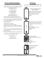
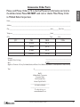
INDEX
Thank You ................................................................................................................................................................................ 2
9001z
Major 9001z Features ........................................................................................................................................................... 2
Installation ........................................................................................................................................................................... 2-3
CB Antenna ............................................................................................................................................................................. 3
9001z Features and Controls ............................................................................................................................................. 4
Feature Operation................................................................................................................................................................. 5
How to Operate Your CB ................................................................................................................................................... 6
Technical Specifications ........................................................................................................................................................ 7
Limited Warranty ................................................................................................................................................................... 7
Limitation of Liability ............................................................................................................................................................ 7
Service and Technical Support........................................................................................................................................8
Accessories ........................................................................................................................................................................8
Accessories Order Form ................................................................................................................................................9
Other Midland Products............................................................................................................................................... 10
www.midlandradio.com
1
Thank you
Installation
Congratulations on your purchase of a state-of-the-art
Midland 9001z mobile CB radio. In the years ahead, you can
expect to realize time and again why Midland holds the front
running position among CB users everywhere.You will come
to know that American Original is not just a slogan, but the
heading of long list of hearable, seeable benefits. As
your Midland CB experience unfolds and grows we hope you
will remember that CB radios are only one kind of electronic
excellence available under the Midland name.Your 40 channel
CB radio represents the state of the art in high tech engineering. The unit incorporates microprocessor
controlled PLL circuitry for precise tuning. The 9001z is a
classic style CB with the innovative Guardian alert feature
that is skillfully constructed with the finest components.This
radio is designed for reliable and trouble-free performance
for years to come. Enjoy!
Major 9001z Features
• 40 CB Channels
• 4 Watt Output Power
• Guardian Alert
• Weather Scan
• XTRA TALK Mic Control
• Instant Channel 9/19
• RF Gain
• Switchable Noise Blanker(NB)
• Delta Tune
• SWR Calibration
• XR Technology
• Automatic Noise Limiter(ANL)
• PA Function
• Last Channel Memory
• Push to talk ergonomically designed microphone
• 9 ft coil Mic cord
• Includes mounting bracket/hardware and fuse
DC power cord
Midland Radio Corporation
Hereby certifies that this unit has
been designed, manufactured,
FCC type accepted and certified
in accordance with part 95 and
Part 15, Subpart C of the current
FCC rules and regulations as of
the date of manufacture.
2
This transceiver may be installed in any 12-volt negative
ground-system car or truck. Most current U.S. and Foreign
vehicles use a negative system, but some older models
and some newer large trucks may have a positive ground.
Check the requirements for your vehicle before you begin
installation. Generally, you have a negative-ground system if
the minus (-) battery terminal is connected to the motor
block. Contact your dealer in the event you are unable to
determine your vehicle’s polarity system.
Location
Your new Midland CB is designed to be installed under the
dash or vertically on a console of your vehicle. Safety and
convenience are the primary considerations in deciding
exactly where to locate your radio.
Caution: Be sure that the unit is located so that it does
not interfere with the driver, supplemental restraint
systems (air bags), or impair access to any controls.
Connecting cables must be routed and secured in such a
manner as not to interfere with the operation of the brake,
accelerator or other controls. Interference from either
the unit or connecting cables may contribute to the loss of
control of the vehicle.
Mechanical Mounting
Step 1: Plug power cable into back of radio marked
“Power”. Be sure to observe polarity markings.
Step 2: Use the mounting bracket as a template for
marking the location of screw holes under the dash. Use
a nail or other sharp pointed object to mark the hole
locations.
Step 3: Drill a ‘1/8” hole for each screw hole in the
mounting bracket. Attach the bracket to the dash with the
Phillips head sheet metal screws provided.
NOTE: Extreme care should be exercised when
drilling into the dash to avoid damage to underdash electronic ignition, cruise control, instrument
and/ or accessory wiring.
Step 4: Attach removable 3-pin plug-in DC cord to polarized DC jack on the rear of the transceiver.
Step 5: Locate and secure the radio into the mounting
bracket, allowing working space for later power
connections.
www.midlandradio.com
Power Wiring (negative ground only)
Step 1: If you have not determined whether your vehicle has a
negative or positive ground, do so now. Then disconnect
the negative lead from the battery to prevent short
circuits that can occur during wiring. Do not connect this
transceiver to positive ground electrical systems.
Step 2: With negative ground:
A. Connect the positive (RED WIRE) the one with
in-line fuse holder to either the
( a ) fuse block
( b ) cigarette lighter or
( c ) directly to the positive post on your battery.
Usually, the fuse block is the most convenient connecting
point. It is also possible to connect to the accessory
terminal on the fuse block or ignition switch, so that your
CB automatically goes off when the ignition goes off.
B. Then tightly connect the ground (BLACK WIRE)
directly to the vehicle’s metal frame. A good direct
metal-to-metal ground is essential for optimum
performance.
Mounting the Main Unit
Step 1: Loosen the retaining knobs on each side of the
mounting bracket to give enough space for the unit to slide
between the two bracket arms.
Step 2: Position the main unit between the bracket arms in
line with the retaining knobs. Set the height and angle for
optimum operating comfort and accessibility.
Step 3: Tighten the retaining knobs.
Installation of Microphone Hanger
Mounting holes are provided on the microphone hanger bracket.
The bracket can be attached to the vehicle dash or other
convenient location.
CB Antenna
How to Select, Position, Install and Tune the Right
One for You
Basically, you may choose from two types of mobile CB
antennas - full-length whip and loaded whip - and a
variety of mounts (depending on where you locate your
antenna). Midland markets a line of high-performance
antennas.Visit our website at www.midlandradio. com
to check out the selection.
Where You Locate your Antenna Does Make a
Difference.
Some general rules for antenna location that can aid CB
performance:
1. Put your mount as high on the vehicle as possible.
The higher the proportion of antenna length that is
above the roof, the better.
2. If possible, mount the antenna in the center of whatever
surface you choose.
3. Keep antenna cables away from noise sources such as
the ignition system, gauges, etc.
4. Make sure you have a solid metal-to-metal ground.
5. Exercise care to prevent cable damage.
Essentially, you have five location choices: the roof, gutter,
rear deck, front cowl or rear bumper. Where you decide
to locate your antenna will determine the type of antenna
needed.
Antenna Installation:
Follow the manufacturer’s installation instructions carefully.
-Warning: Never operate your CB radio without
attaching an antenna or with a broken antenna cable. This
will result in damage to transmitter circuitry.
-Safety notice: The antenna used for this radio must be
installed to provide a separation distance of at least 34
cm (14 in.) from all persons and must not be collocated
or operating in conjunction with any other antenna or
transmitter.
Tuning your Antenna
Some antennas are factory tuned. However, performance
can usually be improved by slightly lengthening or shortening its length, using a Standing Wave Radio (SWR) meter.
For the exact procedures to be used refer to the antenna
manufacturer’s installation manual.
www.midlandradio.com
3
9001z
Installation Cont...
9001z Features and Controls
Front Panel Controls
Electret/Dynamic Mic S/RF/SWR/CAL
Selector Switch
Selector Switch
NB/ANL OFF CB/WX Scan/ PA
Selector Switch Selector Switch
CH9/ Norm/CH19
Selector Switch
Bright/Dim
Selector Switch
XR Technology
On/OFF Switch
Backlit S/RF/
SWR Meter
Channel LED
Readout
4-Pin Front Mic
Connector
Dual Knobs- ON/ Dual KnobsOFF/ Volume and XTRA Talk
Mic Gain and
Squelch
RF Gain
Delta Tune Knob SWR Calibration
Knob
Guardian Alert Channel Selector
Knob
Knob
Back Panel Controls
Antenna
Connector
4
www.midlandradio.com
PA Speaker
Jack
DC 13.8V
Power Jack
External
Speaker Jack
Midland Radio Corporation is not responsible for
personal injury, vehicle damage or death due to negligent
use of the 9001z.
9. Channel Selector Knob- This knob selects any one of the
40 Citizen Band channels. The selected channel is indicated by
the LED readout, directly above the Channel Selector Knob.
10. C-MIC/DYM Switch- Allows the user to switch the type
of microphone being used. It can be set to use an Electret
microphone (C-MIC) or a Dynamic Microphone (DYM).
11. S/RF/SWR/CAL Switch- This switch selects meter
function. S/RF is normal, SWR and CAL are for SWR
measurements only. See pg 6 for calibration instructions.
12. NB/ANL/OFF Switch- When this switch is in the NB
position, the RF Noise Blanker will be activated. The RF
Noise Blanker is very effective for cutting down on ignition
interference. When in the ANL position, the ANL is active to
reduce background noise.
13. CB/WX/PA Switch- This switch allows you to move from
CB mode to Weather (WX) scan mode and PA mode. When
the Weather scan is activated, the radio will begin scanning
and lock on the first weather channel broadcast signal
strong enough to use. If later the signal becomes too weak
to use the unit will automatically resume scanning to find a
usable signal. In PA mode, incoming CB transmissions will be
broadcast through the PA speaker. This allows you to hear
transmissions when you are not inside your vehicle. The PA
function should not be used unless a PA speaker is connected.
14. CH9/Nor/CH19 Switch- This switch is used for instant
selection of Emergency Channel 9, Informational Channel 19
or Normal CB operation.
15. BRT/DIM Switch- Used to adjust the brightness of the
LED.
16. XR Switch- This activates and deactivates the XR
technology, which is a noise filter than helps improve transmission range.
17.TX LED- Indicates when the radio is transmitting.
18. ANT LED- Indicates a high SWR condition with the
antenna system. Check antenna, cable and connections.
19. WX LED- Indicates when weather mode is activated.
www.midlandradio.com
5
9001z
Feature Operation
1. 4 Pin Microphone Connector
2. On/OFF Volume Knob- Turn clockwise to turn power on
and set to the desired listening volume.
3. Squelch Knob- This control is used to cut off or
eliminate receiver background noise in the absence of an
incoming signal. For maximum receiver sensitivity it is desired
that the control be adjusted only to the point where the
receiver background noise is eliminated. Adjust until the
receiver noise disappears. This will require the incoming signal
to be slightly stronger than the average receiver noise. Further clockwise rotation will increase the threshold level which
a signal must overcome in order to be heard. Only strong
signals will be heard at a maximum clockwise setting.
4. XTRA Talk Mic Gain Knob- Adjusts the microphone gain
in transmit and PA modes. This controls the gain to the extent
that full talk power is available several inches away from the
microphone. In the Public Address (PA) mode, the control
functions as the volume control.
5. RF Gain Knob-Adjust as required to optimize signal. This
control is used primarily to optimize reception in strong
signal areas. Gain is reduced by counter clockwise rotation
of the control.
6. Delta Tune Knob- Turn this fine tuning knob clockwise to
capture a more readable signal, as well as eliminate adjacent
channel interference.
7. SWR Knob (Standing Wave Ratio)-Allows for the
calibration of the meter for standing wave ratio measurements.
8. Guardian Alert Knob- This unique feature allows for the
setting of a timed alert that can be used for many different
things including keeping one alert while driving or setting an
appointment reminder. To activate, turn the knob clockwise
to choose a time increment- 1, 5, 10, 15, 20, 30, 40, 50, or 60
minutes. Once set, the radio will emit a loud beeping noise in
the specified increment. For example, if you set the alarm for
15 minutes, after 15 minutes the alarm will sound. To snooze
the alert for another 15 minutes, press the knob in once.
To deactivate, turn the knob to the OFF position. Warning:
The Guardian Alert is NOT intended as a substitute for
adequate rest. You should not operate a vehicle if you
are drowsy. During extended periods of vehicle operation,
you should take frequent breaks. NEVER OPERATE A
VEHICLE IF YOU ARE DROWSY.
How to Operate Your CB
1. Turn it on. Make sure the power cord, antenna and microphone are connected to their proper connectors before
starting.
2. Ensure the CB/PA switch is in the CB position.
3. Rotate the On/OFF volume knob clockwise to adjust the
volume to a normal listening level
4. Select one of the 40 channels using the channel selector knob
and adjust the volume. The selected channel will be indicated
on the LED.
5. Calibrate the SWR. This is critical in order to achieve
optimum performance. To do so, follow these steps:
A. Select channel 18.
B. Switch the S/RF/SWR/CAL to the CAL position.
C. Push and hold the PTT button on the microphone.
D. While holding the PTT button, adjust the SWR
Calibration knob so the meter needle swings to
the CAL (down arrow) mark on the right side of
the meter.
E. While holding down the PTT button, set the
S/RF/SWR/CAL switch to the SWR position to
read the SWR reading.
F. Repeat the same steps two through B-E on
channel 1 and 40 as well. This will check SWR for
all the channels.
Note: Calibration must be made in an open area (never in a
garage).Vehicle doors must be closed. No one should be standing
near the antenna.The reading will be slightly higher when
calibrating on channel 1 and 40 than on channel 18. Ideally
when switched to the SWR postion, the meter needle should be
as far left as possible. Anything over 3 is not acceptable.
8. To use an external speaker, connect an external speaker
to the external speaker jack on the rear panel. Ensure the
external speaker has 8-ohm impedance and is rated to handle
4.0 watts. When an external speaker is plugged in, the internal
speaker is automatically disabled.
9. To use Public Address mode, connect an external PA speaker
to the PA jack on the rear panel. Ensure the speaker has
8-ohm impedance and is rated to handle at least 4 watts.
Set the CB/PA switch to the PA position. Push and hold the
PTT button on the microphone and speak in a normal voice.
Your voice will transmit throught the PA speaker. Ensure the
speaker is directed away from the microphone to prevent
acoustic feedback.
6. To receive, ensure the radio is on and the CB/PA switch is
in the CB position and ensure the PTT on the microphone
is released. When receiving the Yellow LED will be lit. The
S-Meter will swing proportionately to the strength of the
incoming signal when receiving. In order to read the meter,
the S/RF/SWR/CAL switch must be in the S/RF position.
7. To transmit, ensure the radio is on and the CB/PA switch is
in the CB position. Adjust the XTRA Talk Mic Gain initially
all the way clockwise to ensure maximum voice volume is
available. Press the PTT on the microphone and hold the
microphone two inches from your mouth, speaking in a clear,
normal voice.
6
www.midlandradio.com
GENERAL
Frequency Range ................................................26.965-27.405 MHz
Frequency Control.............................................Phase Lock Loop (PLL)
Channels ...............................................................40
Modulation Type .................................................AM
Antenna Connector ..........................................SO-239
Antenna Impedance............................................50 Ohm
PA Speaker ...........................................................8-Ohm, 5 Watts
Microphone .........................................................1000 ohm Electret
Power Supply ......................................................13.8 VDC
Size ........................................................................10(D) x 2.25(H) x 7.25(W) in.
Unit Weight...........................................................3 lbs.
RECEIVER
Sensitivity...............................................................0.7 uV for 10dB s/n
Selectivity .............................................................45 dB + 10 kHz
Squelch Range .....................................................Adjustable less than 1 uV
Audio Output Power ........................................4 Watts
Distortion at 1000 mV .....................................3%
Audio Frequency Response ............................400-2400 Hz
Intermediate Frequency ...................................I° 10.695 MHz II° 455 kHz
Spurious Response ............................................more than 45 dB
TRANSMITTER
RF Output Power ..............................................4 Watts
Frequency Tolerance .........................................0.005%
Harmonic Suppression .....................................More than 60 dB
Modulation ..........................................................AM 90%( ± 5%)›
WEATHER RECEIVER
Channel
Frequency
Channel 1
162.400
Channel 2
162.425
Channel 3
162.450
Channel 4
162.475
Channel 5
162.500
Channel 6
162.525
Channel 7
162.550
Limited Warranty
Midland Radio Corporation will repair or
replace, at its option without charge, any Midland Citizen Band
transceiver which fails due to a defect in material or workmanship within Three Years following the initial consumer purchase.
This warranty does not apply to water damage, battery leak or
abuse. Accessories have a 90 day warranty from date of
purchase, including any antennas, chargers, or earphones. This
warranty does not include the cost of labor for removal or
re-installation of the product in a vehicle or other mounting.
For Product Purchased in the USA:
Performance of any obligation under this warranty may be
obtained by returning the warranted product, prepaid freight,
along with proof of purchase to:
Midland Radio Corporation
Warranty Service Department
5900 Parretta Drive
Kansas City, MO 64120
This warranty gives you specific legal rights, and you may also
have other rights, which vary from state to state. Note : The
above warranty applies only to merchandise purchased in the
United States of America or any of the territories or possessions thereof, or from a U.S. Military exchange.
For Product Purchased in Canada:
Performance of any obligation under this warranty may be
obtained by returning the warranted product, along with proof
of purchase to your dealer in Canada. This warranty gives you
specified legal rights. Additional warranty rights may be
provided by law in some areas.
Limitation of Liability
Sensitivity at 12dB S/N .....................................0.4 uV
Spurious Response ............................................more than 45dB
MIDLAND’S RESPONSIBILITY IN CONNECTION WITH THIS
PRODUCT IS LIMITED TO REPAIR OR REPLACEMENT OF THE
PRODUCT, OR REFUND OF ITS PURCHASE PRICE, AT THE SOLE
DISCRETION OF MIDLAND. MIDLAND DISCLAIMS ANY AND ALL
WARRANTIES, EXPRESS OR
IMPLIED, INCLUDING WARRANTIES OF MERCHANTABILITY AND
FITNESS FOR ANY PARTICULAR PURPOSE, AND NO OTHER
REMEDY SHALL BE AVAILABLE, INCLUDING, WITHOUT LIMITATION,
INCIDENTAL, SPECIAL, INDIRECT OR CONSEQUENTIAL
DAMAGES. IN NO EVENT SHALL MIDLAND’S LIABILITY EXCEED THE
PURCHASE PRICE OF THE PRODUCT AT ISSUE. SOME STATES DO
NOT PERMIT THE EXCLUSION OR LIMITATION OF INCIDENTAL
OR CONSEQUENTIAL DAMAGES AND, ACCORDINGLY,
THE ABOVE LIMITATIONS OR EXCLUSIONS MAY NOT APPLY TO
YOU.
www.midlandradio.com
7
9001z
Technical Specifications
Service and Technical Support
* If you have a problem which you believe requires service, please
call first and speak with a service technician. Many problems can be
remedied over the phone without returning the unit for service.
For Technical Support Contact:
Midland Radio Corporation
5900 Parretta Drive
Kansas City, Missouri 64120
Phone: (816) 241-8500
Fax: (816) 241-5713
E-mail: [email protected]
Website: www.midlandradio.com
If after talking with technical support you still feel your unit
needs to be returned for service, follow the below instructions:
1. Pack the unit in its original box and packing. Then pack the original
box in a suitable shipping carton. Caution: Improper packing may
result in damage during shipment.
2. Include the following:
a. full description of any problems
b. daytime telephone number, name & address
3. For warranty service include a photocopy of the bill of sale from
an authorized dealer or other proof of purchase showing the date
of sale.
4. You do not need to return accessory items (Fused DC power cord,
mounting hardware, Owners Guide) unless they might be directly
related to the problem.
5. A flat rate of $55.00 will apply to repairs not covered by warranty
or units that are over three years old. Send only cashier’s check,
money order or Master Card or Visa card number.
Send to:
Midland Radio Corporation
5900 Parretta Drive
Kansas City, Missouri 64120
Accessories
Accessories can be purchased at www.midlandradio.com or
fill in the form on the following page and mail it to our address.
18-2442
CENTER LOAD MAGNETIC MOUNT
MOBILE CB ANTENNA
• Center loaded with 17-7 stainless steel whip
• Relief spring for minimizing whip damage
• Plastic-coated base to prevent rust
• Prewired, includes cable, connector
• $17.99
18-258
WINDOW MOUNT 27 MHz CB ANTENNA
• Special process transfers energy from one
side of glass to the other without the need
of wires.
• Simple to install
• Rod is 17-7 stainless steel with new
BLACKKOTE finish
• $19.99
21-404C
CB EXTENSION SPEAKER
• 3” Dynamic speaker with switchable noise
filter
• 8-ohm
• Swivel base
• 5-foot cable with plug
• $19.99
S77038127
ACCESSORY CB MICROPHONE
• 6 ft Heavy Duty Cable
• 4-Pin Connection
• $15.00
8
www.midlandradio.com
9001z
Accessories Order Form
Please send Money Order or fill in the Visa/Mastercard information and mail to
the address below. Please DO NOT send cash or checks. Make Money Order
to Midland Radio Corporation.
Name:_________________________________________________________________________________________________
Address:_______________________________________________________________________________________________
City:__________________________________________________________________State:_________Zip Code:___________
Telephone:_____________________________________________________________Email:____________________________
CC#_________________________________________________________________ Type:_________Exp:_________________
QTY
ITEM
PRICE
18-2442
$17.99
18-258
$19.99
21-404C
$19.99
S77038127
$15.00
TOTAL
Sub-total
___________________ _____________________
Tax (MO, CO, IL, FL Only)
________________________________________
S&H
$14.95__________________________________
(Applies to Domestic US only. For Hawaii, Alaska, and Puerto Rico S&H will be $38.25 for 1 lb and $64.25 for 2lbs or more).
Total
$___________________________________________________________
Mail To:
Midland Radio Corporation
Consumer Dept.
5900 Parretta Drive
Kansas City, MO 64120
______________________________
Or Call 816.241.8500
______________________________
To order online go to
www.midlandradio.com
www.midlandradio.com
9
10
www.midlandradio.com
9001z
MIDLAND RADIO CORPORATION
5900 Parretta Drive
Kansas City, MO 64120
Call 816.241.8500
visit us at http://www.midlandradio.com
www.midlandradio.com
11