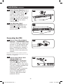
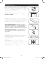
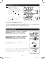
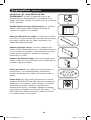
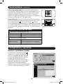
1
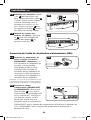
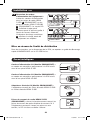
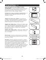
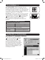
Re
to gis
R Wa
w ter e
r
ww in a on gis ra
w. FR line tr nt
tri EE t
y
o a
pp
lit Trip day tio
e. p fo
co L r n
m ite a
/w p ch
ar ro an
ra du c
nt c e
y t!
Owner’s Manual
PDUMH15NET/PDUMH20NET
Switched Rack PDU
• 120V, 50/60Hz AC Input and Output
Important Safety Instructions
2
Installation 3
Features5
Configuration and Operation
7
Technical Support
8
Warranty and Warranty Registration
8
Español9
Français17
1111 W. 35th Street, Chicago, IL 60609 USA
www.tripplite.com/support
Copyright © 2011 Tripp Lite. All rights reserved.
1
201110148-93-3042.indb 1
11/9/2011 11:21:04 AM
Important Safety Instructions
SAVE THESE INSTRUCTIONS
This manual contains instructions and warnings that should be
followed during the installation, operation, and storage of this
product. Failure to heed these instructions and warnings may
affect the product warranty.
• The PDU provides convenient multiple outlets, but it DOES NOT provide surge or
line noise protection for connected equipment.
• The PDU is designed for indoor use only in a controlled environment away from
excess moisture, temperature extremes, conductive contaminants, dust or direct
sunlight.
• Do not connect the PDU to an ungrounded outlet or to extension cords or adapters
that eliminate the connection to ground.
• The power requirement for each piece of equipment connected to the PDU must
not exceed the individual outlet’s load rating.
• The total power requirement for equipment connected to the PDU must not exceed
the maximum load rating for the PDU.
• Do not drill into or attempt to open any part of the PDU housing. There are no userserviceable parts inside.
• Do not attempt to modify the PDU, including the input plugs and power cables.
• Do not attempt to use the PDU if any part of it becomes damaged.
• Do not attempt to mount the PDU to an insecure or unstable surface.
• Never attempt to install electrical equipment during a thunderstorm.
• Use of this equipment in life support applications where failure of this equipment
can reasonably be expected to cause the failure of the life support equipment or to
significantly affect its safety or effectiveness is not recommended. Do not use this
equipment in the presence of a flammable anesthetic mixture with air, oxygen or
nitrous oxide.
2
201110148-93-3042.indb 2
11/9/2011 11:21:04 AM
Installation
Mounting the PDU
The PDU supports four primary mounting configurations: 1U Rack, 0U Rack (Vertical),
Wall and Under-Counter.
Note: Regardless of configuration, the user must determine the fitness of hardware and procedures before
mounting. The PDU and included hardware are designed for common rack and rack enclosure types and may
not be appropriate for all applications. Exact mounting configurations may vary. Screws for attaching the
mounting brackets and cord retention shelf to the PDU are included. Use only the screws supplied by the
manufacturer or their exact equivalent (#6-32, 3/16" flat head).
1-1 1U Rack Mounting: Use 3 screws
A to attach each of the 2 longer
mounting brackets B to the PDU
as shown. You can mount the PDU
in a recessed position by attaching
the mounting brackets so they
extend beyond the front panel of
the PDU. (If you plan to use the
cord retention shelf, attach the
mounting brackets in a recessed
position.) Mount the PDU in the
rack by inserting 4 user-supplied
screws C through the mounting
brackets B and into the mounting
holes of the rack rails.
1-1
A
B
C
1-2 0U Rack Mounting: Use 3 screws
A to attach each of the 2 shorter
mounting brackets B to the PDU
as shown. Mount the PDU
vertically by inserting 2 or more
user-supplied screws C through
the mounting brackets B and into
mounting points in the rack or
rack enclosure.
1-2
B
1-3 Wall Mounting: Use 3 screws A
to attach each of the 2 shorter
mounting brackets B to the PDU
as shown. Mount the PDU to the
wall by inserting 2 or more usersupplied screws C through the
mounting brackets B and into
secure mounting points.
A
C
A
C
1-3
B
3
201110148-93-3042.indb 3
11/9/2011 11:21:05 AM
Installation
continued
1-4 Under-Counter Mounting: Use 3
screws A to attach each of the 2
shorter mounting brackets B to
the PDU as shown. Mount the
PDU under the counter by
inserting 2 or more user-supplied
screws C through the mounting
brackets B and into secure
mounting points.
1-4
A
B
C
1-5 Cord Retention Shelf
Attachment (Optional): Use 2
screws A to attach the cord
retention shelf B to the front
panel of the PDU.
1-5
B
A
Connecting the PDU
2-1 Connect Input Plug Adapters
(Optional – PDUMH20NET Only):
The PDU includes an adapter that
converts its L5-20P locking input
plug to a standard 5-20P input
plug. Connecting this adapter is
optional. The PDU will function
normally without connecting this
adapter.
2-1
PDUMH20NET
Note: The AC power source should not share a
circuit with a heavy electrical load (such as an air
conditioner or refrigerator).
2-2 Connect Input Power Cord
(PDUMH15NET and
PDUMH20NET): Connect the
input plug A to a compatible
source of AC power, such as a
UPS system, PDU or utility outlet.
The PDU should be provided with
over-current protection:
PDUMH15NET with a maximum
15A branch-rated protection
device; PDUMH20NET with a
maximum 20A branch-rated
protection device.
2-2
A
4
201110148-93-3042.indb 4
11/9/2011 11:21:06 AM
Installation
continued
2-3 Equipment Power Cord
Connection: Insert power cords
into the NEMA 5-15R output
receptacles A (PDUMH15NET) or
NEMA 5-15/20R output
receptacles A (PDUMH20NET).
The LED B near each output
receptacle illuminates when the
receptacle is ready to distribute
live AC power. The digital load
meter C will display the total
connected equipment load in
amps.
2-3
A
PDUMH15NET
B
C
2-3
A
PDUMH20NET
B
C
Networking the PDU
For Instructions on networking the PDU, refer to the SNMPWEBCARD Quick Start
Guide on the included CD-ROM.
Features
AC Input Power Cord (Model PDUMH15NET): The cord
is permanently attached to the PDU and has a NEMA
5-15P plug.
AC Input Power Cord (Model PDUMH20NET): The cord
is permanently attached to the PDU and has a NEMA
L5-20P locking plug.
AC Input Adapter (Model PDUMH20NET): The adapter
converts a NEMA L5-20P input plug to a NEMA 5-20P
input plug.
NEMA 5-15R Output Receptacles (PDUMH15NET):
During normal operation, the output receptacles distribute
AC power to connected equipment. When an outlet is
live, its associated LED illuminates.
Features
5
201110148-93-3042.indb 5
11/9/2011 11:21:09 AM
Features
continued
NEMA 5-15/20R Output Receptacles (PDUMH20NET):
During normal operation, the output receptacles distribute
AC power to connected equipment. When an outlet is
live, its associated LED illuminates.
Digital Load Meter (Ammeter): The total electrical
current drawn by connected equipment is displayed on
the meter in amperes.
Cord Retention Shelf: When attached to the PDU, the
cord retention shelf provides secure attachment points for
the input cord and connected equipment cords. Use the
included cable ties to secure the cords to the shelf.
Longer Mounting Brackets: Use these brackets to
mount the PDU horizontally in a standard rack or rack
enclosure. The mounting depth can be adjusted by
attaching the brackets to different positions on the PDU.
Shorter Mounting Brackets: Use these brackets to
mount the PDU in a 0U rack, wall or under-counter
configuration.
Factory Port: The port is reserved for configuration by
factory authorized personnel only. Do not connect
anything to the port.
PS/2 Port: Use this port to connect a Tripp Lite
ENVIROSENSE environmental sensor to provide remote
temperature/humidity monitoring and a dry contact
interface to control and monitor alarm, security and
telecom devices. Contact Tripp Lite Customer Support at
(773) 869-1234 for ordering information. Note: Do not
connect a keyboard or mouse to this port.
6
201110148-93-3042.indb 6
11/9/2011 11:21:10 AM
Features
continued
Mini-DIN Serial Port: Use this port to provide a direct
terminal connection to a computer with a terminal
emulation program. A serial cable (part number 73-1025)
is included with the PDU. If you need to order a
replacement cable, contact Tripp Lite Customer Support
at (773) 869-1234.
Ethernet Port: Use this RJ-45 jack to connect the PDU
to the network with a standard Ethernet patch cable. The
Link LED A and Status LED B indicate several operating
conditions, as shown in the table below. This port is not
compatible with PoE (Power Over Ethernet) applications.
A
B
Network Operating Conditions
A Link LED Color
Off
No Network Connection
Flashing Amber
100 Mbps Network Connection
Flashing Green
10 Mbps Network Connection
B Status LED Color
Off
Card Not Initialized
Steady Green
Card Initialized and Operational
Flashing Amber
Error - Card Not Initialized
Configuration and Operation
Remote Monitoring and Control
The PDU provides remote monitoring A ,
outlet control B and more via Web
browser, telnet and SNMP-based
Network Management Systems. For
more information about configuration
and operation of the PDU via the
PowerAlert Web browser interface, refer
to the SNMPWEBCARD User's Guide,
included on the CD-ROM bundled with
the PDU.
A
B
7
201110148-93-3042.indb 7
11/9/2011 11:21:11 AM
Technical Support
Website: www.tripplite.com/support • E-mail: [email protected]
Warranty and Warranty Registration
LIMITED WARRANTY
Seller warrants this product, if used in accordance with all applicable instructions, to be free from original defects in material and
workmanship for a period of 2 years from the date of initial purchase. If the product should prove defective in material or
workmanship within that period, Seller will repair or replace the product, in its sole discretion. Service under this Warranty can only
be obtained by your delivering or shipping the product (with all shipping or delivery charges prepaid) to: Tripp Lite, 1111 W. 35th
Street, Chicago, IL 60609 USA. Seller will pay return shipping charges. Visit www.tripplite.com/support before sending any
equipment back for repair.
THIS WARRANTY DOES NOT APPLY TO NORMAL WEAR OR TO DAMAGE RESULTING FROM ACCIDENT, MISUSE, ABUSE OR NEGLECT.
SELLER MAKES NO EXPRESS WARRANTIES OTHER THAN THE WARRANTY EXPRESSLY SET FORTH HEREIN. EXCEPT TO THE EXTENT
PROHIBITED BY APPLICABLE LAW, ALL IMPLIED WARRANTIES, INCLUDING ALL WARRANTIES OF MERCHANTABILITY OR FITNESS,
ARE LIMITED IN DURATION TO THE WARRANTY PERIOD SET FORTH ABOVE; AND THIS WARRANTY EXPRESSLY EXCLUDES ALL
INCIDENTAL AND CONSEQUENTIAL DAMAGES. (Some states do not allow limitations on how long an implied warranty lasts, and
some states do not allow the exclusion or limitation of incidental or consequential damages, so the above limitations or exclusions
may not apply to you. This Warranty gives you specific legal rights, and you may have other rights which vary from jurisdiction to
jurisdiction).
WARNING: The individual user should take care to determine prior to use whether this device is suitable, adequate or safe for the
use intended. Since individual applications are subject to great variation, the manufacturer makes no representation or warranty
as to the suitability or fitness of these devices for any specific application.
WARRANTY REGISTRATION
Visit www.tripplite.com/warranty today to register the warranty for your new Tripp Lite product. You'll be automatically entered into
a drawing for a chance to win a FREE Tripp Lite product!*
* No purchase necessary. Void where prohibited. Some restrictions apply. See website for details.
FCC Notice, Class A
This device complies with part 15 of the FCC Rules. Operation is subject to the following two conditions: (1) This device may not
cause harmful interference, and (2) this device must accept any interference received, including interference that may cause
undesired operation.
Note: This equipment has been tested and found to comply with the limits for a Class A digital device, pursuant to part 15 of the
FCC Rules. These limits are designed to provide reasonable protection against harmful interference when the equipment is operated
in a commercial environment. This equipment generates, uses, and can radiate radio frequency energy and, if not installed and
used in accordance with the instruction manual, may cause harmful interference to radio communications. Operation of this
equipment in a residential area is likely to cause harmful interference in which case the user will be required to correct the
interference at his own expense. The user must use shielded cables and connectors with this equipment. Any changes or
modifications to this equipment not expressly approved by Tripp Lite could void the user’s authority to operate this equipment.
Regulatory Compliance Identification Numbers
For the purpose of regulatory compliance certifications and identification, your Tripp Lite product has been assigned a unique series
number. The series number can be found on the product nameplate label, along with all required approval markings and
information. When requesting compliance information for this product, always refer to the series number. The series number should
not be confused with the marking name or model number of the product.
WEEE Compliance Information for Tripp Lite Customers and Recyclers (European Union)
Under the Waste Electrical and Electronic Equipment (WEEE) Directive and implementing regulations, when customers buy new
electrical and electronic equipment from Tripp Lite they are entitled to:
•Send old equipment for recycling on a one-for-one, like-for-like basis (this varies depending on the country)
•Send the new equipment back for recycling when this ultimately becomes waste
Tripp Lite follows a policy of continuous improvement. Specifications are subject to change without notice.
1111 W. 35th Street, Chicago, IL 60609 USA
www.tripplite.com/support
8
201110148-93-3042.indb 8
201110148 • 93-3042EN
11/9/2011 11:21:11 AM
Manual del propietario
PDUMH15NET/PDUMH20NET
PDU con tomas de corriente controlables para bastidor
• 120V, 50/60Hz AC Input y Output
Instrucciones de seguridad importantes
10
Instalación
11
Características
13
Configuración y operación
15
Soporte técnico
16
Garantía
16
English1
Français17
1111 W. 35th Street, Chicago, IL 60609 USA
www.tripplite.com/support
© 2011 Tripp Lite. Todos los derechos reservados.
9
201110148-93-3042.indb 9
11/9/2011 11:21:11 AM
Instrucciones de seguridad importantes
GUARDE ESTAS INSTRUCCIONES
Este manual contiene instrucciones y advertencias que deben
seguirse durante la instalación, operación y almacenamiento de
este producto. De no seguirlas, se afectar la garantía del
producto.
• El PDU proporciona cómodas salidas múltiples, pero NO proporciona protección
contra sobretensión o ruido en la línea al equipo conectado.
• El PDU está diseñada sólo para empleo en interiores en un ambiente controlado,
lejos del exceso de humedad, temperaturas extremas, contaminantes conductores,
polvo o luz solar directa.
• No conecte el PDU a una salida sin conexión a tierra ni a cables de extensión o
adaptadores que eliminen la conexión a tierra.
• El requisito de potencia de cada equipo conectado a1 PDU no debe exceder la
capacidad de carga individual de la salida.
• El requisito de potencia total para el equipo conectado el PDU no debe exceder la
máxima capacidad de carga para el PDU.
• No taladre ni trate de abrir ninguna parte de la cubierta del PDU. No hay partes en
su interior que requieran mantenimiento por parte del usuario.
• No intente modificar el PDU, incluyendo los enchufes de entrada y los cables de
alimentación.
• No intente usar el PDU si alguno de sus componentes está dañado.
• No intente montar el PDU en una superficie insegura o inestable.
• Nunca intente instalar equipos eléctricos durante una tormenta eléctrica.
• El uso de este equipo en aplicaciones de soporte de vida en donde la falla de este
equipo pueda razonablemente hacer suponer que causará fallas en el equipo de
soporte de vida o afecte significativamente su seguridad o efectividad, no está
recomendado. No use este equipo en la presencia de una mezcla anestésica
inflamable con aire, oxigeno u óxido nitroso.
10
201110148-93-3042.indb 10
11/9/2011 11:21:11 AM
Instalación
Montaje del PDU
El PDU soporta cuatro configuraciones primarias de montaje: Bastidor 1U, Bastidor
0U (Vertical), En la pared, y debajo de la barandilla. Nota: Independientemente de la configuración, el usuario debe determinar la idoneidad de los materiales y
accesorios así como de los procedimientos antes del montaje. El PDU y el material incluido están diseñados
para racks (bastidores) y cajas de rack (bastidor) comunes, y pueden no ser apropiados para todas las
aplicaciones. Se incluyen los tornillos para fijar los soportes de montaje y la repisa para el retención de cables
al PDU. Use únicamente los tornillos suministrados por el fabricante o su equivalente exacto (#6-32, 3/16"
de cabeza plana).
1-1 Montaje en Bastidor 1U: Use 3
tornillos A para fijar cada uno de los
dos brazos de montajes más largos B
al PDU como se muestra. Puede montar
el PDU empotrado fijando los soportes
de montaje de tal forma que se extienda
más allá del panel frontal del PDU. (Si
desea usar la repisa de retención de
cables, fije los soportes de montaje en
posición empotrada.) Monte el PDU en
el bastidor insertando cuatro tornillos,
suministrados por el usuario, C a través
de los soportes de montaje D y los
hoyos de montaje en los rieles del
bastidor.
1-1
A
B
C
1-2 Montaje en Bastidor 0U
(Vertical): Use 3 tornillos A para
fijar cada uno de los 2 soportes
de montajes más largos B al PDU
como se muestra. Monte el PDU
verticalmente insertando 2 o más
tornillos, suministrados por el
usuario C a través de los soportes
de montaje D y los hoyos de
montaje en los rieles del bastidor
o el estante para bastidor.
1-2
B
1-3 Montaje en la pared: Use 3
tornillos A para fijar cada uno de
los 2 soportes de montaje más
cortos B al PDU como se
muestra. Monte el PDU a la pared
insertando 2 o más tornillos,
suministrados por el usuario C a
través de los soportes de montaje
D y en puntos de montajes
seguros.
A
C
A
C
1-3
B
11
201110148-93-3042.indb 11
11/9/2011 11:21:12 AM
Instalación
continuación
1-4 Montaje bajo el escritorio: Use
3 tornillos A para fijar cada uno
de los 2 soportes de montaje más
cortos B al PDU como se
muestra. Monte el PDU bajo el
escritorio insertando 2 o más
tornillos, suministrados por el
usuario C a través de los soportes
de montaje D y en puntos de
montajes seguros.
1-4
A
B
C
1-5 Colocación de la Repisa de
Control de Cables (Opcional):
Use 2 tornillos A para fijar la
repisa de control de cables B al
panel frontal del PDU.
1-5
B
A
Conexión del PDU
2-1
2-1 Conecte los adaptadores de
enchufe de entrada (Opcional—
únicamente PDUMH20NET): La
PDU incluye un adaptador que
convierte su enchufe de entrada
L5-20P con fijación a un enchufe
de entrada 5-20P estándar. La
conexión de este adaptador es
opcional. La PDU funcionará
normalmente sin conectar este
adaptador.
PDUMH20NET
Nota: la fuente de energía CA no deberá compartir
un circuito con una carga eléctrica pesada (como la
de una unidad de aire acondicionado o un
refrigerador).
2-2 Conecte el cable de
2-2
alimentación de energía de
entrada (PDUMH15NET y
A
PDUMH20NET): Conecte la
clavija de entrada A a una fuente
de energía de CA compatible, tal
como un sistema UPS, PDU o un
servicio público. Deberá
proporcionarse el PDU con protección de sobre corriente: PDUMH15NET con un
dispositivo de circuito ramificado de protección de máximo 15A, PDUMH20NET
con un dispositivo circuito ramificado de protección de máximo 20A.
12
201110148-93-3042.indb 12
11/9/2011 11:21:12 AM
Instalación
continuación
2-3 Conexión del Cable de
Alimentación del Equipo: Inserte
los cables de energía dentro de
los receptáculos de salida del
NEMA 5-15R A (PDUMH15NET)
o los receptáculos de salida del
NEMA 5-15/20R A
(PDUMH20NET). El LED B C
próximo a cada toma de corriente
se ilumina cuando la toma de
corriente está lista para distribuir
energía CA viva. El medidor digital
de carga C mostrará la carga
total del equipo conectado en
amperes.
2-3
A
PDUMH15NET
B
C
2-3
A
PDUMH20NET
B
C
Conectando Su PDU a la Red
Para más instrucciones acerca de cómo conectar la PDU en red, consulte la Guía de
inicio rápido SNMPWEBCARD en el CD-ROM que se incluye.
Características
Cable de alimentación de energía de CA (Modelo
PDUMH15NET): El cable está permanentemente
adherido al PDU y tiene una clavija NEMA 5-15P.
Cable de alimentación de energía de CA (Modelo
PDUMH20NET): El cable está permanentemente
adherido al PDU y tiene una clavija NEMA L5-20P.
El adaptador de entrada de CA (Modelo
PDUMH20NET): El adaptador convierte las clavijas de
entrada del NEMA L5-20P a clavijas de entrada NEMA
5-20P.
Receptáculos de salida NEMA 5-15R (PDUMH15NET):
Durante la operación normal, los receptáculos de salida
distribuyen la energía de CA al equipo conectado. Cuando
una salida está viva se ilumina el LED asociado.
13
201110148-93-3042.indb 13
11/9/2011 11:21:13 AM
Características continuación
Features continued
Receptáculos de salida NEMA 5-15/20R
(PDUMH20NET): Durante la operación normal, los
receptáculos de salida distribuyen la energía de CA al
equipo conectado. Cuando una salida está viva se ilumina
el LED asociado.
Medidor Digital de Carga (Amperímetro): La corriente
eléctrica total utilizada por el equipo conectado se
muestra en amperes en el medidor.
Repisa de Retención de cables: Cuando está instalada
en el PDU, la repisa de retención de cables brinda puntos
de sujeción seguros para los cables de entrada y los
cables del equipo conectado.
Soportes Montaje Largos: Use estos soportes para
montar el PDU horizontalmente en un bastidor estándar o
en un estante para bastidor. La profundidad del montaje
puede ajustarse fijando los soportes en diferentes
posiciones en el PDU.
Soportes de Montaje Cortos: Use estos soportes para
montar el PDU en una configuración para bastidor 0U, en
la pared o bajo el escritorio.
Puerto de fábrica: Este puerto está reservado para la
configuración, la cual deberá realizar solamente el
personal autorizado por la fábrica. No conecte nada al
puerto.
Puerto PS/2: Use este puerto para conectar el sensor
ambiental ENVIROSENSE de Tripp Lite para monitorear la
temperatura y humedad en forma remota y una interfaz
de contacto seco para controlar y monitorear los
dispositivos de alarma, seguridad y telecomunicaciones.
Comuníquese al Soporte a Clientes de Tripp Lite al (773)
869-1234 para solicitar información. Nota: No conecte
un teclado o ratón a este puerto.
14
201110148-93-3042.indb 14
11/9/2011 11:21:14 AM
Características
continuación
Puerto Serial Mini-DIN: Use este puerto para obtener
una conexión Terminal directa a una computadora con un
programa de emulación Terminal. Un cable serial (parte
número 73-1025) se incluye con el PDU. Si necesita
ordenar un cable de reemplazo comuníquese al Soporte a
Clientes de Tripp Lite al (773) 869-1234.
Puerto Ethernet: Use este enchufe RJ-45 para conectar
el PDU a la red con cable patch Ethernet estándar. El LED
de Encadenamiento A y el LED de Estatus B indican
varias condiciones de operación de acuerdo a lo mostrado
en la tabla abajo. Nota: Este puerto no es compatible con
la aplicación PoE (Power over Ethernet / Energía sobre la
Ethernet).
A
B
Condiciones de Operación de la Red
A Color del LED Acoplamiento [Link]
Apagado
Sin conexión a la red
Ambar Destellando
Conexión a la red a 100 Mbps
Verde Destellando
Conexión a la red a 10 Mbps
B Color del LED Estado [Status]
Apagado
Tarjeta no Inicializada
Verde Constante
Tarjeta Inicializada y en Operación
Ambar Destellando
Error - Tarjeta no Inicializada
Configuración y operación
Control y monitoreo remoto
El PDU ofrece monitoreo remoto A ,
control de las tomas de corriente B y
más vía navegador de Web, telnet y
Sistemas de Administración de Red
basados en SNMP. Para mayor
información acerca de configuración y
operación del PDU vía la interfaz de
navegador de Web de PowerAlert,
refiérase a la Guía del Usuario incluida
en el CD-ROM que acompaña al PDU.
A
B
15
201110148-93-3042.indb 15
11/9/2011 11:21:14 AM
Soporte técnico
Website: www.tripplite.com/support • Correo Electronico: [email protected]
Garantía
GARANTÍA LIMITADA
El vendedor garantiza que este producto, si se emplea de acuerdo con todas las instrucciones aplicables, no tendrá defectos en
materiales ni mano de obra por un período de 2 años a partir de la fecha de compra. Si se verifica que el producto tiene defectos
en los materiales o en la mano de obra dentro de dicho período, el vendedor reparará o reemplazará el producto, a su sola
discreción. Sólo puede obtenerse servicio bajo esta garantía, entregando o despachando el producto (con todos los cargos de
despacho o entrega pagados por adelantado) a: Tripp Lite, 1111 W. 35th Street, Chicago, IL 60609 USA. El vendedor pagará los
cargos de despacho del retorno. Visite www.tripplite.com/support antes de enviar algún equipo para reparación.
ESTA GARANTÍA NO SE APLICA AL DESGASTE NORMAL O A DAÑOS RESULTANTES DE UN ACCIDENTE, USO INADECUADO,
MALTRATO O NEGLIGENCIA. EL VENDEDOR NO EXPRESA NINGUNA OTRA GARANTÍA DISTINTA DE LA ESTABLECIDA EN ESTE
DOCUMENTO EN FORMA EXPLÍCITA. EXCEPTO HASTA EL GRADO PROHIBIDO POR LAS LEYES APLICABLES, TODAS LAS GARANTÍAS
IMPLÍCITAS, INCLUYENDO TODAS LAS GARANTÍAS DE COMERCIABILIDAD O IDONEIDAD, ESTÁN LIMITADAS EN DURACIÓN AL
PERÍODO DE GARANTÍA ESTABLECIDO ANTERIORMENTE; ESTA GARANTÍA EXCLUYE EXPRESAMENTE TODOS LOS DAÑOS
INCIDENTALES Y CONSECUENTES. (Algunos estados no permiten limitaciones sobre la duración de una garantía implícita, y algunos
estados no permiten la exclusión o limitación de daños incidentales o consecuentes, de modo que las limitaciones o exclusiones
mencionadas pueden no aplicarse a usted. Esta garantía le da derechos legales específicos, pero usted puede tener otros derechos
que varían de jurisdicción a jurisdicción.)
ADVERTENCIA: El usuario individual debe encargarse de determinar antes de usarlo, si este dispositivo es apropiado, adecuado o
seguro para el uso proyectado. Ya que las aplicaciones individuales están sujetas a gran variación, el fabricante no declara ni
garantiza la idoneidad o aptitud de estos dispositivos para ninguna aplicación específica.
Cumplimiento de las normas de los números de identificación
Para fines de identificación y certificación del cumplimiento de las normas, su producto Tripp Lite tiene asignado un número de
serie único. Puede encontrar el número de serie en la etiqueta de la placa de identificación del producto, junto con los símbolos
de aprobación e información requeridos. Al solicitar información sobre el cumplimiento de las normas para este producto, siempre
mencione el número de serie. El número de serie no debe ser confundido con el nombre de identificación ni con el número de
modelo del producto.
Información de sobre Cumplimiento de la WEEE para Clientes de Tripp Lite y Recicladores (Unión Europea)
Según la Directiva de Residuos de Aparatos Eléctricos y Electrónicos (Waste Electrical and Electronic Equipment, WEEE) y sus
reglamentos, cuando los clientes compran nuevos equipos eléctricos y electrónicos a Tripp Lite, tienen derecho a:
•Enviar equipos antiguos para reciclaje según una base de uno por uno, entre productos similares (esto varía dependiendo del
país)
•Enviar el equipo nuevo de vuelta para reciclaje cuando este se convierta finalmente en desecho
Tripp Lite tiene una política de mejoramiento continuo. Las especificaciones están sujetas a cambio sin previo aviso.
1111 W. 35th Street, Chicago, IL 60609 USA
www.tripplite.com/support
16
201110148-93-3042.indb 16
201110148 • 93-3042ES
11/9/2011 11:21:14 AM
Manuel du propriétaire
PDUMH15NET/PDUMH20NET
Unité de distribution d’alimentation (PDU) en bâti
• 120V, 50/60Hz AC Input et Output
Importantes consignes de sécurité
18
Installation 19
Caractéristiques
21
Configuration et fonctionnement
23
Assistance technique
24
Garantie
24
English1
Español9
1111 W. 35th Street, Chicago, IL 60609 USA
www.tripplite.com/support
Copyright 2011 Tripp Lite. Tous droits réservés.
17
201110148-93-3042.indb 17
11/9/2011 11:21:14 AM
Importantes consignes de sécurité
CONSERVER CES DIRECTIVES
Ce manuel contient des instructions et des mises en garde que
vous devez respecter durant l’installation, l’utilisation et
l’entreposage de ce produit. Le non-respect de ces instructions et
mises en garde affecter la garantie du produit.
• L’unité PDU offre de nombreuses prises pratiques mais elle N’offre PAS de
protection contre les surtensions transitoires et les parasites à l’équipement
connecté.
• L’unité PDU est conçue pour un usage en environnement contrôlé, à l’abri de
l’humidité excessive, des températures extrêmes, des contaminants conducteurs,
de la poussière ou de la lumière directe du soleil.
• Ne pas connecter l’unité PDU à une prise sans mise à la terre ou à des cordons
prolongateurs ou des adaptateurs qui éliminent la mise à la terre.
• La demande d'alimentation pour chaque pièce d'équipement connectée à l'unité
PDU ne doit pas dépasser la charge nominale d'une prise individuelle.
• La demande totale d'alimentation pour l'équipement connectée à l'unité PDU ne
doit pas dépasser la charge nominale maximale pour l'unité PDU.
• Ne jamais percer ou essayer d’ouvrir une quelconque partie du boîtier de l’unité
PDU. Aucune pièce interne ne peut être réparée par l’utilisateur.
• Ne pas essayer de modifier l’unité PDU, y compris les fiches d’entrée et les câbles
d’alimentation.
• Ne pas essayer d’utiliser l’unité PDU, si une de ses pièces est endommagée.
• Ne pas essayer de monter l’unité PDU sur une surface peu sûre ou instable.
• Ne jamais essayer de d’installer un équipement électrique pendant un orage.
• Il est déconseillé d'utiliser cet équipement dans des applications médicales où une
panne de cet équipement pourrait normalement provoquer la panne de
l'équipement de survie ou altérer notablement sa sécurité ou son efficacité. Ne pas
utiliser cet équipement en présence d'un mélange anesthétique inflammable avec
de l'air, de l'oxygène ou de l'oxyde nitreux.
18
201110148-93-3042.indb 18
11/9/2011 11:21:14 AM
Installation
Montage de l'unité de distribution d'alimentation (PDU)
L'unité peut être montée selon quatre configurations principales : bâti en 1U, bâti en
0U (vertical), au mur et à sous comptoir.
Nota : Sans tenir compte de la configuration, l'utilisateur doit déterminer la compatibilité de la quincaillerie et
les procédures avant d'effectuer l'installation. L'unité PDU et la quincaillerie incluse sont conçues pour des
types de bâti et boîtier courants et peuvent ne pas convenir à toutes les applications. Les vis pour fixer les
supports de fixation et la tablette de retenue des cordons à l'unité sont incluses. N'utilisez que les vis fournies
par le fabricant ou leur équivalent exact (#6-32 de 3/16 po, à tête plate).
1-1 Montage en bâti 1U : Utilisez 3
vis A pour fixer chacun des deux
supports de fixation longs B à l'unité,
comme illustré. Vous pouvez enfoncer
l'unité de distribution en fixant les
supports de fixation de manière à ce
qu'ils dépassent le panneau avant de
l'unité. (Si vous avez l'intention d'utiliser
la tablette de retenue des cordons, fixez
les supports de fixation en retrait.)
Montez l'unité de distribution dans le
bâti en insérant 4 vis (fournies par vous)
C dans les supports de fixation D et
dans les trous sur les rails du bâti.
1-1
A
B
C
1-2 Montage en bâti 0U (vertical) :
Utilisez 3 vis A pour fixer chacun
des deux supports de fixation
courts B à l'unité, comme illustré.
Montez l'unité de distribution
verticalement en insérant 2 vis (ou
plus, fournies par vous) C dans
les supports de fixation D et dans
les trous sur les rails du bâti ou
dans le coffret.
1-2
B
1-3 Montage mural : Utilisez 3 vis A
pour fixer chacun des deux
supports de fixation courts B à
l'unité, comme illustré. Montez
l'unité de distribution au mur en
insérant 2 vis (ou plus, fournies
par vous) C dans les supports de
fixation D et dans des points de
montage solides.
A
C
A
C
1-3
B
19
201110148-93-3042.indb 19
11/9/2011 11:21:15 AM
Installation
suite
1-4 Montage sous comptoir : Utilisez
3 vis A pour fixer chacun des
deux supports de fixation courts B
à l'unité, comme illustré. Montez
l'unité de distribution sous le
comptoir en insérant 2 vis (ou
plus, fournies par vous) C dans
les supports de fixation D et dans
des points de montage solides.
1-4
A
B
C
1-5 Tablette de retenue des
cordons (en option) : Utilisez 2
vis A pour fixer la tablette de
retenue des cordons B au
panneau avant de l'unité.
1-5
B
A
Connexion de l'unité de distribution d'alimentation (PDU)
2-1 Brancher les adaptateurs de
fiches d’entrée (en option—
PDUMH20NET seulement) : La
PDU comprend un adaptateur qui
convertit sa fiche d’entrée
verrouillable L5-20P en fiche
d’entrée 5-20P standard. La
connexion de cet adaptateur est
facultative. La PDU fonctionnera
normalement sans procéder à la
connexion de cet adaptateur.
2-1
PDUMH20NET
Remarque : La source de courant alternatif ne doit
pas partager de circuit avec une charge électrique
lourde (comme un climatiseur ou un réfrigérateur).
2-2 Brancher le cordon
d’alimentation (PDUMH15NET
2-2
et PDUMH20NET) : Brancher la
A
fiche d’entrée A à une source
d'alimentation CA compatible, telle
qu’un système ASC, une PDU ou
une prise de courant. La PDU
devrait être fournie avec une
protection contre les surintensités :
PDUMH15NET avec un appareil de sectionnement évalué pour la dérivation de
15 A, PDUMH20NET avec un appareil de sectionnement évalué pour la
dérivation de 20 A.
20
201110148-93-3042.indb 20
11/9/2011 11:21:16 AM
Installation
suite
2-3 Connexion du cordon
d’alimentation de l’équipement :
Insérer les cordons d’alimentation
dans les prises de sortie NEMA
5-15R A (PDUMH15NET) ou les
prises de sorties NEMA 5-15/20R
A (PDUMH20NET). Le voyant DEL
B à côté de chaque prise
s’allume quand la prise est prête à
fournir du courant alternatif.
L’indicateur de charge numérique
C affichera la charge totale de
l’équipement en ampères.
2-3
A
PDUMH15NET
B
C
2-3
A
PDUMH20NET
B
C
Mise en réseau de l’unité de distribution
Pour des instructions sur le réseautage de la PDU, se reporter au guide de démarrage
rapide SNMPWEBCARD sur le CD-ROM inclus. Caractéristiques
Cordon d’alimentation CA (Modèle PDUMH15NET) :
ce cordon est attaché en permanence à la PDU et est
muni d’une prise NEMA 5-15P.
Cordon d’alimentation CA (Modèle PDUMH20NET) :
ce cordon est attaché en permanence à la PDU et est
muni d’une prise NEMA L5-20P.
Adaptateur d’entrée CA (Modèle PDUMH20NET) :
l’adaptateur convertit les fiches d’entrée NEMA L5-20P en fiches d'entrée NEMA 5-20P.
Prises de courant de sortie NEMA 5-15R
(PDUMH15NET) : durant le fonctionnement normal, les
prises de courant de sortie distribue du courant CA à
l’équipement connecté. Lorsqu’une prise est sous
tension, la DEL lui étant associée s’allume.
21
201110148-93-3042.indb 21
11/9/2011 11:21:17 AM
Caractéristiques
Features continued
suite
Prises de courant de sortie NEMA 5-15/20R
(PDUMH20NET) : durant le fonctionnement normal, les
prises de courant de sortie distribue du courant CA à
l’équipement connecté. Lorsqu’une prise est sous
tension, la DEL lui étant associée s’allume.
Indicateur de charge numérique (ampèremètre) : La
totalité du courant électrique utilisé par l'unité sera
affichée en ampères.
Tablette de retenue des cordons : Quand elle est
installée à l'unité de distribution, la tablette de retenue
des cordons offre des points de fixation sûrs pour les
cordons d'entrée et de l'équipement connecté.
Supports de fixation longs : Utilisez ces supports pour
fixer l'unité de distribution horizontalement dans un bâti
ou un coffret standard. La profondeur de montage peut
être ajustée en fixant les supports dans différentes
positions sur l'unité.
Supports de fixation courts : Utilisez ces supports pour
fixer l'unité de distribution dans un bâti 0U, au mur ou
sous un comptoir.
Port d’usine : Ce port est réservé pour la configuration
en usine uniquement par du personnel autorisé. Ne rien
connecter à ce port.
Port PS/2 : Utiliser ce port pour connecter un capteur
environnemental ENVIROSENSE de Tripp Lite de façon à
fournir une surveillance à distance de la température et
de l'humidité et une interface à contact sec pour
commander et surveiller les dispositifs d'alarme, de
sécurité et de télécommunications. Appeler l'assistance à
la clientèle de Tripp Lite au (773) 869-1234 pour des
renseignements sur les commandes. Note : Ne pas
connecter de clavier ni de souris à ce port.
22
201110148-93-3042.indb 22
11/9/2011 11:21:17 AM
Caractéristiques
suite
Port série mini-DIN : Utiliser ce port pour faire une
connexion directe de terminal à un ordinateur avec un
programme d'émulation de terminal. Un câble série (pièce
no 73-1025) est joint à la PDU. Si vous avez besoin de
commander un câble de rechange, appeler le service à la
clientèle de Tripp Lite au (773) 869-1234
Port Ethernet : Utiliser cette prise RJ-45 pour connecter
la PDU au réseau à l'aide d'un cordon de raccordement
standard Ethernet. La DEL de lien A et la DEL de statut
B indiquent plusieurs conditions de fonctionnement,
comme le montre e tableau ci-dessous. Note :
Incompatible avec les applications PoE (Power Over
Ethernet).
A
B
Conditions de fonctionnement du réseau
A Couleur de la DEL
Arrêté
Ambre clignotant
Vert clignotant
de lien [Link]
Pas de connexion réseau
Connexion au réseau 100 Mbps
Connexion au réseau 10 Mbps
B Couleur de la DEL
Arrêté
Vert stable
Ambre clignotant
de statut [Status]
Carte non initialisée
Carte Initialisée et opérationnelle
Erreur- Carte non initialisée
Configuration et fonctionnement
Surveillance et commande à distance
La PDU offre la surveillance à distance
A , la commande de prises B et plus
via navigateur Web, telnet et les
systèmes de gestion de réseau SNMP.
Pour plus de renseignements au sujet
de la configuration et du fonctionnement
de la PDU via l'interface du navigateur
Web de PowerAlert, se reporter au mode
d'emploi de la SNMPWEBCARD, sur le
CD-ROM joint à la PDU.
A
B
23
201110148-93-3042.indb 23
11/9/2011 11:21:17 AM
Assistance technique
Website: www.tripplite.com/support • Courriel: [email protected]
Garantie
GARANTIE LIMITÉE
Le vendeur garantit que ce produit, s'il est utilisé selon toutes les directives applicables, est exempt de défauts d'origine de matériel
et de main-d'œuvre pour une période de 2 ans à partir de la date initiale d'achat. Si le produit s'avère défectueux en matériel ou
en main-d'œuvre durant cette période, le vendeur réparera ou remplacera le produit à sa discrétion. Vous pouvez obtenir un service
selon cette garantie seulement en livrant ou en expédiant le produit (avec les frais d'expédition et de livraison prépayés) à : Tripp
Lite, 1111 W. 35th Street, Chicago, IL 60609 USA. Le vendeur paierai les frais d'expédition de retour. Visitez www.tripplite.com/
support avant d'envoyer un équipement pour réparations.
CETTE GARANTIE NE S'APPLIQUE PAS À L'USURE NORMALE OU AUX DOMMAGES RÉSULTANT D'ACCIDENTS, DE MAUVAIS USAGE,
D'ABUS OU DE NÉGLIGENCE. LE VENDEUR N'OFFRE AUCUNE GARANTIE EXPLICITE AUTRE QUE LA GARANTIE EXPRESSÉMENT
SIGNIFIÉE À LA PRÉSENTE. EXCEPTÉ SELON LES LIMITES DE LA LOI APPLICABLE, TOUTES LES GARANTIES IMPLICITES, Y COMPRIS
TOUTES LES GARANTIES DE QUALITÉ MARCHANDE OU DE CONFORMITÉ À UN BESOIN PARTICULIER, SONT LIMITÉES EN DURÉE
À LA PÉRIODE DE GARANTIE ÉNONCÉE CI DESSUS ET CETTE GARANTIE EXCLUE EXPLICITEMENT TOURS LES DOMMAGES
ACCESSOIRES OU CONSÉCUTIFS. Certains états ne permettent pas la limitation de la durée d'une garantie implicite et certains
états ne permettent pas la limitation ou l'exclusion de dommages accessoires ou consécutifs, en conséquence, les limitations et
les exclusions ci dessus pourraient ne pas s'appliquer à vous. Cette garantie vous donne des droits légaux spécifiques et vous
pourriez avoir d'autres droits selon les juridictions.
MISE EN GARDE : L'utilisateur devra prendre soin de déterminer avant de l'utiliser si cet appareil convient, est adéquat et sûr pour
l'usage prévu. Puisque les applications individuelles sont sujettes à de grandes variations, le fabricant ne fait aucune représentation
ni n'offre de garantie quand à l'applicabilité et à la conformité de ces appareils pour une application particulière.
Numéros d’identification de conformité aux règlements
À des fins de certification et d’identification de conformité aux règlements, votre produit Tripp Lite a reçu un numéro de série unique. Ce numéro se retrouve sur la plaque signalétique du produit, avec les inscriptions et informations d’approbation requises. Lors
d’une demande d’information de conformité pour ce produit, utilisez toujours le numéro de série. Il ne doit pas être confondu avec
le nom de la marque ou le numéro de modèle du produit.
L’information de conformité WEEE pour les clients de Tripp Lite et recycleurs (Union européenne)
Sous les directives et règlements de déchet d’équipements électrique et électronique (Waste Electrical and Electronic Equipment,
WEEE), lorsque les clients achètent le matériel électrique et électronique neuf de Tripp Lite ils sont autorisés à :
•Envoyer le vieux matériel pour le recyclage sur une base de un-contre-un et en nature (ceci varie selon le pays)
•Renvoyer le matériel neuf pour recyclage quand ceci devient éventuellement un rebut
La politique de Tripp Lite est celle d'une amélioration continuelle. Les spécifications peuvent être modifiées sans préavis.
1111 W. 35th Street, Chicago, IL 60609 USA
www.tripplite.com/support
24
201110148-93-3042.indb 24
201110148 • 93-3042FR
11/9/2011 11:21:18 AM