1
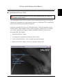
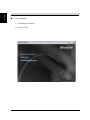
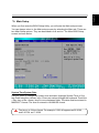
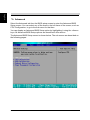
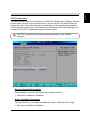
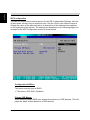
Shuttle Xvision User Guide For the : X50V2 Series TABLE OF CONTENTS Driver and Software Installation...................................................................................1 Mainboard Driver DVD ............................................................................................1 User Manuals ..................................................................................................2 Appendix......................................................................................................................3 Starting BIOS...........................................................................................................3 Enter the BIOS.........................................................................................................3 Main Setup ......................................................................................................5 Advanced ........................................................................................................6 CPU Configuration..................................................................................7 IDE Configuration....................................................................................8 USB Configuration................................................................................12 Onboard Device Configuration..............................................................14 Power Management Configuration........................................................16 Boot .............................................................................................................. 17 Boot Settings Configuration..................................................................18 Boot Device Priority...............................................................................19 Hard Disk Drives...................................................................................20 Security ........................................................................................................ 21 Exit ................................................................................................................23 Shuttle® Shuttle Xvision Installation Guide Copyright ©2011 by Shuttle® Inc. All Rights Reserved. No part of this publication may be reproduced, transcribed, stored in a retrieval system, translated into any language, or transmitted in any form or by any means such as electronic, mechanical, magnetic, optical, chemical, photocopy, manual, or otherwise, without prior written permission from Shuttle® Inc. Other brands and product names used herein are for identification purposes only and may be trademarks of their respective owners. Disclaimer Shuttle® Inc. shall not be liable for any incidental or consequential damages resulting from the performance or use of this product. Shuttle® Inc. makes no representation or warranty regarding the contents of this manual. Information in this manual had been carefully checked for accuracy;however, no guarantee is given as to the correctness of the contents. For continuing product improvement, Shuttle® Inc. reserves the right to revise the manual or make changes to the specifications of this product at any time without notice and obligation to any person or entity regarding such change. The information contained in this manual is provided for general use by customers. This device complies to Part 15 of the FCC Rules. Operation is subject to the following two conditions: 1.This device may not cause harmful interference. 2.This device must withstand any background interference including those that may cause undesired operation. Trademarks Shuttle is a registered trademark of Shuttle Inc. Intel and Pentium are registered trademarks of Intel Corporation. PS/2 is a registered trademark of IBM Corporation. AWARD is a registered trademark of Award Software Inc. Microsoft and Windows are registered trademarks of Microsoft Corporation. General Notice Other brand and product names used herein are for identification purposes only and may be trademarks of their respective owners. Safety Information Read the following precautions before setting up a Shuttle Xvision. CAUTION Incorrectly replacing the battery may damage this computer. Replace only with the same or equivalent as recommended by Shuttle. Dispose of used batteries according to the manufacturer's instructions. Using electrical power • This product should be operated from the type of power indicated on the marking label. If you are not sure of the type of power available, consult your dealer or local power company. • Do not allow anything to rest on the power cord. Do not locate this product where people will walk on the cord. • If an extension cord is used with this product, make sure that the total ampere rat ing of the equipment plugged into the extension cord does not exceed the exten sion cord ampere rating . Also, make sure that the total rating of all products plugged into the wall outlet does not exceed the fuse rating. • Do not overload a power outlet, strip or receptacle by plugging in too many devic es. The overall system load must not exceed 80% of the branch circuit rating. If power strips are used, the load should not exceed 80% of the power strip's inpu rating. • This product's AC adapter is equipped with a three-wire grounded plug. The plug only fits in a grounded power outlet. Make sure the power outlet is properly grounded before inserting the AC adapter plug. Do not insert the plug into a non- grounded power outlet. Contact your electrician for details. The unit can be operated at an ambient temperature of max. 35OC(95OF). Do not O O subject it to temperatures below 0 C(32 F)or above 35 OC(95OF). CAUTION: MODEL S167X2 IS DESIGNED TO USE WITH THE FLLOWING AC ADAPTER MODEL ONLY Manufacture: FSP Model: FSP040-RAC Manufacture: Lite-On Model: PA-1400-11 Warning! The grounding pin is a safety feature. Using a power outlet that is not properly grounded may result in electric shock and/or injury. Note: The grounding pin also provides good protection from unexpected noise or produced by other nearby electrical devices that may interfere with the performance of this product. Using electrical power • Use the product only with the supplied power supply cord set. If you need to replace the power cord set, make sure that the new power cord meets the follow ing requirements: detachable type, UL listed/CSA certified, type SPT-2, rated 7 A 125 V minimum, VDE approved or its equivalent, 4.6 meters (15 feet) maximum length. • Do not use inferior extension cords as this may result in damage to your notebook. The notebook comes with its own AC adapter. Do not use a different adapter to power the computer and other electrical devices. CAUTION for plug as disconnecting device Observe the following guidelines when connecting and disconnecting power to the power supply unit: • Install the power supply unit before connecting the power cord to the AC power outlet. • Unplug the power cord before removing the power supply unit from the computer. • If the system has multiple sources of power, disconnect power from the system by un plugging all power cords from the power supplies. CAUTION for Accessibility • Be sure that the power outlet you plug the power cord into is easily accessible and locat ed as close to the equipment operator as possible. When you need to disconnect power to the equipment, be sure to un plug the power cord from the electrical outlet. LCD display resolution • The LCD display, with an optimal resolution of 1366 x 768. English Driver and Software Installation Motherboard Driver DVD The DVD contents attached in X50V2 Series motherboard are subject to change without notice. The Motherboard Driver DVD contains all the motherboard drivers necessary to optimize the performance of this Shuttle Xvision in a Windows® OS. Install these drivers after installing Microsoft® Windows®. Insert the attached DVD into your DVD-ROM drive. The DVD AutoRun screen should appear. If the AutoRun screen does not appear, double click on Autorun icon in My Computer to bring up Shuttle Mainboard Software Setup screen. Navigation Bar Description : Auto Install Driver/ Utility. User Manuals - Motherboard Manual, Quick Guide. Link to Shuttle Website - Link to shuttle website homepage. Browse this DVD - Allows you to see contents of this DVD. English User Manuals Motherboard Manual Quick Guide English Appendix Starting BIOS AMIBIOS has been integrated into many motherboards for over a decade. In the past, people often referred to the AMIBIOS setup menu as BIOS, BIOS setup, or CMOS setup. American Megatrends refers to this setup as BIOS. Specifically, it is the name of the AMIBIOS8 BIOS setup utility. This chapter describes the basic navigation of the BIOS setup screens. Enter the BIOS To enter the BIOS setup screens, follow the steps below: Step1. Power on the motherboard. Step2. Press the <Delete> key on your keyboard when you see the following text prompt: Press DEL to run Setup. Step3. After you press the <Delete> key, the main BIOS setup menu displays. You can access the other setup screens from the main BIOS setup menu, such as the Chipset and Power menus. This manual describes the standard look of the BIOS setup screen. The motherboard manufacturer has the ability to change any and all of the settings described in this manual. This means that some of the options described in this manual do not exist in your motherboard's AMIBIOS. In most cases, the <Delete> key is used to invoke the BIOS setup screen. There are a few cases that other keys are used, such as <F1>,<F2>, and so on. BIOS Setup Menu The main BIOS setup menu is the first screen that you can navigate. Each main BIOS setup menu option is described in this user’s guide. The Main BIOS setup menu screen has two main frames. The left frame displays all the options that can be configured. “Grayed-out” options cannot be configured. Options is blue can be. The right frame displays the key legend. Above the key legend is an area reserved for a text message. When an option is selected in the left frame, it is highlighted in white. Often a text message will accompany it. English AMIBIOS8 has default text messages built into it. The motherboard manufacture retains the option to include, leave out, or change any of these text messages. They can also add their own text messages. Because of this, many screen shots in this manual are different from your BIOS setup screen. The BIOS setup/utility uses a key-based navigation system called hot keys. Most of the BIOS setup utility hot keys can be used at any time during the setup navigation process. These keys include <F1>, <F10>, <Enter>, <ESC>, <Arrow> keys, and so on. There is a hot key legend located in the right frame on most BIOS setup screens. Hot Key Description → Left ← Right The Left and Right <Arrow> keys allow you to select a BIOS setup screen. For example: Main screen, Advanced screen, Chipset screen, and so on. ↑ Up ↓ Down The Up and Down <Arrow> keys allow you to select an BIOS setup item or subscreen. +- Plus/Minus The Plus and Minus <Arrow> keys allow you to change the field value of a particular setup item. For example: Date and Time. Tab The <Tab> key allows you to select BIOS setup fields. F1 The <F1> key allows you to display the General Help screen. Press the <F1> key to open the General Help screen. F10 The <F10> key allows you to save any changes you have made and exit BIOS Setup. Press the <F10> key to save your changes. Press the <Enter> key to save the configuration and exit. You can also use the <Arrow> key to select Cancel and then press the <Enter> key to abort this function and return to the previous screen. ESC The <Esc> key allows you to discard any changes you have made and exit the BIOS Setup. Press the <Esc> key to exit the BIOS setup without saving your changes. Press the <Enter> key to discard changes and exit. You can also use the <Arrow> key to select Cancel and then press the <Enter> key to abort this function and return to the previous screen. Enter The <Enter> key allows you to display or change the setup option listed for a particular setup item. The <Enter> key can also allow you to display the setup subscreens. The <F8> key on your keyboard is the Fail-Safe key. It is not displayed on the BIOS key legend by default. To set the Fail-Safe settings of the BIOS, press the <F8> key on your keyboard. It is located on the upper row of a standard 101 keyboard. The Fail-Safe settings allow the motherboard to boot up with the least amount of options set. This can lessen the probability of conflicting settings. English Main Setup When you first enter the BIOS Setup Utility, you will enter the Main setup screen. You can always return to the Main setup screen by selecting the Main tab. There are two Main Setup options. They are described in this section. The Main BIOS Setup screen is shown below. System Time/System Date Use this option to change the system time and date. Highlight System Time or System Date using the <Arrow> keys. Enter new values through the keyboard. Press the <Tab> key or the <Arrow> keys to move between fields. The date must be entered in MM/DD/YY format. The time is entered in HH:MM:SS format. The time is in 24-hour format. For example, 5:30 A.M. appears as 05:30:00, and 5:30 P.M. as 17:30:00. English Advanced Select the Advanced tab from the BIOS setup screen to enter the Advanced BIOS Setup screen. You can select any of the items in the left frame of the screen, such as CPU Configuration, to go to the sub menu for that item. You can display an Advanced BIOS Setup option by highlighting it using the <Arrow> keys. All Advanced BIOS Setup options are described in this section. The Advanced BIOS Setup screen is shown below. The sub menus are described on the following pages. English CPU Configuration You can use this screen to select options for the CPU Configuration Settings. Use the up and down <Arrow> keys to select an item. Use the <Plus> and <Minus> keys to change the value of the selected option. A description of the selected item appears on the right side of the screen. The settings are described on the following pages. An example of the CPU Configuration screen is shown below. The CPU Configuration setup screen varies depending on the installed processor. Execute-Disable Bit Capability When disabled, force the XD feature flag to always return 0. The choice: Enabled or Disabled. Hyper Threading Technology This item allows you to enable or disable the Hyper Threading Technology. The choice: Enabled or Disabled. English IDE Configuration You can use this screen to select options for the IDE Configuration Settings. Use the up and down <Arrow> keys to select an item. Use the <Plus> and <Minus> keys to change the value of the selected option. A description of the selected item appears on the right side of the screen. The settings are described on the following pages. An example of the IDE Configuration screen is shown below. Configuration SATA as This option sets the type of SATA. The choice: IDE, AHCI, Disabled. Primary IDE Master While entering setup, BIOS auto detects the presonce of IDE devices. This displays the status of auto detection of IDE devices. Press <Enter> to access the sub menu for the IDE drives. The screen is shown below. Type This option sets the type of device that the AMIBIOS attempts to boot from after the Power-On Self-Test (POST) has completed. The choice: Not Installed,Auto,CD/DVD,ARMD. LBA/Large Mode LBA (Logical Block Addressing) is a method of addressing data on a disk drive. In LBA mode, the maximum drive capacity is 137 GB. The choice: Disabled,Auto. For drive capacities over 137 GB, your AMIBIOS must be equipped with 48-bit LBA mode addressing. If not, contact your motherboard manufacturer or install an ATA/133 IDE controller card that supports 48-bit LBA mode. English ******************************************************************************************* English Block (Multi-Sector Transfer) This option sets the block mode multi sector transfers option. The Optimal and Fail-Safe default setting is Auto. The choice: Disabled,Auto. PIO Mode IDE PIO (Programmable I/O) mode programs timing cycles between the IDE drive and the programmable IDE controller. As the PIO mode increases, the cycle time decreases. The choice: Auto,0,1,2,3,4. DMA Mode This setting allows you to adjust the DMA mode options. The choice:Auto,SWDMAn, MWDMAn, UDMAn. S.M.A.R.T. for Hard disk drives Self-Monitoring Analysis and Reporting Technology (SMART) feature can help predict impending drive failures. The choice: Auto,Enabled,Disabled. 32Bit Data Transfer This option sets the 32-bit data transfer option. The choice: Enabled, Disabled. **************************************************************************************** 10 English Hard Disk Write Protect Set this option to protect the hard disk drive from being overwritten. The Optimal and Fail-Safe default setting is Disabled. Disabled:Set this value to allow the hard disk drive to be used normally. Read, write, and erase functions can be performed to the hard disk drive. This is the default setting. Enabled:Set this value to prevent the hard disk drive from being erased. The choice: Enabled, Disabled. IDE Detect Time Out (Sec) Set this option to stop the AMIBIOS from searching for IDE devices within the specified number of seconds. Basically, this allows you to fine-tune the settings to allow for faster boot times. Adjust this setting until a suitable timing that can detect all IDE disk drives attached is found. The Optimal and Fail-Safe default setting is 35. The choice: 0, 5, 10, 15, 20, 25, 30, 35. Different IDE disk drives take longer for the BIOS to locate than others do. 11 English USB Configuration You can use this screen to select options for the USB Configuration. Use the up and down <Arrow> keys to select an item. Use the <Plus> and <Minus> keys to change the value of the selected option. The settings are described on the following pages. The screen is shown below. USB Function Set this value to allow the system to enable or disable the onboard USB ports. The Optimal and Fail-Safe default setting is Enabled. Disabled:This setting makes the onboard USB ports unavailable. Enabled:This setting allows the use of the USB ports. This is the default setting. The choice: Enabled, Disabled. USB 2.0 Controller Mode This item allows you to enable or disable the USB 2.0 Controller. The choice: Enabled or Disabled. 12 English USB 2.0 Controller Mode Configures the USB 2.0 Controller in HiSpeed(480 Mbps) or FullSpeed(12Mbps). The choice: HiSpeed or FullSpeed. Legacy USB Support Legacy USB Support refers to the USB mouse and USB keyboard support. Normally if this option is not enabled, any attached USB mouse or USB keyboard will not become available until a USB compatible operating system is fully booted with all USB drivers loaded. When this option is enabled, any attached USB mouse or USB keyboard can control the system even when there is no USB drivers loaded on the system. Set this value to enable or disable the Legacy USB Support. The Optimal and Fail-Safe default setting is Disabled. Disabled: Set this value to prevent the use of any USB device in DOS or during system boot. This is the default setting. Enabled: Set this value to allow the use of USB devices during boot and while using DOS. Auto: This option auto detects USB Keyboards or Mice and if found, allows them to be utilized during boot and while using DOS. The choice: Disabled or Enabled . 13 English Onboard Device Configuration You can use this screen to select options for the Onboard Device Configuration. Use the up and down <Arrow> keys to select an item. Use the <Plus> and <Minus> keys to change the value of the selected option. The settings are described on the following pages. The screen is shown below. LAN Remote Boot Decide whether to invoke the boot ROM of the onboard LAN chip. The choice: Enabled, Disabled. High Definition Audio This item allows you to enable or disable the High Definition Audio. The choice: Enabled, Disabled. Internal Graphics Mode Select This item allows you to set the Internal Graphics Mode. The choice: Enabled 8MB. 14 English Boot Display Device This item allows you to set the Boot Display Device. The choice: D-Sub Only, LVDS, D-Sub + LVDS. DVMT Mode Select This item allows you to set the DVMT Mode. The choice: Fixed Mode, DVMT Mode. DVMT/FIXED Memory This item allows you to set the DVMT/FIXED Memory. The choice: 128MB, 256MB, Maximum DVMT. 15 English Power Management Configuration You can use this screen to select options for the Power Management Configuration. Use the up and down <Arrow> keys to select an item. Use the <Plus> and <Minus> keys to change the value of the selected option. The settings are described on the following pages. The screen is shown below. Suspend mode Select the ACPI state used for System Suspend. The choice: S1(POS), S3(STR). Repost Video on S3 Resume Determines whether to invoke VGA BIOS POST on S3/STR resume. The choice: Yes, No. ACPI Version Features This item allows you to select the ACPI Version. The choice: ACPI v1.0, ACPI v2.0, ACPI v3.0 . 16 English Onboard LAN Wakeup From S4/S5 This item allows you to enable/disable the Onboard LAN Wakeup function from S4/S5 mode. The choice: Enabled, Disabled. Boot Select the Boot tab from the BIOS setup screen to enter the Boot BIOS Setup screen. You can select any of the items in the left frame of the screen, such as Boot Settings Configuration, to go to the sub menu for that item. You can display an Boot BIOS Setup option by highlighting it using the <Arrow> keys. All Boot BIOS Setup options are described in this section. The Boot BIOS Setup screen is shown below. The sub menus are described on the following pages. 17 English Boot Settings Configuration You can use this screen to select options for the Boot Settings Configuration. Use the up and down <Arrow> keys to select an item. Use the <Plus> and <Minus> keys to change the value of the selected option. The settings are described on the following pages. The screen is shown below. Boottup Nnum-Lock Select Power-on state for Nnumlock. The choice: ON or OFF. Wait For 'F1' If Error This item allows you to enable or disable the Wait For 'F1' If Error. The choice: Enabled, Disabled. Hit 'DEL' Message Display This item allows you to enable or disable the Hit 'DEL' Message Display. The choice: Enabled, Disabled. 18 English Boot Device Priority This item allows you to select Boot Devices Priority. When you select a boot category from the boot menu, a list of devices in that category appears. For example, if the system has three hard disk drives connected, then the list will show all three hard disk drives attached. 19 English Hard Disk Drives This item allows you to select Hard Disk Book Device Priority. 20 English Security Select the Security tab from the BIOS setup screen to enter the Security BIOS Setup screen. You can display an Security BIOS Setup option by highlighting it using the <Arrow> keys. All Security BIOS Setup options are described in this section. The Security Setup screen is shown below. The sub menus are documented on the following pages. Supervisor Password Indicates whether a supervisor password has been set. If the password has been installed, Installed displays. If not, Not Installed displays. User Password Indicates whether a user password has been set. If the password has been installed, Installed displays. If not, Not Installed displays. Change Supervisor Password Select Change Supervisor Password from the Security Setup menu and press <Enter>. Enter New Password: 21 English appears. Type the password and press <Enter>. The screen does not display the characters entered. Retype the password as prompted and press <Enter>. If the password confirmation is incorrect, an error message appears. The password is stored in NVRAM after BIOS completes. Change User Password Select Change User Password from the Security Setup menu and press <Enter>. Enter New Password: appears. Type the password and press <Enter>. The screen does not display the characters entered. Retype the password as prompted and press <Enter>. If the password confirmation is incorrect, an error message appears. The password is stored in NVRAM after BIOS completes. Boot Sector Virus Protection This option is near the bottom of the Security Setup screen. The Optimal and Fail-Safe default setting is Disabled. [Disabled]Set this value to prevent the Boot Sector Virus Protection. This is the default setting. [Enabled] Select Enabled to enable boot sector protection. Bios displays a warning when any program (or virus) issues a Disk Format command or attempts to write to the boot sector of the hard disk drive. If enabled, the following appears when a write is attempted to the boot sector. You may have to type N several times to prevent the boot sector write. 22 Boot Sector Write! Possible VIRUS: Continue (Y/N)? _ Format!!! Possible VIRUS: Continue (Y/N)? _ The choice: Enabled or Disabled. Bios Write Protect Choose [Enabled] to avoid virus destroy BIOS. If you want to flash BIOS, you must set it [Disabled]. The choice: Enabled or Disabled. Exit Select the Exit tab from the BIOS setup screen to enter the Exit BIOS Setup screen. You can display an Exit BIOS Setup option by highlighting it using the <Arrow> keys. All Exit BIOS Setup options are described in this section. The Exit BIOS Setup screen is shown below. 23 English The following appears after any attempt to format any cylinder, head, or sector of any hard disk drive via the BIOS INT 13 Hard disk drive Service: English Save Changes and Exit When you have completed the system configuration changes, select this option to leave BIOS Setup and reboot the computer so the new system configuration parameters can take effect. Select "Save Changes and Exit" from the Exit menu and press <Enter>. Save Configuration Changes and Exit Now? [Ok] [Cancel] appears in the window. Select Ok to save changes and exit. Exit without Saving Changes Select "Exit without Saving Changes" from the Exit menu and press <Enter>. Select Ok to discard changes and Exit. Load Optimal Defaults BIOS automatically sets all BIOS Setup options to a complete set of default settings when you Select this option. The Optimal settings are designed for maximum system performance, but may not work best for all computer applications. In particular, do not use the Optimal BIOS Setup options if your computer is experiencing system configuration problems. Select Load Optimal Defaults from the Exit menu and press <Enter>. Select Ok to load optimal defaults. 24