Transcript
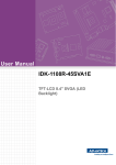
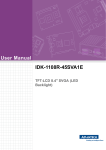
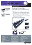
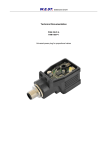
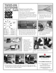
WALL
MOUNT
PATCH PANEL
QUICK
START
GUIDE
Thank you for purchasing this INTELLINET NETWORK SOLUTIONS™ Wall Mount
Patch Panel.
Follow the steps on this quick start guide for easy installation and use of either the
Cat5e or Cat6 version of this product.
IDC (3 options)
12-port
Cat5e
UTP
model
shown
110D
type
110D & Krone
IDC compatible
Krone
type
wire holder
approx. 30 mm
1. Carefully strip away approximately 30 mm of the cable jacket(s) (above
left) to be connected to the Patch Panel, separating the wires into four
pairs. Using a wire cutter, cut the wire holder (above right) flush with the
cable jacket.
2. Follow the IDC
color-code chart
above to position
the wires, then use
a Krone punchdown tool to crimp
and connect them.
T568A
PIN 5 WHITE/BLUE
PIN 4 BLUE
PIN 1 WHITE/GREEN
PIN 2 GREEN
PIN 3 WHITE/ORANGE
PIN 6 ORANGE
PIN 7 WHITE/BROWN
PIN 8 BROWN
T568B
PIN 5 WHITE/BLUE
PIN 4 BLUE
PIN 1 WHITE/ORANGE
PIN 2 ORANGE
PIN 3 WHITE/GREEN
PIN 6 GREEN
PIN 7 WHITE/BROWN
PIN 8 BROWN
www.intellinet-network.com
Are you completely satisfied with this product?
Please contact your
INTELLINET NETWORK SOLUTIONS™
dealer with comments or questions.
Copyright © INTELLINET NETWORK SOLUTIONS
All products mentioned are trademarks or registered trademarks
of their respective owners.
INT-PPWM-QSG-1206-02