1
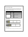
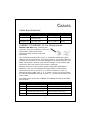
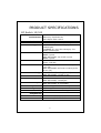
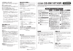
USER GUIDE SMC-EZ1016DT SMC-EZ1024DT EZ SwitchTM 10/100 16/24-port Unmanaged Fast Ethernet Switch Copyright Information furnished by LG-Ericsson USA, Inc. is believed to be accurate and reliable. However, no responsibility is assumed by LG-Ericsson USA, Inc. for its use, nor for any infringements of patents or other rights of third parties, which may result from its use. No license is granted by implication or otherwise under any patent or patent rights of LG-Ericsson USA, Inc. LG-Ericsson USA, Inc.reserves the right to change specifications at any time without notice. © Copyright 2011. LG-Ericsson USA, Inc. All rights reserved. LG-Ericsson is a registered trademark. Other products and company names are trademarks and registered trademarks of their respective holders. Technical Support To Contact LG-Ericsson Technical Support Phone: 877.828.2673 Email: [email protected] Online: http://www.lgericssonus.com Warranty and Product Registration To register LG-Ericsson products and to review the detailed warranty statement, please refer to the LG-Ericsson Website at http://www.lgericssonus.com COMPLIANCES FCC - Class A Federal Communication Commission Interference Statement This Equipment has been tested and found to comply with the limits for a Class A digital device, pursuant to part 15 of the FCC Rules. These limits are designed to provide reasonable protection against harmful interference when the equipment is operated in a commercial environment. This equipment generates, uses, and can radiate radio frequency energy and, if not installed and used in accordance with the instruction manual, may cause harmful interference to radio communications. Operation of this equipment in a residential area is likely to cause harmful interference in which case the user will be required to correct the interference at his own expense. This device complies with Part 15 of the FCC Rules. Operation is subject to the following two conditions: (1) this device may not cause harmful interference, and (2) this device must accept any interference received; including interference that may cause undesired operation. EC Conformance Declaration - Class A SMC contact for these products in Europe is: SMC Networks Europe, Edificio Conata II, Calle Fructuós Gelabert 6-8, 2o, 4a, 08970 - Sant Joan Despí, Barcelona, Spain. This information technology equipment complies with the requirements of the Council Directive 2004/108/EC on the Approximation of the laws of the Member States relating to Electromagnetic Compatibility and 2006/95/EC for electrical equipment used within certain voltage limits and the Amendment Directive 2006/95/EC. For the evaluation of the compliance with these Directives, the following standards were applied: v RFI Emission: • • • Limit class A according to EN 55022:2006 (EMC) Limit class A for harmonic current emission according to EN 61000-3-2/2000+A2:2005 Limitation of voltage fluctuation and flicker in low-voltage supply system according to EN 61000-3-3/1995+A1:2001+A2:2005 Immunity: • • • • • • • • LVD: • Product family standard according to EN 55024:1998+A1:2001+A2:2003 Electrostatic Discharge according to EN 61000-4-2:2001 ED.1.2 (Contact Discharge: ±4 kV, Air Discharge: ±8 kV) Radio-frequency electromagnetic field according to EN 61000-4-3:2006 ED.3.0 (80 - 1000 MHz with 1 kHz AM 80% Modulation: 3 V/m) Electrical fast transient/burst according to EN 61000-4-4:2004 ED.2.0(AC/DC power supply: ±1 kV, Data/Signal lines: ±0.5 kV) Surge immunity test according to EN 61000-4-5:2005 ED.2.0 (AC/DC Line to Line: ±1 kV, AC/DC Line to Earth: ±2 kV) Immunity to conducted disturbances, Induced by radio-frequency fields: EN 61000-4-6:2006 ED.2.2 (0.15 - 80 MHz with 1 kHz AM 80% Modulation: 3 V/m) Power frequency magnetic field immunity test according to EN 61000-4-8:2001 ED.1.1 (1 A/m at frequency 50 Hz) Voltage dips, short interruptions and voltage variations immunity test according to EN 61000-4-11:2004 ED.2.0(>95% Reduction @10 ms, 30% Reduction @500 ms, >95% Reduction @5000 ms) EN 60950-1:2006 vi VCCI - Class A この装置は、情報処理装置等電波障害自主規制協議会(VCCI)の基準に基づくク ラスA情報技術装置です。この装置を家庭環境で使用すると電波妨害を引き起こ すことがあります。この場合には使用者が適切な対策を講ずるよう要求されることが あります。 Please read the following safety information carefully before installing the Switch: WARNING: Installation and removal of the unit must be carried out by qualified personnel only. • • • • • • This guide is intended for use by network administrators who are responsible for setting up and installing network equipment; consequently it assumes a basic working knowledge of LANs (Local Area Networks). The unit must be connected to an earthed (grounded) outlet to comply with international safety standards. Do not connect the unit to an A.C. outlet (power supply) without an earth (ground) connection. The appliance coupler (the connector to the unit and not the wall plug) must have a configuration for mating with an EN 60320/IEC 320 appliance inlet. The socket outlet must be near to the unit and easily accessible. You can only remove power from the unit by disconnecting the power cord from the outlet. This unit operates under SELV (Safety Extra Low Voltage) conditions according to IEC 60950. The conditions are only maintained if the equipment to which it is connected also operates under SELV conditions. vii France and Peru only This unit cannot be powered from IT. supplies. If your supplies are of IT type, this unit must be powered by 230 V (2P+T) via an isolation transformer ratio 1:1, with the secondary connection point labelled Neutral, connected directly to earth (ground). †Impédance à la terre Power Cord Set U.S.A. and Canada Denmark Switzerland U.K. Europe The cord set must be UL-approved and CSA certified. The minimum specifications for the flexible cord are: - No. 18 AWG - not longer than 2 meters, or 16 AWG. - Type SV or SJ 3-conductor The cord set must have a rated current capacity of at least 10A. The attachment plug must be an earth-grounding type with NEMA 5-15P (15 A, 125 V) or NEMA 6-15P (15 A, 250 V) configuration. The supply plug must comply with Section 107-2-D1, Standard DK2-1a or DK2-5a. The supply plug must comply with SEV/ASE 1011. The supply plug must comply with BS1363 (3-pin 13 A) and be fit-ted with a 5 A fuse which complies with BS1362. The mains cord must be <HAR> or <BASEC> marked and be of type HO3VVF3GO.75 (minimum). The supply plug must comply with CEE7/7 (.SCHUKO.). The mains cord must be <HAR> or <BASEC> marked and be of type HO3VVF3GO.75 (minimum). IEC-320 receptacle. viii Veuillez lire à fond l’information de la sécurité suivante avant d’installer le Switch: AVERTISSEMENT: L.installation et la dépose de ce groupe doivent être confiés à un personnel qualifié. • • • • • Ne branchez pas votre appareil sur une prise secteur (alimentation électrique) lorsqu’il n’y a pas de connexion de mise à la terre (mise à la masse). Vous devez raccorder ce groupe à une sortie mise à la terre (mise à la masse) afin de respecter les normes internationales de écurité. Le coupleur d.appareil (le connecteur du groupe et non pas la prise murale) doit respecter une configuration qui permet un branchement sur une entrée d.appareil EN 60320/IEC 320. La prise secteur doit se trouver à proximité de l.appareil et son accès doit être facile. Vous ne pouvez mettre l.appareil hors circuit qu.en débranchant son cordon électrique au niveau de cette prise. L.appareil fonctionne à une tension extrêmement basse de sécurité qui est conforme à la norme IEC 60950. Ces conditions ne sont maintenues que si l.équipement auquel il est raccordé fonctionne dans les mêmes conditions. France et Pérou uniquement: Ce groupe ne peut pas être alimenté par un dispositif à impédance à la terre. Si vos alimentations sont du type impédance à la terre, ce groupe doit être alimenté par une tension de 230 V (2 P+T) par le biais d.un transformateur d.isolement à rapport 1:1, avec un point secondaire de connexion portant l.appellation Neutre et avec raccordement direct à la terre (masse). ix Cordon électrique - Il doit être agréé dans le pays d.utilisation Etats-Unis et Le cordon doit avoir reçu l′homologation Can-ada: des UL et un certificat de CSA. Les spe’cifications minimales pour la corde flexible sont AWG No. 18, ou AWG No. 16 pour une longueur infe’rieure a‘ 2 me’tres: - type SV ou SJ - 3 conducteurs Le cordon doit être en mesure d.acheminer un courant nominal d.au moins 10 A. La prise femelle de branchement doit être du type à mise à la terre (mise à la masse) et respecter la configuration NEMA 5-15P (15 A, 125 V) ou NEMA 6-15P (15 A, 250 V). Danemark: La prise mâle d.alimentation doit respecterla la section 107-2 D1 de norme DK2 1a ou DK2 5a. Cordon électrique - Il doit être agréé dans le pays d.utilisation Suisse: La prise mâle d.alimentation doit respecter la norme SEV/ASE 1011. Europe La prise secteur doit être conforme aux normes CEE 7/7 (.SCHU- KO. LE cordon secteur doit porter la mention <HAR> ou <BASEC> et doit être de type HO3VVF3GO.75 (minimum). x Bitte unbedingt vor dem Einbauen des RPU die folgenden Sicherheitsanweisungen durchlesen: WARNUNG: Die Installation und der Ausbau des Geräts darf nur durch Fachpersonal erfolgen. • Diese Anleitung ist fr die Benutzung durch Netzwerkadministratoren vorgesehen, die fr die Installation und das einstellen von Netzwerkkomponenten verantwortlich sind; sie setzt Erfahrung bei der Arbeit mit LANs (Local Area Networks) voraus. • Das Gerät sollte nicht an eine ungeerdete Wechselstromsteckdose angeschlossen werden. • Das Gerät muß an eine geerdete Steckdose angeschlossen werden, welche die internationalen Sicherheitsnormen erfüllt. • Der Gerätestecker (der Anschluß an das Gerät, nicht der Wandsteckdosenstecker) muß einen gemäß EN 60320/IEC 320 konfigurierten Geräteeingang haben. • Die Netzsteckdose muß in der Nähe des Geräts und leicht zugänglich sein. Die Stromversorgung des Geräts kann nur durch Herausziehen des Gerätenetzkabels aus der Netzsteckdose unterbrochen werden. • Der Betrieb dieses Geräts erfolgt unter den SELV-Bedingungen (Sicherheitskleinstspannung) gemäß IEC 60950. Diese Bedingungen sind nur gegeben, wenn auch die an das Gerät angeschlossenen Geräte unter SELV-Bedingungen betrieben werden Stromkabel. Dies muss von dem Land, in dem es benutzt wird geprüft werden: Dieser Stromstecker muß die SEV/ASE Schweiz 1011Bestimmungen ein- halten. Das Netzkabel muß vom Typ HO3VVF3GO.75 (Mindestan-forderung) sein und die Aufschrift Europe <HAR> oder BASEC> tragen Der Netzstecker muß die Norm CEE 7/7 erfüllen (.SCHUKO.). xi Warnings and Cautionary Messages Warning: This product does not contain any serviceable user parts. Warning: Installation and removal of the unit must be carried out by qualified personnel only. Warning: When connecting this device to a power outlet, connect the field ground lead on the tri-pole power plug to a valid earth ground line to prevent electrical hazards. Caution: Wear an anti-static wrist strap or take other suitable measures to prevent electrostatic discharge when handling this equipment. Caution: Do not plug a phone jack connector in the RJ-45 port. This may damage this device. Les raccordeurs ne sont pas utilisé pour le système téléphonique! Caution: Use only twisted-pair cables with RJ-45 connectors that conform to FCC standards. Warnings (in German) Achtung: Dieses Produkt enthält keine Teile, die eine Wartung vom Benutzer benötigen. Achtung: Installation und Deinstallation des Gerätes müssen von qualifiziertem Servicepersonal durchgeführt werden. Achtung: Wenn das Gerät an eine Steckdose angeschlossen wird, muß der Masseanschluß n Netzstecker mit Schutzerde verbunden werden, um elektrische Gefahren zu vermeiden. Warnings (in Korean) A 급기기 (업무용 정보통신기기) 이 기기는 업무용으로 전자파 등록을 한 기기 이오니 판매자 또는 사용자는 이 점을 주의 하시기 바라며, 만약 잘못 판매 또는 구입하였을 때에는 가정용으로 교환하시기 바랍니다. xii Environmental Statement The manufacturer of this product endeavors to sustain an environmentally-friendly policy throughout the entire production process. This is achieved though the following means: • Adherence to national legislation and regulations on environmental production standards. • Conservation of operational resources. • Waste reduction and safe disposal of all harmful un-recyclable by-products. • Recycling of all reusable waste content. • Design of products to maximize recyclables at the end of the product’s life span. • Continual monitoring of safety standards. End of Product Life Span This product is manufactured in such a way as to allow for the recovery and disposal of all included electrical components once the product has reached the end of its life. Manufacturing Materials There are no hazardous nor ozone-depleting materials in this product. Documentation All printed documentation for this product uses biodegradable paper that originates from sustained and managed forests. The inks used in the printing process are non-toxic. Purpose This guide details the hardware features of the switch, including Its physical and performance-related characteristics, and how to install the switch. Audience The guide is intended for use by network administrators who are responsible for installing and setting up network equipment; consequently, it assumes a basic working knowledge of LANs (Local Area Networks). Diese Anleitung ist für die Benutzung durch Netzwerkadministratoren vorgesehen, die für die Installation und das einstellen von Netzwerkkomponenten verantwortlich sind; sie setzt Erfahrung bei der Arbeit mit LANs (Local Area Networks) voraus. xiii TABLE OF CONTENTS INTRODUCTION.................................. 2 Green Saving Switches…………………………………………….2 Features and Benefits ....................................... 2 Front Panel LEDs .............................................. 4 Front Panel ...................................................... 4 Rear Panel ....................................................... 4 INSTALLING THE SWITCH .................... 5 Package Contents ............................................. 5 Selecting a Site ................................................ 5 Instructions ..................................................... 6 TROUBLESHOOTING ........................... 7 Diagnosing Switch Indicators ............................. 7 CABLES ............................................. 8 Cable Specifications .......................................... 8 10BASE-T/100BASE-TX Pin Assignments ............. 8 PRODUCT SPECIFICATIONS ................. 9 INTRODUCTION The EZ Switch™ 10/100 SMC-EZ1016DT and SMC-EZ1024DT are 16/24-port Fast Ethernet switches. The 10BASE-T/100BASE-TX ports deliver dedicated 10/100 Mbps links to each attached LAN segment – all with conventional cabling and adapters. Auto-negotiation is used to select the optimal communication mode for each connection. Auto-sensing is used to select the optimal transmission speed for each connection. With store-and-forward switching and flow control, maximum data integrity is always maintained, even under heavy loading. Easy installation and reliability make this plug-and-play switch an ideal choice for smooth Fast Ethernet integration. Green Saving Switches The Green Saving technologies are intelligent, innovative algorithms that detect link status and distance to best save power while maintaining performance and stability. l Power saving by Auto-Detection of the number of active ports: The SMC-EZ1016DT/SMC-EZ1024DT switches will auto-detect the link status and automatically cut off power at a given port during periods of idle (when a port is unconnected or a PC is turned off). After it detects an incoming signal, it wakes up from power saving mode and operates in normal mode. l Power saving by Cable length Auto-Detection: The SMC-EZ1016DT/SMC-EZ1024DT switches can actively detect the presence of a shorter cable and determines the appropriate power level based on cable length so there’ll be less power consumption when the link distance is shorter. 2 Features and Benefits • Save up to 59% of power usage with the SMC-EZ1016DT/SMC-EZ1024DT switches - If PCs connected to the switches are turned off, the switches can save up to 59% for the power used. And even under full traffic load, the switches can still save up to 21% power consumption. - If cable length is less than 20 meters, each switch can save up to 12% for the power used. • Auto-negotiation of half or full duplex, and auto-sensing of transmission speed, on all ports • Auto configuration for MDI/MDI-X cable connection allows connections to servers, workstations, hubs or switches to be made with straight-through cabling • ANSI/IEEE 802.3u compliance ensures compatibility with standards-based hubs, switches and cards from any vendor • Store-and-forward switching ensures error-free transmission • Half- and full-duplex flow control prevents packets from being dropped under heavy loading • Plug-and-play • “At-a-glance” LEDs for port and system status monitoring • Desktop and rack mountable 3 Front Panel LEDs The front panel of the switch provides a link status LED for each RJ-45 port. In addition, the front panel also contains status LEDs for “at-a-glance” system monitoring. The following table details the functions of the various indicators: Port and Switch Status LEDs LED Condition Status Power On Green The switch is receiving power. On The port has established a valid network connection. Traffic is passing through the port. The port has not established any network connection. Ports Link/Act Flashing Off Front Panel SMC-EZ1024DT SMC-EZ1016DT Rear Panel The AC power connector is located on the rear panel of the switch. 4 INSTALLING THE SWITCH Before installing the switch, verify that you have all the items listed under “Package Contents.” Note that the switch can be installed on any suitably large flat surface or in a standard EIA 19-inch rack. Package Contents The EZ Switch 10/100 includes: • • • • • EZ Switch 10/100 (SMC-EZ1016DT or SMC-EZ1024DT) Four rubber foot pads Rack-mount bracket kit Appropriate AC power cord This User Manual Selecting a Site Be sure to follow the site selection guidelines below when choosing a location: • • • Select a suitable location for the switch: o It should be accessible for installing, cabling and maintaining the switch. o The temperature and humidity should be within the ranges listed in the specifications. o The status LEDs should be clearly visible. o There should be adequate space (approximately two inches) on all sides for proper air flow. Make sure twisted-pair cable is always routed away from power lines, fluorescent lighting fixtures and other sources of electrical interference such as radios, transmitters, etc. Make sure that a properly grounded power outlet is within 2.44 meters (8 feet) of the switch and is powered from an independent circuit breaker. As with any equipment, using a filter or surge suppressor is recommended. 5 Instructions 1. Positioning the Switch: For desktop or shelf mounting, attach the four adhesive foot pads to the bottom of the switch. For rack mounting, install into a standard EIA 19-inch rack using the included brackets. 2. Applying Power: Plug one end of the power cord into the socket on the switch’s rear panel, and the other end into an appropriate electrical outlet. Check the Power LED to be sure power is on. Note: It is not necessary to power off the switch before connecting or disconnecting any UTP cables, as these actions will not disrupt the operation of other devices attached to the switch. 3. Connecting PCs: Connect each PC to an RJ-45 port on the switch using Category 5 or 5e shielded or unshielded twisted-pair (UTP or STP) cable, maximum length 100 meters (328 ft). The EZ Switch 10/100 will support up to 16 or 24 PCs. All ports on the switch support automatic MDI/MDI-X operation, so you can use straight-through cables for all network connections to PCs or servers, or to other switches or hubs. Note: If an attached device does not support auto-negotiation, the data rate will be sensed automatically and the communication mode will default to half duplex. 4. Cascading Switches and Other Network Devices: All the ports on the switch support automatic MDI/MDI-X configuration for cable connections. This allows you to use straight-through cable to connect to other switches or hubs from any port on the switch. No crossover cables or other device settings are needed. See the Cable Specifications. Caution: Do not plug a phone jack connector into any RJ-45 port. This switch, instead, use only twisted-pair cables with RJ-45 connectors that conform with FCC standards. 6 TROUBLESHOOTING Diagnosing Switch Indicators 1. Symptom Power LED does not light after power on. Probable Causes o AC power cord may be defective. Possible Solutions o Check for loose connections. o Check the power outlet by using it for another device. o Replace the AC power cord. 2. Symptom Link LED does not light after connection is made. Probable Causes o Switch port, network card or cable may be defective. Possible Solutions o Check that the switch and attached device are both powered on. o Be sure the network cable is connected to both devices. o Verify that Category 5 or better cable is used for 10/100 Mbps connections and that the length of any cable does not exceed 100 meters (328 feet). o Check the network card and cable connections for defects. o Replace the defective card or cable if necessary. 7 CABLES Cable Specifications Cable 10BASE-T 100BASE-TX Cable Types and Specifications Type Max. Length 2-pair Cat. 3 or better 100 m (328 ft) 100-ohm UTP 2-pair Cat. 5 or better 100 m (328 ft) 100-ohm UTP Connector RJ-45 RJ-45 10BASE-T/100BASE-TX Pin Assignments Caution: DO NOT plug a phone jack connector into any RJ-45 port. Use only twisted-pair cables with RJ-45 connectors that conform with FCC standards. Use unshielded twisted-pair (UTP) or shielded twisted-pair (STP) cable for RJ-45 connections: 100-ohm Category 3 or better cable for 10 Mbps connections or 100-ohm Category 5 or better cable for 100 Mbps connections. Also be sure that the length of any twisted-pair connection does not exceed 100 meters (328 feet). Because all ports on this switch support automatic MDI/MDI-X operation, you can use straight-through cables for all network connections to PCs or servers, or to other switches or hubs. In straight-through cable, pins 1, 2, 3, and 6, at one end of the cable, are connected straight through to pins 1, 2, 3 and 6 at the other end of the cable. The table below shows the 10BASE-T/100BASE-TX MDI-X and MDI port pinouts. Pin MDI-X Signal Name MDI Signal Name 1 Receive Data plus (RD+) Transmit Data plus (TD+) 2 Receive Data minus (RD-) Transmit Data minus (TD-) 3 Transmit Data plus (TD+) Receive Data plus (RD+) 6 Transmit Data minus (TD-) Receive Data minus (RD-) 4,5,7,8 Not used at 10/100 Mbps Not used at 10/100 Mbps 8 PRODUCT SPECIFICATIONS EZ Switch 10/100 Standards Conformance Communication Rate Communication Mode Media Supported Number of Ports Indicator Panel Dimensions Weight MAC Address Table Memory Buffer Power Consumption Power Requirement Temperature Humidity EMC/Safety Compliances Immunity Emissions IEEE 802.3-2002 Ethernet, Fast Ethernet Full-duplex flow control 10 and 100Mbps Full or half duplex at 10/100 Mbps 10BASE-T: 100-ohm Category 3 or better twisted-pair 100BASE-TX: 100-ohm Category 5 or better twisted pair SMC-EZ1016DT: 16 RJ-45 10/100 BASE-T ports SMC-EZ1024DT: 24 RJ-45 10/100 BASE-T ports Power Ports: Link/Act SMC-EZ1016DT:21.6x13.3x4.2cm(8.5x5 .2x1.7in) SMC-EZ1024DT:26.7x16.1x4.2cm(10.5x 6.3x1.7in) SMC-EZ1016DT: 870g (1.9 lbs) SMC-EZ1024DT: 1376g (3 lbs) 8 K entries SMC-EZ1016DT: 160Kbytes SMC-EZ1024DT: 160Kbytes SMC-EZ1016DT: 6.831 Watts SMC-EZ1024DT: 8.514 Watts Input Voltage: 100 - 240 VAC@50-60 Hz Operating: 0 ~ 40 ºC / 32 ~ 104 ºF 10% to 90% non-condensing CE Mark EN 61000-4-2/3/4/5/6/8/11 FCC Class A,VCCI Class A 9 Warranty Information and Product Registration To register LG-Ericsson products and to review the detailed warranty statement, please refer to the LG-Ericsson Website at http://www.lgericssonus.com Technical Support To Contact LG-Ericsson Technical Support Phone: 877.828.2673 Email: [email protected] Online: http://www.lgericssonus.com Copyright Information furnished by LG-Ericsson USA, Inc. is believed to be accurate and reliable. However, no responsibility is assumed by LG-Ericsson USA, Inc. for its use, nor for any infringements of patents or other rights of third parties, which may result from its use. No license is granted by implication or otherwise under any patent or patent rights of LG-Ericsson USA, Inc. LG-Ericsson USA, Inc. reserves the right to change specifications at any time without notice. © Copyright 2011. LG-Ericsson USA, Inc. All rights reserved. LG-Ericsson is a registered trademark. Other products and company names are trademarks and registered trademarks of their respective holders. Model Number SMC6128L2 SMC-EZ1016DT SMC-EZ1024DT EZ SwitchTM 10/100 16/24-port Unmanaged Fast Ethernet Switch