1
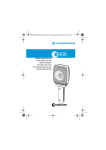
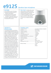
e 912 S_516585_0207_Sp6.book Seite 1 Freitag, 28. September 2007 11:09 11
912 S
Bedienungsanleitung
Instructions for use
Notice d‘emploi
Istruzoni per l‘uso
Instrucciones de uso
Gebruiksaanwijzing
e 912 S_516585_0207_Sp6.book Seite 2 Freitag, 28. September 2007 11:09 11
e 912 S_516585_0207_Sp6.book Seite 1 Freitag, 28. September 2007 11:09 11
912 S
The boundary microphone
912 S is a high-quality, prepolarized condenser microphone with half-cardioid pick-up
pattern, designed for picking up speech.
Due to its unobtrusive, flat design, it is ideally suited for use on
conference tables, altars and lecterns.
The microphone can be switched on and off via an integrated
membrane switch.
An internal DIP switch bank provides the following operating
modes:
y
y
y
y
On/off (factory preset)
Push-to-talk button (PTT)
Push-to-mute button (PTM)
Permanently switched on
The frequency response curve can be changed via a second DIP
switch bank:
y
y
y
y
Low cut
Low and high boost (factory preset)
Low boost
linear (= frequency response curve of the
912)
The
912 S is available in three different finishes:
y
y
y
912 S BK (black)
Cat. No. 500875
912 S WH (white)
Cat. No. 500876
912 S NX (Nextel non-reflecting gray) Cat. No. 502193
1
e 912 S_516585_0207_Sp6.book Seite 2 Freitag, 28. September 2007 11:09 11
Features
y
y
y
y
y
y
y
y
Programmable membrane switch
Programmable frequency response curve
Very unobtrusive due to flat design
Extremely rugged sound inlet basket
Rubber damping plate on base to minimize structure-born
noise
Mounting slots for mounting the microphone to table tops,
lecterns, etc.
Gold-plated XLR connector
Integrated electronics (instead of in-line preamp)
Delivery includes
y
912 S boundary microphone
y Pouch
y Instructions for use
y Warranty Certificate
2
e 912 S_516585_0207_Sp6.book Seite 3 Freitag, 28. September 2007 11:09 11
Postioning the microphone
Boundary microphones make use of the pressure effects at a
room boundary and need to be mounted on a flat surface:
Position
Sound result
Comments
Altar or lectern:
Less room resonance
on a sound-reflecting portions or comb filter
elements; improved
surface
speech intelligibility
and greater gain
reserves in contrast to
freestanding microphones
Unobtrusive due to
flat design; no microphones in the field of
vision
Conference rooms:
lying on the table;
directed towards the
conference
participants *)
Microphones must
not be covered by
papers, folders or
similar objects
Less room resonance
in contrast to
freestanding
microphones
*) The cardioid pick-up pattern has an opening angle of approx.
130°. Try to position the microphone so that the sound source
(conference participant, speaker or instrument) is located in
this angle area (see polar diagram).
3
e 912 S_516585_0207_Sp6.book Seite 4 Freitag, 28. September 2007 11:09 11
Setting the operating mode and frequency
response curve
쐃
쐇
DIP switch bank:
(visible when rear side
is open)
쐃 Operating mode
쐇 Frequency response curve
Position of
DIP switches
1 2 3 4
1 2 3 4
1 2 3 4
1 2 3 4
4
Operating
mode 쐃
Permanently
switched on (ON)
Push-to-talk
button (PTT)
Push-to-mute
button (PTM)
On/off (factory
preset)
Position of
DIP switches
1 2 3 4
Frequency
response curve 쐇
Low cut, can be
used in all
operating modes
Low boost
1 2 3 4
1 2 3 4
Low and high
boost (factory
preset)
linear
1 2 3 4
e 912 S_516585_0207_Sp6.book Seite 5 Freitag, 28. September 2007 11:09 11
Operating Mode 쐃:
y Permanently switched on:
y
y
y
disables the switch completely, the microphone is
permanently switched on.
Push-to-talk (PTT):
The microphone is switched on as long as the membrane
switch is pressed.
Push-to-mute (PTM):
The microphone is switched off as long as the membrane
switch is pressed.
On/off (factory preset):
turns the switch into push to switch on, push again to switch
off.
Frequency response curve 쐇:
y Low cut:
y
y
y
reduces the bass frequencies to minimize structure-born
noise – this switch (1) is independent of the other three DIP
switches and can be used in any of the following conditions
(eg: you can use the low cut as well as the bass boost if
placing the microphone on a small table with a high risk of
structure-born noise).
Low boost:
extends the bass response to compensate for putting the
microphone on a small table.
Low and high boost (factory preset):
extends the frequency response at both ends.
Linear:
is the natural response of the microphone.
5
e 912 S_516585_0207_Sp6.book Seite 6 Freitag, 28. September 2007 11:09 11
Polar diagram
6
e 912 S_516585_0207_Sp6.book Seite 7 Freitag, 28. September 2007 11:09 11
Frequency response curve
dBv
- 30
- 40
- 50
- 60
- 70
- 80
20
50
100
200
500 1000 2000
5000 10000 20000 Hz
Low and high boost (factory preset)
Rumble filter (low cut)
dBv
- 30
- 40
- 50
- 60
- 70
- 80
20
50
100
200
500 1000 2000
5000 10000 20000 Hz
Linear ( 912)
Low boost
7
e 912 S_516585_0207_Sp6.book Seite 8 Freitag, 28. September 2007 11:09 11
Specifications
Transducer principle
pre-polarized condenser
microphone
Frequency response
20 – 20,000 Hz
Pick-up pattern
half-cardioid
Sensitivity (free field, no load)
(1 kHz)
6 mV/Pa (factory preset)
10 mV/Pa (lin)
Nominal impedance (1 kHz)
<100 Ω
Min. terminating impedance
1 kΩ
Phantom powering
48 V/2.8 mA
Max. sound pressure level (1 kHz) 134 dB SPL
Connector
XLR-3
Weight
550 g
Dimensions
L: 126.5 mm
W: 105 mm
H: 26.5 mm
Pin assignment of XLR-3 connector
+
+
2
1
3
XLR
8
1
2
+
+
2
1
3
3
XLR
XLR
e 912 S_516585_0207_Sp6.book Seite 9 Freitag, 28. September 2007 11:09 11
Vocals
x
Choirs
Studio, acoustic
instruments
x
x
x
x
x
Orchestra
x
Trumpet, trombone
x
x
Saxophone
x
x
x
x
Acoustic guitar
x
Acoustic bass
x
Guitar amplifiers
x
Bass amplifiers
Leslie
x
x
x
x
x
x
x
Piano, grand piano
Kick drums
x
Snare drums
x
x
x
Rack toms
x
x
x
x
x
x
Floor toms
Congas
x
x
x
x
x
x
x
x
x
x
x
x
x
Cymbals
Percussion
e935/e945
e914
e912 S
e912
e908T ew
e908D
e908B
e906
e905
e904
e902
Application
e901
Variant
e908B ew
Overview of microphone applications
x
x
x
x
Conference table,
altar
x
x
Lectern
x
x
Theater stage
x
x
9
e 912 S_516585_0207_Sp6.book Seite 10 Freitag, 28. September 2007 11:09 11
Manufacturer Declarations
Warranty
2 years
CE Declaration of Conformity
Sennheiser electronic GmbH & Co. KG declare that this
device is in compliance with the applicable CE
standards and regulations.
WEEE Declaration
Please dispose of this product by bringing it to your
local collection point or recycling centre for such
equipment.
10
e 912 S_516585_0207_Sp6.book Seite 1 Freitag, 28. September 2007 11:09 11
Sennheiser electronic GmbH & Co. KG
30900 Wedemark, Germany
Phone +49 (5130) 600 0
Fax +49 (5130) 600 300
www.sennheiser.com
Printed in Germany
Publ. 09/07
516585/A03