1
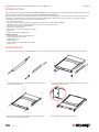
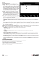
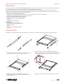
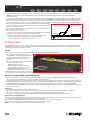
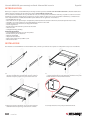
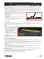
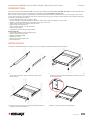
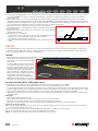
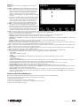
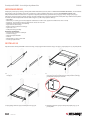
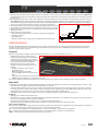
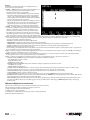
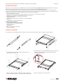
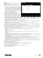
8-Port
Rackmount
LCD Console
KVM Switch
user manual
Model 506540
INT-506540-UM-ML1-0710-03-0
Rackmount LCD Console KVM Switch • User Manual English
INTRODUCTION
Thank you for purchasing the INTELLINET NETWORK SOLUTIONS™ 8-Port Rackmount LCD Console KVM Switch, Model 506540. For a full
list of specifications, refer to the datasheet available at www.intellinet-network.com.
With the industry-standard 19” 1U-height rack drawer, this switch can be easily pulled out and accessed in the extended position, and
the display can be folded down, locked and secured when stored. With the ability to manage and control up to eight PS/2 or USB
computers, you’ll also be able to enjoy these convenient features:
• Easy-to-use OSD interface
• Flip-open 17 inch LCD panel (2048 x 1536 highest resolution; 1280 x 1024 optimal resolution)
• Adjustable for rack cabinets with depths from 600 mm to 1200 mm (23.6 to 47 in.)
• Full 105-key, low-profile, sturdy keyboard
• Ergonomic handrest design
• Ultra-sturdy rear bracket and extension design
• Auto Scan
• Plug and Play system configuration
Package Contents
• 8-Port Rackmount LCD Console KVM Switch
• Rear bracket and extension kit
• KVM switch module
• Power adapter
• Eight 1.8 m (6 ft.) PS/2 and USB combo cables
• User manual
INSTALLATION
To install the Rackmount LCD Console KVM Switch in a rack unit, begin by removing the brackets if the device is already assembled.
1.For both the left and right bracket assemblies, screw the front
of the bracket to the rack, then extend the bracket and attach
it to the back of the rack.
2.Carefully place the switch on the mounted brackets and
loosely attach the front of the switch to the front of the rack
using the included screws.
3.Move the rear attachment brackets along the slide bars until
they contact the back of the switch.
4.Attach the bars to the back of the switch.
2
ENGLISH
12 VDC
5.Using the included power adapter, connect the 12 VDC jack on the rear panel of the switch module (above) to an A/C outlet. NOTE: When the control platform is pulled out to its full extension, the bracket guides lock automatically and the power is turned on to the
console.
6.Using the included 1.8 m combo cables, connect the HD15 port connectors on the rear panel of the switch module either to PS/2 ports
or to USB ports on the computers to be included in the configuration. NOTE: The Rackmount LCD Console KVM Switch features hot- swap capability: Computers can be connected and disconnected without turning off the switch. Be sure, however, that the control
platform is powered on before powering on any of the connected computers, and always plug in the mouse before the keyboard.
7.To open the control platform and display the LCD screen, squeeze the handle
Front handle lock
to release the front lock and lift up. The LCD panel can be tilted back as far as
120 degrees.
8.Press the red Power button on the console (see Operation) to turn the LCD
screen on.
9. When shutting down the switch:
• Press the red Power button on the console to turn the LCD screen off.
AUTo loCK
• Close the LCD panel so the front handle locks.
Auto lock
• Release the guide lock on the side of the bracket assembly.
• Gently push the control platform all the way in to the rack so the power is
UNloCK
Unlock
turned off to the switch.
OPERATION
The Rackmount LCD Console KVM Switch allows you to select and monitor up to eight connected computers two ways: by simply
pressing corresponding buttons or by using a mouse or the touch pad to navigate through the on-screen display (which also provides
access to the majority of the control and configuration options).
Buttons
Using the buttons is quick and easy, as they are positioned just above the keyboard on the control platform.
• In the highlighted grouping on the right are
the PC1 through PC8 buttons used to select
and monitor a connected computer, plus the
red RESET button, which allows you to
re-boot.
• In the highlighted grouping on the left are
another six buttons (from left to right):
- AUTO adjusts the LCD display.
- MENU displays the OSD main menu.
- LEFT and RIGHT re-position the LCD image.
- EXIT leaves the currently displayed screen.
- POWER (red) turns the LCD on and off.
Also located on the control platform is the
touch pad (below the space bar), which can be used instead of a mouse for on-screen navigation.
On-Screen Display (OSD)
All computer control and switching procedures can be performed using the On-Screen Display (OSD).
• To display the main menu, press <Scroll Lock> on the keyboard twice.
• If the OSD menu is set as “Console locked,” you need to input a password each time the main menu appears. If no password has been
set, just press <Enter> to display the main menu. There are two passwords in the OSD: the user password, which is not pre-set; and the
factory password, which is “INTELLINET.”
• The OSD always starts at the List screen, with the highlight bar in the same position as when the OSD was exited.
Navigation
• To exit the OSD, press <Esc>.
• To move up and down through the menu one line at a time, use the Up and Down Arrow keys. If there are more listed entries than what
can appear on the main screen, the screen will scroll.
• To activate a port, move the highlight bar to it and press <Enter>.
• After you select a port, the OSD menu automatically disappears and the port currently selected is indicated.
Main Screen Headings
PN — This column lists the port numbers for all the CPU ports on the installation. The simplest way to access a particular computer is to
move the highlight bar to it, then press <Enter>.
QV — If a port has been selected for Quick View scanning,4 displays in this column.
PC — If a computer is powered on and on line,4 displays in this column.
NAME — Any name assigned to a computer appears in this column.
ENGLISH
3
Functions
The OSD can be controlled and re-configured using the
functions described below.
F1 GOTO — GOTO allows you to switch directly to a port by
keying in either the computer’s name or its port number (PN).
• To use the name, highlight “NAME,” press <Enter>, input
the name of the computer, then press <Enter> to confirm.
If there is a matching name, it will display on the screen.
Press <Enter> to switch to that port.
• To use PN method, highlight “PN,” press <Enter>, input the
port number, then press <Enter> to switch. If the port
number is invalid, it will prompt you to try again.
• To return to the main menu, press <Esc>.
F2 SCAN — This allows you to automatically scan from the
current selected port through any active and connected
computers. While scanning, a small window on the screen
indicates the current port number. To stop scanning (and
continue viewing the last computer scanned), press the
space bar. The scan interval can be set by the user.
F3 LIST — This lets you broaden or narrow the range of ports
displayed on the main screen. Many of the OSD functions
described below only operate on the computers listed on the main screen (selected by using this function).
• ALL lists all of the ports in the configuration.
• QVIEW lists only the ports that have been selected as Quick View ports.
• POWERED ON lists only the ports that have their attached computers powered on.
• POWERED ON + QVIEW lists only the ports that have their attached computers powered on and have been selected as Quick View ports.
• QVIEW + NAME lists only the ports that have been selected as Quick View ports and have been assigned names.
• NAME lists only the ports that have been assigned names.
Highlight a function and press <Enter>. When the confirmation icon displays alongside your selection, press <Enter> to return to the OSD main screen with the newly formulated list displayed.
F4 QV — This lets you select a port as Quick View. Highlight a port and press <F4>. The s icon displays to confirm your selection. Press
<F4> again and the icon disappears.
F5 EDIT — This lets you create or edit the name of a port. Press <F5> and a pink edit box will appear on the screen. Input a name, press
<Enter>, and the port name will be set and displayed.
F6 SET — This lets you configure the OSD menu. Highlight an option and press <Enter> to change settings.
• CHANNEL DISPLAY MODE offers three options for what appears in the tip window:
- PN + NAME
- PN (port number only)
- NAME
• CHANNEL DISPLAY DURATION offers two options for the length of time the tip window remains on the screen:
- 3 SECONDS
- ALWAYS ON
• CHANNEL DISPLAY POSITION lets you re-position the tip window. When the window appears on the screen, use the arrow keys to move it, then press <Enter> to set the new position.
• SCAN DURATION offers eight options for the amount of time each connected computer is scanned, ranging from 3 to 60 seconds.
• SET PASSWORD lets you change the current password as directed on screen.
• CLEAR THE NAME LIST lets you remove any names assigned to the ports. NOTE: This requires a password.
• RESTORE DEFAULT VALUE lets you return to the default settings. NOTE: This requires a password. The user password will be cleared,
but not the factory password.
• LOCK CONSOLE means you cannot switch or scan once this function is activated (neither by using the PC1–PC8 push buttons on the
keyboard nor the OSD). Selecting this same option when the console is locked will unlock it. NOTE: Both of these options require a
password.
Power On/Off and Reboot
When you’re ready to stow the switch after use, follow the steps in Step 9 of Installation.
If you need to cut power to the control platform; for example, to reboot:
1.Turn off the power to all connected computers.
2.Disconnect the power adapter from the switch.
3.After 10 seconds or more, re-connect power to the switch and turn it on.
4.Turn on the connected computers.
4
ENGLISH
KVM Switch mit Konsole • Handbuch Deutsch
EINLEITUNG
Vielen Dank für den Kauf des INTELLINET NETWORK SOLUTIONS™ 8-Port 19“ KVM Switch mit Konsole, Modell 506540. Das Datenblatt mit
einer vollständigen Liste aller Spezifikationen finden Sie auf www.intellinet-network.com.
Durch die Rack-Schublade in der 19”/1 HE-Bauform, kann dieser Switch leicht ein- und ausgefahren werden, der Bildschirm kann
eingeklappt und sicher verschlossen werden. Neben der Möglichkeit bis zu acht PS/2- oder USB-Computer zu verwalten und zu steuern,
haben Sie außerdem Zugriff auf die folgenden Eigenschaften:
• OSD-Interface (Interaktives Bildschirmmenü)
• Aufklappbarer 17-Zoll-LCD-Bildschirm (2048 x 1536 max. Auflösung; 1280 x 1024 optimale Auflösung)
• Verstellbar - für Racks mit einer Tiefe von 600 mm bis 1200 mm
• Inklusive robuster und flacher 105-Tasten-Tastatur
• Ergonomisches Design mit Handballenauflage
• Einbaurahmen und -schienen äußerst robust
• Autoscan
• Plug&Play-Systemkonfiguration
Lieferumfang
• 8-Port 19” KVM Switch mit Konsole
• Einbaurahmen und Erweiterungszubehör
• KVM-Switch-Modul
• Netzteil
• Acht 1,8 m PS/2- und USB-Kombikabel
• Handbuch
INSTALLATION
Befestigen Sie den KVM-Switch auf einer Rack-Einheit. Ist der Switch bereits montiert, entfernen Sie zunächst seine Einbaurahmen.
1.Schrauben Sie zunächst den vorderen Teil des linken und
rechten Einbaurahmens fest, dann fahren Sie die Rahmen aus
und befestigen sie auf der hinteren Seite des Racks.
2.Platzieren Sie den Switch vorsichtig auf dem montierten
Rahmen und befestigen Sie den vorderen Teil des Switches mit
den beiliegenden Schrauben locker am vorderen Teil des Racks.
3.Schieben Sie die hinteren Befestigungselemente der
Einbaurahmen entlang der Schiene, bis sie die Rückseite des
Switches berühren.
4.Befestigen Sie diese Elemente an der Rückseite des Switches.
DEUTSCH
5
5.Schließen Sie das beiliegende Netzteil an die 12 V DC-Buchse auf der Rückseite der Konsole (siehe oben) sowie an eine Steckdose an.
HINWEIS: Ist die Konsole vollständig ausgefahren, rastet der Ausziehmechanismus ein, woraufhin die Konsole automatisch
eingeschaltet wird.
6.Schließen Sie die beiliegenden 1,8-m-Kombikabel an die HD15-Ports auf der Rückseite des Switch-Moduls an sowie entweder an PS2/ oder USB-Ports der Computer, die Sie vom Switch aus bedienen möchten. HINWEIS: Dieser KVM-Switch ist Hot-Swap-fähig: Computer
können angeschlossen und getrennt werden, ohne dass der Switch ausgeschaltet werden muss. Achten Sie aber darauf, dass die
Konsole eingeschaltet ist, bevor Sie einen der angeschlossenen PCs einschalten und schließen Sie die Maus immer vor der Tastatur an.
7.Um die Konsole zu öffnen, drücken Sie auf den Verschluss, um die Verriegelung
Abdeckungsverschluss
zu lösen und .klappen Sie die Konsole auf. Das Display kann bis zu 120 Grad
nach hinten geklappt werden.
8.Drücken Sie die rote Power-Taste auf der Konsole (siehe nächster Abschnitt),
um das Display einzuschalten.
9. Wenn Sie den Switch ausschalten:
• Drücken Sie die rote Power-Taste der Konsole, um das Display auszuschalten.
Automatische
AUTo loCK
• Schließen Sie die Konsole, so dass der Verschluss einrastet.
Einrastung
• Lösen Sie die Schienenverriegelung an der Seite des Einbaurahmens.
• Schieben Sie die Konsole vollständig in das Rack, so dass die
UNloCK
Entriegeln
Stromversorgung zum Switch abgeschaltet wird.
VERWENDUNG
Dieser KVM-Switch lässt Sie bis zu acht angeschlossene Computer auf zwei Arten auswählen und bedienen: Indem Sie einfach auf die
zugeordnete Taste drücken oder indem Sie per Maus und Touchpad das Bildschirmmenü nutzen (welches auch Zugriff auf die meisten
Steuerungs- und Einstellungsoptionen bietet).
Tasten
Diese Tasten können bequem bedient werden, da sie sich direkt über der Haupttastatur befinden.
• Die eingekreisten Tasten auf der rechten
Seite bezeichnen PC1 bis PC8, die zur Auswahl
der angeschlossenen PCs dienen sowie die
rote RESET-Taste, mit der Sie neu starten
können.
• Die sechs eingekreisten Tasten auf der linken
Seite (von links nach rechts):
- AUTO stellt das Display ein.
- MENU blendet das Hauptmenü ein.
- LEFT und RIGHT positionieren das Bild.
- EXIT verlässt das aktuelle Menü.
- POWER (rot) schaltet das Display ein und aus.
Außerdem befindet sich unterhalb der Tastatur
das Touchpad, das statt der Maus für die Steuerung des Bildschirmmenüs verwendet werden kann.
On-Screen Display (OSD) - Bildschirmmenü
Die gesamte PC-Steuerung und alle Switching-(Umschalt-) Eingaben können über das Bildschirmmenü durchgeführt werden.
• Um das Hauptmenü einzublenden, drücken Sie zweimal die Taste <Rollen>.
• Ist das Bildschirmmenü auf “Console locked” eingestellt, müssen Sie bei jedem Gang ins Hauptmenü ein Passwort eingeben. Sollte kein
Passwort benötigt werden, drücken Sie einfach <Enter>, um das Hauptmenü einzublenden. Es gibt zwei Passwörter im Bildschirmmenü:
das Benutzerpasswort, das nicht voreingestellt ist und das Passwort aus den Werkseinstellungen. Dieses lautet “INTELLINET.”
• Das Bildschirmmenü startet mit einer Liste, in der sich der Auswahlbalken immer an der selben Stelle wie zum Zeitpunkt des Verlassens
des Menüs befindet.
Navigation
• Um das Bildschirmmenü zu verlassen, drücken Sie <Esc>.
• Um sich im Menü jeweils einen Schritt nach oben oder unten zu bewegen, verwenden Sie die entsprechenden Pfeiltasten.
• Um einen Port zu aktivieren, markieren Sie ihn mit dem Auswahlbalken und drücken Sie dann <Enter>.
• Haben Sie einen Port ausgewählt, wird das Bildschirmmenü automatisch ausgeblendet und der Port angezeigt.
Kategorien des Hauptbildschirms
PN — Listet die Portnummern für alle CPU-Ports der Installation auf. Der einfachste Weg, um einen bestimmten PC auszuwählen ist ihn
mit dem Auswahlbalken zu markieren und dann <Enter> zu drücken.
QV — Ein Port wurde für Quick View (Vorschauansicht) ausgewählt4 wird in dieser Spalte angezeigt.
PC — Ein PC ist eingeschaltet und verbunden4 wird in in dieser Spalte angezeigt.
NAME — Der dem PC zugeteilte Name wird in dieser Spalte angezeigt.
6
DEUTSCH
Functions
Das Bildschirmmenü kann mit den unten stehenden Funktionen
bedient und konfiguriert werden.
F1 GOTO — Schalten Sie direkt zu einem bestimmten Port um,
indem Sie entweder den PC-Namen oder dessen
Portnummer (PN) eingeben.
• Um den Namen zu verwenden, markieren Sie “NAME,”
drücken Sie <Enter>, geben Sie den Namen des PCs ein,
dann drücken Sie erneut <Enter>. Gibt es einen
entsprechenden Namen, wird dieser angezeigt. Drücken
Sie <Enter>, um zu diesem Port umzuschalten.
• Um die Portnummer zu verwenden, markieren Sie “PN,”
drücken Sie <Enter>, geben Sie die PN ein, dann drücken
Sie erneut <Enter>. Ist die PN ungültig, werden Sie zur
erneuten Eingabe aufgefordert.
• Um zum Hauptmenü zurückzukehren, drücken Sie <Esc>.
F2 SCAN — Scannt vom aktuell ausgewählten Port aus nach
aktiven und angeschlossenen PCs. Während der Suche zeigt
ein kleines Fenster die aktuelle Portnummer. Um den Scan
abzubrechen, (und mit dem letzten gefundenen PC
fortzufahren), drücken Sie die Leertaste. Das Scanintervall
kann durch den Nutzer festgelegt werden.
F3 LIST — Bestimmt die Anzahl der auf dem Hauptbildschirm angezeigten Ports. Viele der im Folgenden beschriebenen Bildschirmfunktionen
können nur mit auf dem Bildschirm angezeigten PCs verwendet werden (diese werden mit dieser Funktion ausgewählt).
• ALL zeigt die Ports aller angeschlossenen PCs.
• QVIEW zeigt die Ports, die mit Vorschauansicht ausgewählt wurden.
• POWERED ON zeigt nur die Ports, deren PCs eingeschaltet sind.
• POWERED ON + QVIEW zeigt nur die Ports, deren PCs eingeschaltet sind und mit Vorschauansicht ausgewählt wurden .
• QVIEW + NAME zeigt nur die Ports, die mit Vorschauansicht ausgewählt wurden und denen Namen zugeteilt wurden.
• NAME zeigt nur die Ports, denen Namen zugeteilt wurden.
Markieren Sie eine Funktion und drücken Sie <Enter>. Wenn das Bestätigungssymbol erscheint, drücken Sie <Enter>, um zum
Hauptmenü zurückzukehren, das die neue Liste mit der neuen Darstellung enthält.
F4 QV — Wählt einen Port mit Vorschauansicht aus. Markieren Sie einen Port und drücken Sie <F4>. Das s -Symbol bestätigt Ihre Auswahl.
Drücken Sie <F4> erneut, verschwindet das Symbol.
F5 EDIT — Erstellt oder ändert den Namen eines Ports. Drücken Sie <F5>, worauf ein Bearbeitungsfeld erscheint. Geben Sie einen Namen
ein, drücken Sie <Enter> und der Portname wird eingestellt und eingeblendet.
F6 SET — Konfiguriert das Bildschirmmenü. Markieren Sie eine Option und drücken Sie <Enter>, um die Einstellung zu ändern.
• CHANNEL DISPLAY MODE drei Optionen für die Angaben im Hinweisfenster:
- PN + NAME
- PN (nur Portnummer)
- NAME
• CHANNEL DISPLAY DURATION zwei Optionen für die Anzeigedauer des Hinweisfensters:
- 3 SECONDS (3 Sekunden)
- ALWAYS ON (Unbegrenzt)
• CHANNEL DISPLAY POSITION Positionierung des Hinweisfensters. Wenn das Fenster erscheint, verwenden Sie die Pfeiltasten, um es
zu verschieben und drücken Sie <Enter>, um die neue Position festzulegen.
• SCAN DURATION bietet 8 Optionen für die Dauer, die jeder PC gescannt wird, möglich sind 3 bis 60 Sekunden.
• SET PASSWORD ändert das Passwort, folgen Sie den Bildschirmanweisungen.
• CLEAR THE NAME LIST löscht alle Namen, die Sie den Ports zugeteilt haben. HINWEIS: Hierfür wird ein Passwort benötigt.
• RESTORE DEFAULT VALUE stellt die Standardeinstellungen wieder her. HINWEIS: Hierfür wird ein Passwort benötigt. Das
Benutzerpasswort wird gelöscht, nicht aber das Passwort der Werkseinstellungen.
• LOCK CONSOLE Sie können nicht mehr umschalten oder Portscans durchführen, wenn diese Funktion aktiviert ist (weder über die
Tasten PC1–PC8, noch über das Bildschirmmenü.) Wählen Sie diese Option aus, wenn die Konsole gesperrt ist, wird sie dadurch
entsperrt. HINWEIS: Sowohl für die Sperrung als auch die Entsperrung wird ein Passwort benötigt.
Ein/Ausschalten und Neustart
Möchten Sie den Switch nach der Verwendung verstauen, lesen Sie bitte Schritt 9 des Abschnitts “Installation”.
Möchten Sie die Stromversorgung zur Konsole trennen; z. B. für einen Neustart:
1.Schalten Sie alle angeschlossenen PCs aus.
2.Trennen Sie das Netzteil vom Switch.
3.Nach 10 Sekunden oder mehr, schließen Sie den Switch wieder an und schalten Sie ihn ein.
4.Schalten Sie die angeschlossenen PCs ein.
DEUTSCH
7
Consola KVM LCD para montaje en Rack • Manual del usuario Español
INTRODUCCION
Gracias por comprar la consola KVM LCD para montaje en Rack 8 puertos de INTELLINET NETWORK SOLUTIONS™, Modelo 506540. Para
obtener una lista completa de especificaciones visite: www.intellinet-network.com.
Con el estandar de la industria de 19” y 1U-altura de rack, esta consola puede ser facilmente retirado y se puede acceder en su version
extendida, la pantalla se puede plegar, asegurarse y cerrarse cuando se almacena. Con la capacidad de administrar y controlar hasta
ocho computadoras PS/2 ó USB, usted tambien podra disfrutar de las siguientes caracteristicas:
• Interfaz OSD, fácil de usar
• Panel LCD de 17” con apertura tipo computadora portátil (resolución de hasta 2048 x 1536; resolución óptima 1280 x 1024)
• Ajustable - para rack o gabinetes con profundidades de 600 mm a 1200 mm
• Teclado de 105 teclas, resistente, de bajo perfil incluido
• Diseño ergonómico
• Bracket trasero ultra duradero y diseño de extensión
• Auto selección
• Configuración Plug and Play
Contenido del paquete
• Consola KVM para montaje en rack de 8 puertos
• Bracket trasero y kit de extensión
• Módulo Switch KVM
• Adaptador de corriente
• Ocho cables combo PS/2 y USB de 1,8 m
• Manual del usuario
INSTALACION
Para instalar la consola KVM LCD en una unidad de rack, comience por remover los soportes si el dispositivo esta ya esta ensambado.
1.Para ambos soportes de montaje izquierdo y derecho,
coloque el tornillo de la parte frontal del rack, entonces
extienda el soporte y fijelo en la parte trasera del rack.
2.Con cuidado, coloque el switch en los soportes de montaje
y apriete ligeramente la parte delantera del switch en la parte
frontal del rack con los tornillos incluidos.
3.Mueva los soportes de fijación a lo largo de los rieles de
deslizamiento hasta que haga contacto con el switch.
4.Coloque las barras en la parte posterior del switch.
8
español
5.Usando el adaptador de corriente incluido, conecte el jack de 12 V.CC en la parte trasera del modulo del switch (por encima) a una
salida de A/C. NOTA: Cuando la plataforma de control se saca en toda su extensión, se ajustan automaticamente los rieles y se conecta
la alimentacion a la consola.
6.Utilizando los cables combo incluidos de 1,8 m, conecte los conectores de puerto HD15 en el panel posterior del módulo del switch
ya sea para puertos PS/2 o USB a los puertos en los equipos que se incluirán en la configuración. NOTA: La consola KVM LCD para
montaje ofrece la capacidad hot-swap: Los ordenadores se pueden conectar y desconectar sin apagar el interruptor. Asegúrese, sin
embargo, que la plataforma de control esté encendido antes de encender cualquiera de los ordenadores conectados, y siempre el
enchufe en el ratón antes de que el teclado.
7.Para abrir la plataforma de control y visualización de la pantalla LCD, presione
Seguro frontal
la palanca para liberar frontale y levántela. El panel LCD se puede inclinar hacia
atrás hasta 120 grados.
8.Pulse el botón de encendido de color rojo en la consola (ver Operación) para
encender la pantalla LCD.
9. Al apagar el Switch:
• Pulse el botón de encendido de color rojo en la consola para apagar la
Bloqueo
AUTo
loCK
pantalla LCD
automatico
• Libere el seguro del lado en el costado del riel de soporte
• Empuje suavemente la plataforma de control hasta el fondo del rack para
UNloCK
Abierto
que la energia del switch sé apague
OPERACION
La consola KVM LCD para montaje en Rack le permite seleccionar y controlar hasta ocho ordenadores conectados dos maneras:
simplemente pulsando los botones correspondientes o mediante un ratón o el teclado táctil para navegar a través de la visualización en
pantalla (que también proporciona acceso a la mayoría del control y opciones de configuración).
Botones
El uso de los botones es rápido y fácil, ya que teclas se colocan justo encima del teclado en la plataforma de control.
• En el grupo de la derecha sobresalen los botones
de la PC1 a la PC8 usados para selecionar y
controlar uan computadora conectada, mas
el boton rojo RESET, que le permite reiniciar.
• En el grupo de la izquierda destacan otros
seis botones (de izquierda a derecha):
- AUTO ajusta la pantalla LCD.
- MENU muestra el menú principal del OSD.
- LEFT y RIGHT volver a la posición de la
imagen LCD.
- EXIT oculta la pantalla que se muestra
actualmente.
- POWER (rojo) enciende y apaga el LCD.
También situado en la plataforma de control es el touch pad (por debajo de la barra de espacio), que puede utilizarse en lugar de un ratón
para la navegación en pantalla.
Visualización en Pantalla (OSD)
Todos los controles informáticos y los procedimientos de conmutación se puede realizar usando Visualización en pantalla (OSD).
• Para mostrar el menú principal, oprima <Bloq Despl> en el teclado dos veces
• Si el menú OSD se establece como “Consola de bloqueo”, necesita introducir la contraseña cada vez que aparezca el menú principal.
Si no contraseña ha sido configurada, presione <Intro> para mostrar al menú principal. Hay dos claves en el menú OSD: la contraseña
de usuario, que no está preestablecido, y la contraseña de fábrica, que es “INTELLINET”.
• El OSD comienza siempre en la pantalla mostrando una lista, con la barra de resalte en la misma posición que cuando se salió de la OSD.
Navegación
• Para salir del OSD, presione <Esc>.
• Para desplazarse hacia arriba y hacia abajo a través del menú una línea a la vez, utilice las teclas Arriba y Flecha Abajo. Si hay más
entradas que figuran en lo que puede aparecer en la pantalla principal, la pantalla se desplazará.
• Para activar un puerto, mover la barra de resaltado a él y pulse <Intro>.
• Después de seleccionar un puerto, el menú OSD desaparece automáticamente y el puerto seleccionado en ese momento es indicado.
Menu principal de Pantalla
PN — En esta columna se enumeran los números de puerto para todos los puertos de los CPU’s en la instalación. La forma más sencilla
de acceder a una computadora en particular es mover la barra resaltada para que, a continuación, pulse <Intro>.
QV — Si un puerto ha sido seleccionado para Vista rápida de escaneo, 4 muestra en esta columna.
PC —Si un equipo está encendido y en la línea,4 muestra en esta columna.
NAME — Cualquier nombre asignado a un equipo aparece en esta columna.
español
9
Funciones
El OSD se puede controlar y volver a configurar con el funciones
que se describen a continuación.
F1 GOTO — GOTO le permite cambiar directamente a un puerto
introducir en cualquiera de nombre del equipo o su número
de puerto (PN).
• Para utilizar el nombre, seleccione “NOMBRE”, <Intro>, teclee
el nombre del equipo, a continuación, presione <Intro>
para confirmar. Si hay un nombre que coincide, se mostrará
en la pantalla. Pulse <Intro> para cambiar a ese puerto.
• Para usar el metodo PN, resalte “PN,” presione <Intro>, teclee
el numero de puerto,presione <Intro>. Si el numero de
puerto no es valido, se le pedira vuelva a intentarlo.
• Para volver al menú principal, pulse <Esc>.
F2 SCAN — Le permite escanear de forma automática desde el
puerto actual seleccionado a través de cualquier puerto
activo conectado a una PC. Durante la exploración, una
pequeña ventana en la pantalla indica el número de puerto
actual. Para detener la exploración (y continuar viendo el
último equipo escaneado), pulse la barra espaciadora. El
intervalo de exploración se puede configurar por el usuario.
F3 LIST — Le permite ampliar o reducir el rango de puertos que aparece en la pantalla principal. Muchas de las funciones OSD se describe
a continuación sólo operan en los equipos que aparecen en la pantalla principal (seleccionada utilizando esta función).
• ALL muestra todos los puertos en la configuración.
• QVIEW lista unicamente los puertos previamente seleccionados para vista rapida.
• POWERED ON lista unicamente los puertos que tienen sus ordenadores conectados y encendidos.
• POWERED ON + QVIEW lista unicamente los puertos que tienen sus ordenadores conectados y encendidos selecionados para vista rápida.
• QVIEW + NAME lista unicamente los puertos que han sido seleccionados para vista rapida y se le ha asigando un nombre.
• NAME lista unicamente los puertos que tienen asignado un nombre.
Resalte una función y pulse <Intro>. Cuando se muestra el icono de confirmación junto con su selección, pulse <Intro> para volver a
la pantalla principal del OSD con la lista de nueva formulación muestra.
F4 QV — Le permite seleccionar un puerto como Vista rápida. Resalte un puerto y presione <F4> para confirmar su selección con este
icono: s. Presione <F4> nuevo y el icono desaparece.
F5 EDIT — Le permite crear o editar el nombre de un puerto. Presione F5 y una caja rosa de edición aparecerá en la pantalla. Introduzca
un nombre, pulse <Intro>, y el nombre del puerto se creará y se mostrara.
F6 SET — Le permite configurar el menú OSD. Resalte una opción y pulse <Intro> para cambiar la configuración.
• CHANNEL DISPLAY MODE ofrece tres opciones para lo que aparece en la ventana:
- PN + NAME
- PN (Numero de puerto unicamente)
- NAME
• CHANNEL DISPLAY DURATION ofrece dos opciones para el tiempo que la ventana permanece en la pantalla:
- 3 SECONDS
- ALWAYS ON
• CHANNEL DISPLAY POSITION le permite volver a la posición de la ventana inicial. Cuando aparezca la ventana en la pantalla, utilice las teclas de flecha para mover, presione <Intro> para fijar la nueva posición.
• SCAN DURATION ofrece ocho opciones para la cantidad de tiempo que cada equipo conectado es escaneado, que van desde 3 hasta 60 segundos.
• SET PASSWORD le permite cambiar la contraseña actual como se indica en la pantalla.
• CLEAR THE NAME LIST le permite eliminar todos los nombres asignados a los puertos. NOTA: Requiere una contraseña.
• RESTORE DEFAULT VALUE le permite volver a la configuración por defecto. NOTA: Esto requiere una contraseña. La contraseña de usuario se borrará, pero no la contraseña fábrica.
• LOCK CONSOLE significa que no se puede cambiar o escanear una vez que esta función está activada (no mediante el uso de los pulsadores PC1-PC8 en el teclado ni el OSD). Al seleccionar esta misma opción cuando la consola está bloqueado desbloquearlo. NOTA: Ambas opciones requieren una contraseña.
Encendido/Apagado y Reinicio
Cuando esté listo para guardar el interruptor después de su uso, siga los pasos en el Paso 9 de la instalación.
Si tiene que cortar la corriente la plataforma de control, por ejemplo, para iniciar el sistema:
1.Apague la alimentación de todos los ordenadores conectados
2.Desconecte el adaptador de corriente del interruptor.
3.Después de 10 segundos o más, el poder volver a conectar con el interruptor y póngalo en marcha.
4.Encienda los ordenadores conectados.
10
español
Commutateur KVM de console LCD rackable • Manuel de l’utilisateur Français
INTRODUCTION
Merci d’avoir acheté le Commutateur KVM de console LCD rackable 8 ports INTELLINET NETWORK SOLUTIONS™, modèle 506540. Pour la
feuille de données avec une liste de spécifications complète, visitez www.intellinet-network.com.
Grâce au tiroir rackable 19 pouces 1U standard, vous pouvez extraire facilement le commutateur et y accéder lorsque le tiroir est tiré.
L’écran peut être fermé et verrouillé quand il n’est pas utilisé. En plus de gérer et contrôler à huit ordinateurs PS/2 ou USB, vous pouvez
profiter des caractéristiques suivants :
• Interface OSD (affichage à l’écran) facile à utiliser
• Écran LCD 17 pouces repliable (résolution maximale : 2048 x 1536 ; résolution optimale : 1280 x 1024)
• Réglable ; destiné aux bâtis dont la profondeur varie de 600 à 1200 mm
• Solide clavier complet (105 touches) ultra-plat inclus
• Repose-poignets ergonomique
• Équerre arrière renforcée avec kit d’extension
• Sélection automatique
• Configuration système de type Plug-and-Play
Contenu du pack
• Commutateur KVM de console rackable 8 ports
• Équerre arrière et kit d’extension
• Module commutateur KVM
• Adaptateur secteur
• Huit cordons PS/2 et USB de 1,8 m
• Manuel utilisateur
INSTALLATION
Installez le commutateur KVM sur une unité de rack. S’il est déjà assemblé, démontez d’abord les équerres.
1.D’abord, vissez les parties avant des équerres gauches et
droites, puis extrayez les équerres et fixez-les aux parties
arrière du rack.
2.Placez le commutateur délicatement sur les équerres montées
et fixez la partie avant du commutateur lâchement par vis à la
partie avant du rack.
3.Poussez les équerres arrière le long des rails jusqu’ils touchent
la partie arrière du commutateur.
4.Fixez-les à la partie arrière du commutateur.
FRANçAIS
11
5.Connectez la prise d’alimentation 12 V CC au panneau arrière du module commutateur via l’adaptateur secteur inclus et à une prise
de courant CA. NOTE: Si la console est extraite complètement, le mécanisme d’extension encliquette et la console est démarrée
automatiquement.
6.Connectez les câbles 1,8 m inclus aux ports HD15 sur le panneau arrière du module commutateur et aux ports PS/2 ou USB des
ordinateurs que vous voudriez gérer à partir du commutateur KVM. NOTE: Ce commutateur supporte “hot-swap”, cela veut dire des
ordinateurs peuvent être (dé)branchés à chaud sans devoir éteindre le commutateur. Mais vérifiez que la console est démarrée avant
que vous démarriez les ordinateurs connectés et connectez la souris toujours avant le clavier.
7.Afin d’ouvrir la console et utiliser l’écran LCD, pressez le mécanisme de
Verrouillage avant
fermeture pour ouvrir le verrouillage et la console. L’écran LCD peut être incliné
jusqu’à 120 degrés.
8.Appuyez sur la touche rouge “Power” sur la console (cf. section ci-dessous) afin
de démarrer l’écran LCD.
9. Afin d’éteindre le commutateur:
• Appuyez sur la touche rouge “Power” sur la console afin d’éteindre l’écran LCD
AUTo loCK
• Fermez la console, le mécanisme de fermeture doit encliqueter
Encliquetage
• Déverrouillez les rails aux côtés des équerres
• Poussez la console entièrement dans le rack afin que le commutateur soit
UNloCK
Déverrouiller
éteint.
EMPLOI
Ce commuateur KVM vous laisse sélectionner et contrôler à huit ordinateurs connectés de deux façons: simplement en appuyant sur
les touches correspondantes (PC1-PC8) ou en utilisant une souris / le pavé tactile pour utiliser l’OSD (affichage à l’écran), (qui permet
l’accès à la plupart des options de contrôle et configuration).
Touches
Le contrôle de tous les ordinateurs et la commutation complète peuvent être exécutés via le menu OSD.
• Afin d’afficher le menu principal, appuyez
deux fois sur <Scroll Lock> (Arrêt Défilement)
sur le clavier.
• Si le menu OSD est ajusté à “Console locked,”
vous devez entrer un mot de passe chaque
fois que le menu principal apparaît. Si vous
n’avez pas défini un mot de passe, appuyez
simplement sur <Enter> afin d’afficher le
menu principal. Il y a deux mots de passe à
l’OSD: Le mot de passe d’utilisateur, qui n’est
pas prédéfini, et le mot de passe de la
configuration d’usine qui est “INTELLINET.”
• L’OSD affiche premièrement une liste dans
laquelle la barre de sélection se trouve toujours à la même position qu’au moment où le menu était quitté.
On-Screen Display (OSD) - Affichage à l’écran
Le contrôle de tous les ordinateurs et la commutation complète peuvent être exécutés via le menu OSD.
• Afin d’afficher le menu principal, appuyez deux fois sur <Scroll Lock> (Arrêt Défilement) sur le clavier.
• Si le menu OSD est ajusté à “Console locked,” vous devez entrer un mot de passe chaque fois que le menu principal apparaît. Si vous
n’avez pas défini un mot de passe, appuyez simplement sur <Enter> afin d’afficher le menu principal. Il y a deux mots de passe à l’OSD:
Le mot de passe d’utilisateur, qui n’est pas prédéfini, et le mot de passe de la configuration d’usine qui est “LANBE.”
• L’OSD affiche premièrement une liste dans laquelle la barre de sélection se trouve toujours à la même position qu’au moment où le
menu était quitté.
Navigation
• Afin de quitter l’OSD, appuyez sur <Esc>.
• Afin de défiler vers le haut ou le bas dans le menu, utilisez les touches directionnelles.
• Afin d’activer un port, sélectionnez-le avec la barre de sélection et appuyez sur <Enter>.
• Après que vous ayez sélectionné un port, le menu OSD disparaît automatiquement et le port respectif est affiché.
Catégories du menu principal
PN — Liste les numéros de port pour tous les ports CPU. La possibilité la plus facile pour accéder un ordinateur est de le sélectionner
avec la barre et puis appuyer sur <Enter>.
QV — Si un port était sélectionné pour le balayage Quick View (aperçu)4 c’est affiché dans cette colonne.
PC — Si un ordinateur est démarré et connecté4 c’est affiché dans cette colonne.
NAME — Chaque nom qui est assigné à un ordinateur apparaît dans cette colonne.
12
FRANçAIS
Fonctions
L’OSD peut être contrôlé et reconfiguré avec les fonctions
suivantes.
F1 GOTO — GOTO vous permet commuter directement à un
port en entrant le nom du PC ou son numéro de port (PN).
• Pour utiliser le nom, sélectionnez “NAME,” appuyez sur
<Enter>, entrez le nom de l’ordinateur, puis appuyez sur
<Enter> à nouveau. S’il y a un nom correspondant, il
s’affiche sur l’écran. Appuyez sur <Enter> afin de commuter
à ce port.
• Pour utiliser le numéro de port, sélectionnez “PN,” appuyez
sur <Enter>, entrez le numéro de port, puis appuyez sur
<Enter> afin de commuter switch. Si le numéro de port
est non valable, vous êtes invité à l’entrer à nouveau.
• Afin de retourner au menu principal appuyez sur <Esc>.
F2 SCAN — Vous permet le balayage du port actuellement
sélectionné à tous les ordinateurs actifs et connectés.
Pendant le balayage, une petite fenêtre affiche le numéro
de port actuel. Afin d’arrêter le balayage (et continuer avec
le dernier ordinateur balayé), appuyez sur la barre d’espace.
L’intervalle de balayage peut être réglé par l’utilisateur.
F3 LIST — Définit le nombre des ports qui sont affichés à l’écran principal. Beaucoup de fonctions OSD décrites ci-dessous ne marchent
qu’avec les ordinateurs listés à l’écran principal (qui sont sélectionnés avec cette fonction).
• ALL liste tous les ports dans la configuration.
• QVIEW liste seulement les ports qui étaient sélectionnés qui étaient sélectionnés comme ports Quick View.
• POWERED ON liste seulement les ports dont les ordinateurs connectés sont démarrés.
• POWERED ON + QVIEW liste seulement les ports dont les ordinateurs connectés sont démarrés et étaient sélectionnés comme ports
Quick View.
• QVIEW + NAME liste seulement les ports qui étaient sélectionnés comme ports Quick View et assignés des noms.
• NAME liste seulement les ports qui étaient assignés des noms.
Sélectionnez une fonction et appuyez sur <Enter>. Quand le symbole de confirmation s’affiche à côté de votre sélection, appuyez sur <Enter> afin de retourner à l’écran principal OSD qui affiche maintenant la liste actualisée.
F4 QV — Sélectionne un port comme Quick View. Sélectionnez un port et appuyez sur <F4>. Le symbole s s’affiche pour confirmer votre
sélection. Appuyez sur <F4> à nouveau et le symbole disparaît.
F5 EDIT — Crée ou change le nom d’un port. Appuyez sur <F5> et un champ de changement rose s’affiche sur l’écran. Entrez un nom,
appuyez sur <Enter> et le nom de port est défini et affiché.
F6 SET — Configure le menu OSD. Sélectionnez une option et appuyez sur <Enter> afin de changer la configuration.
• CHANNEL DISPLAY MODE offre trois options pour ce qui apparaît dans la fenêtre d’information:
- PN + NAME
- PN (seulement numéro de port)
- NAME
• CHANNEL DISPLAY DURATION offre deux options pour la durée que la fenêtre d’information reste sur l’écran:
- 3 SECONDS
- ALWAYS ON (illimité)
• CHANNEL DISPLAY POSITION positionnement de la fenêtre d’information. Dès que la fenêtre apparaît à l’écran, utilisez les touches
directionnelles pour la bouger, puis appuyez sur <Enter> pour définir la nouvelle position.
• SCAN DURATION offre huit options pour la durée que chaque ordinateur est balayé, la plage est de 3 à 60 secondes.
• SET PASSWORD change le mot de passe actuel. Suivez les directions à l’écran.
• CLEAR THE NAME LIST efface tous les noms que vous avez assignés aux ports. NOTE: Un mot de passe est réquis.
• RESTORE DEFAULT VALUE rétablit la configuration d’usine. NOTE: Un mot de passe est réquis. Le mot de passe d’utilisateur est effacé
mais pas le mot de passe de la configuration d’usine.
• LOCK CONSOLE vous ne pouvez pas commuter ou balayer si cette fonction est activée (ni en utilisant les boutons PC1–PC8 sur le
clavier ni en utilisant l’OSD). Sélectionner cette option quand la console est verrouillé va la déverrouiller. NOTE: Toutes les deux options
requièrent un mot de passe.
Démarrer/Éteindre et Redémarrer
Quand vous voudriez stocker le commutateur après l’emploi, suivez l’étape 9 de la section Installation.
Si vous voudriez déconnecter l’alimentation, par exemple pour redémarrer:
1.Éteignez tous les ordinateurs.
2.Déconnectez l’adaptateur secteur du commutateur.
3.Après 10 secondes ou plus, reconnectez le commutateur et démarrez-le.
4.Démarrez les ordinateurs connectés.
FRANçAIS
13
Przełącznik KVM • Instrukcja użytkownika Polski
WPROWADZENIE
Dziękujemy za zakup 8-portowego Przełącznika KVM z wbudowaną konsolą LCD 17” INTELLINET NETWORK SOLUTIONS™, model 506540.
Aby uzyskać pełną specyfikację techniczną, zapoznaj się z kartą produktu dostępną na stronie www.intellinet-network.com.
Dzięki standardowemu mocowaniu 19” i wysokości 1U, przełącznik w łatwy sposób może być wyjęty z szafy i dostępny w pozycji
rozłożonej, następnie można go złożyć, wsunąć do szafy i zabezpieczyć podczas przechowywania. Przełącznik daje możliwość zarządzania
i kontroli do ośmiu komputerów PS/2 lub USB. Dostępne są także inne przydatne funkcje:
• Menu OSD
• Otwieramy 17 calowy panel LCD (najwyższa rozdzielczość 2048 x 1536, optymalna rozdzielczość 1280 x 1024)
• Regulacja - do montażu w szafach o głębokości od 600 do 1200 mm
• Klawiatura “notebookowa”, 105 klawiszy
• Ergonomiczna konstrukcja
• Bardzo solidne regulowane uchwyty
• Tryb “Auto-scan”
• Podłączenie Plug and Play
Zawartość opakowania
• Konsola z mocowaniem rackowym
• Zestaw mocujący
• Moduł przełącznika KVM
• Zasilacz
• Osiem kabli 1,8 m PS/2 oraz USB
• Instrukcja użytkownika
INSTALACJA
Aby zamontować Przełącznik KVM w szafie rackowej, należy najpierw zdemontować szyny mocujące, jeśli przykręcone są do przełącznika.
1.Przykręć do racków, po obydwu stronach szafy szyny
mocujące.
2.Ostrożnie połóż przełącznik na zamontowanych szynach,
następnie za pomocą dołączonych śrub przednie uchwyty
przełącznika przykręć do racków.
3.Wyreguluj położenie tylnych uchwytów mocujących.
4.Zablokuj położenie tylnych uchwytów przykręcając je do
przełącznika.
14
POLSKI
5.Używając dołączonego zasilacza, podłącz zasilanie do gniazda 12 V DC na tylnym panelu modułu przełącznika (powyżej). UWAGA: Gdy
przełącznik jest wyjęty w pozycji rozłożonej, pozycja przełącznika jest blokowana automatycznie w prowadnicach, a zasilanie podawane
jest do konsoli.
6.Używając dołączonych kabli combo 1.8 m, podłącz porty HD 15 na tylnym panelu przełącznika do komputerów z portami PS/2 lub
USB. UWAGA: Przełącznik obsługuje funkcję hot-swapp - komputery mogą być podłączane oraz odłączane bez konieczności wyłączania
przełącznika. Należy jednak pamiętać, że przed włączeniem któregokolwiek z podłączonych komputerów, najpierw trzeba włączyć
konsolę oraz zawsze należy podłączać najpierw mysz, później klawiaturę.
Frontowa blokada ręczna
7.Aby otworzyć konsolę LCD, należy wcisnąć przycisk blokady i podnieść panel do
góry. Odchylenie panelu LCD może być regulowane w zakresie do 120 stopni.
8.Wciśnij czerwony przycisk Power na konsoli (zobacz sekcję Konfiguracja), aby
włączyć panel LCD.
9. Podczas wyłączania przełącznika:
• Wciśnij czerwony przycisk Power na konsoli, aby wyłączyć przełącznik
AUTo loCK
• Zamknij panel LCD
Autoblokada
• Zwolnij blokadę
• Ostrożnie wsuń konsolę, nastąpi odcięcie dopływu zasilania do konsoli.
UNloCK blokady
Zwolnienie
KONFIGURACJA
Przełącznik KVM z wbudowaną konsolą LCD pozwala na wybór i monitorowanie do ośmiu podłączonych komputerów na dwa różne
sposoby: za pomocą wciśnięcia odpowiedniego przycisku lub za pomocą wyboru z menu OSD (które zapewnia również dostęp do
większości opcji konfiguracyjnych).
Przyciski
Używanie przycisków jest szybkie i proste, ponieważ umieszczone są one tuż nad klawiaturą na konsoli.
• W wyróżnionej grupie, po prawej stronie
znajdują się przyciski wyboru i monitorowania
podłączonych komputerów od PC1 do PC2
oraz czerwony przycisk RESET, który pozwala
na ponowne uruchomienie urządzenia.
• W wyróżnionej grupie po lewej stronie
znajduje się sześć przycisków (od lewej do
prawej):
- AUTO automatyczne dostosowanie
wyświetlacza LCD.
- MENU wyświetlanie menu OSD.
- LEFT oraz RIGHT ustawienie pozycji menu
OSD.
- EXIT opuszczenie aktualnie wyświetlanego obrazu.
- POWER (czerwony) włączanie / wyłączanie panelu LCD.
Na panelu znajduje się również touch pad (umiejscowiony poniżej spacji), który może być używany zamiast regularnej myszy.
Menu OSD
Zarządzanie oraz przełączanie między wszystkimi komputerami może być realizowane za pomocą menu wyświetlanego na ekranie – OSD.
• Aby wyświetlić menu główne, dwukrotnie wciśnij klawisz <Scroll Lock>.
• Jeśli menu OSD ustawione jest na „Console Locked”, przy każdorazowym wejściu do menu głównego trzeba podać hasło. Jeśli hasło
nie zostało ustawione, należy wcisnąć klawisz <Enter>, aby wejść do menu głównego. Dla menu OSD istnieją dwa różne hasła: hasło
użytkownika, które domyślnie nie jest określone oraz hasło fabryczne, którym jest „INTELLINET”.
• Menu OSD pojawia się na ekranie w takiej samej pozycji, w jakiej znajdowało się przy poprzednim zamknięciu.
Nawigacja
• Aby wyjść z menu OSD, wciśnij klawisz <Esc>.
• Aby poruszać się w górę i w dół w menu OSD, użyj klawiszy strzałek na klawiaturze. Jeśli wylistowanych pozycji jest więcej niż może się
zmieścić w oknie głównym, ekran będzie się przewijał.
• Aby aktywować odpowiedni port, zaznacz go, a następnie wciśnij klawisz <Enter>.
• Po wybraniu portu menu OSD jest automatycznie zamykane, obraz wyświetlany jest z wybranego portu.
Pozycje ekranu głównego
PN — Ta kolumna pokazuje numery portów dla wszystkich podłączonych komputerów. Najprostszym sposobem uzyskania dostępu do
konkretnego komputera jest zaznaczenie go na liście i wciśnięcie klawisza <Enter>.
QV — Jeśli port został przypisany do trybu Quick View Scanning, znak strzałki (4) pojawi się w tej kolumnie.
PC — Jeśli komputer jest zasilony oraz jeśli jest w trybie on line, znak strzałki (4) pojawi się w tej kolumnie.
NAME — Nazwy przypisane do komputerów pojawią się w tym oknie.
POLSKI
15
Funkcje
Menu OSD może być kontrolowane i rekonfigurowane za
pomocą niżej opisanych funkcji.
F1 GOTO — GOTO pozwala na bezpośrednie przełączanie do
określonego portu poprzez wprowadzenie nazwy
komputera lub numery jego portu (PN).
• Aby użyć nazwy, zaznacz „NAME”, wciśnij klawisz <Enter>,
wprowadź nazwę komputera, ponownie wciśnij klawisz
<Enter>, aby potwierdzić. Gdy już istnieje odpowiednia
nazwa, będzie ona wyświetlona na ekranie. Naciśnij klawisz
<Enter>, aby przełączyć do tego portu.
• Aby użyć metody PN, zaznacz „PN”, wciśnij klawisz <Enter>,
wprowadź numer portu, ponownie wciśnij klawisz <Enter>,
aby przełączyć. Jeśli numer portu jest nieprawidłowy,
zostaniesz poproszony o ponowne jego wprowadzenie.
F2 SCAN — Funkcja pozwala na automatyczne skanowanie,
począwszy od aktualnie wybranego portu, poprzez wszystkie
aktywne i podłączone porty. Podczas skanowania małe
okienko na ekranie informuje o bieżącym numerze portu.
Aby wyłączyć skanowanie (i wyświetlić obraz z ostatniego
skanowanego portu), należy wcisnąć klawisz spacji. Interwał
czasu skanowania może być definiowany przez użytkownika.
F3 LIST —Pozwala na rozszerzenie lub zawężenie zakresu portów wyświetlanych w menu głównym. Wiele z opisanych poniżej funkcji
menu OSD działa tylko na komputerach wylistowanych w oknie głównym (wybranych za pomocą tej funkcji).
• ALL lista wszystkich portów w konfiguracji.
• QVIEW lista portów wybranych do funkcji Quick View.
• POWERED ON lista portów podłączonych do zasilonych komputerów.
• POWERED ON + QVIEW lista portów podłączonych do zasilonych komputerów oraz wybranych do funkcji Quick View.
• QVIEW + NAME lista portów podłączonych do zasilonych komputerów oraz wybranych do funkcji Quick View.
• NAME lista portów mających przypisane nazwy.
Zaznacz funkcję i wciśnij klawisz <Enter>. Gdy zostanie wyświetlona obok potwierdzenia wyboru, naciśnij klawisz <Enter>, aby powrócić
do menu głównego z nowo zdefiniowaną listą wyświetlania.
F4 QV — Pozwala na wybór portów do funkcji Quick View. Zaznacz port i wciśnij klawisz <F4>. Pojawi się ikona strzałki (s) potwierdzająca
wybór. Ponownie wciśnij klawisz <F4>, a ikona zniknie.
F5 EDIT — Pozwala na tworzenie i edycję nazw portów. Wciśnij klawisz <F5>, na ekranie pojawi się różowe okno. Wprowadź nazwę,
wciśnij klawisz <Enter>, nazwa portu zostanie zapisana i wyświetlana.
F6 SET — Pozwala na konfigurację menu OSD. Zaznacz tę opcję i wciśnij klawisz <Enter>, aby zmienić ustawienia.
• CHANNEL DISPLAY MODE oferuje trzy możliwości wyświetlania kanałów na ekranie:
- PN + NAME (numer portu i nazwa)
- PN (tylko numer portu)
- NAME (tylko nazwa portu)
• CHANNEL DISPLAY DURATION oferuje dwie możliwości długości wyświetlania kanału na ekranie:
- 3 SECONDS (3 sekundy)
- ALWAYS ON (zawsze włączone)
• CHANNEL DISPLAY POSITION pozwala na zmianę pozycji okna wyświetlającego kanały. Po pojawieniu się okna na ekranie, użyj
klawiszy strzałek, aby zmienić pozycję, a następnie wciśnij klawisz <Enter>, aby zapisać nową pozycję.
• SCAN DURATION oferuje 8 stopniową regulację interwału skanowania, w przedziale od 3 do 60 sekund.
• SET PASSWORD pozwala na zmianę aktualnego hasła.
• CLEAR THE NAME LIST pozwala na usunięcie nazw przypisanych do portów. UWAGA: Funkcja wymaga podania hasła.
• RESTORE DEFAULT VALUE pozwala na powrót do ustawień domyślnych. UWAGA: Funkcja wymaga podania hasła. Hasło użytkownika
zostanie wykasowane, hasło fabryczne pozostaje bez zmian.
• LOCK CONSOLE przełączanie lub skanowanie jest niemożliwe, gdy funkcja jest aktywna (również przy użyciu przycisków wybory PC1 –
PC8 oraz menu OSD). Użycie tej samej funkcji, gdy konsola jest zablokowana odblokuje ją. UWAGA: Obydwie funkcje wymagają
podania hasła.
Włączenie/Wyłączenie oraz Restart
Zapoznaj się z punktem nr 9 w sekcji Instalacja aby zakończyć pracę z konsolą.
Aby zrestartować urządzenie, wykonaj następujące czynności:
1.Wyłącz wszystkie podłączone komputery.
2.Odłącz zasilanie od przełącznika.
3.Po upływie 10 sekund lub więcej, podłącz zasilanie i włącz przełącznik.
4.Włącz podłączone komputery.
16
POLSKI
LCD Console KVM Switch da Rack • Manuale d’istruzione Italiano
INTRODUZIONE
Grazie per aver scelto LCD Console con KVM Switch 8 porte da Rack INTELLINET NETWORK SOLUTIONS™, Modello 506540. Per una lista
complete delle specifiche, fate riferimento alla scheda tecnica disponibile su www.intellinet-network.com.
Grazie allo standard industriale 19” 1U di altezza rack drawer, questo switch può essere facilmente aperto e accessibile in posizione
estesa, e il monitor può essere piegato e bloccato nel momento in cui viene riposto. Grazie all’abilità di gestione e controllo fino a otto
computer PS/2 o USB, sarete in grado di sfruttare queste convenienti caratteristiche:
• Interfaccia OSD facile da usare
• Pannello LCD da 17” apribile (2048 x 1536 risoluzione più elevata; 1280 x 1024 risoluzione ottimale)
• Regolabile - per armadi rack con profondità da 600 mm a 1200 mm
• Include robusta tastiera con 105 tasti a basso profilo
• Struttura ergonomica
• Staffa posteriore particolarmente robusta e struttura allungabile
• Auto-scan
• Configurazione del sistema Plug and Play
Contenuto della confezione
• LCD Console KVM Switch 8 Porte da Rack
• Staffa posteriore con kit di allungamento
• Modulo KVM Switch
• Alimentatore
• Otto cavi combo PS/2 e USB 1.8 m
• Manuale d’istruzione
INSTALLAZIONE
Per installare LCD Console KVM Switch in una unità rack, cominciare rimuovendo le staffe se la periferica è già assemblata.
1.Per il montaggio di entrambe le staffe, avvitare la staffa
frontalmente al rack, quindi estendere la staffa e attaccare
quest’ultima al retro del rack.
2.Posizionare con cura lo switch sulle staffe montate e attaccare
la parte frontale dello switch alla parte frontale del rack
utilizzando le viti incluse.
3.Spostare i supporti posteriori di fissaggio lungo le guide fino a
quando entrano in contatto con la parte posteriore dello switch.
4.Attaccare I supporti al retro dello switch.
ITALIANO
17
5.Usando l’alimentatore incluso, collegare il jack 12 VDC sul pannello posteriore del modulo dello switch (sopra) alla presa di corrente.
NOTA: Quando la piattaforma di controllo è estratta alla massima sua estensione, le guide delle staffe si bloccano automaticamente e
l’alimentazione è accesa verso la console.
6.Utilizzando i cavi combo da 1.8 m inclusi, collegare i connettori delle porte HD15 sul pannello posteriore del modulo dello switch alle
porte PS/2 o USB dei computer che sono inclusi nella configurazione. NOTA: Il Rackmount LCD Console KVM Switch è caratterizzato
dalla capacità hot-swap: i computer possono essere collegati e scollegati senza spegnere lo switch. Assicurarsi, comunque, che la
piattaforma di controllo sia alimentata prima di alimentare qualsiasi computer collegato, e collegare sempre prima il mouse della
tastiera.
7.Per aprire la piattaforma di controllo e visualizzare lo schermo LCD, premere
Maniglia frontale
la maniglia per liberare la serratura frontale e sollevare. Il pannello LCD può
di bloccaggio
essere inclinato indietro fino a 120 gradi.
8.Premere il tasto rosso Power sulla console (vedi Funzionamento) per accendere
lo schermo LCD.
9. Quando si chiude lo switch:
• Premere il tasto rosso Power sulla per spegnere lo schermo LCD
AUTo loCK
• Chiudere il pannello LCD in modo tale che la maniglia frontale venga bloccata
Autobloccagio
• Liberare il fermo della guida sul lato di montaggio della staffa
• Spingere gentilmente la piattaforma di controllo all’interno dell’armadio
UNloCK
Sbloccaggio
rack cosicché si interrompe l’alimentazione.
FUNZIONAMENTO
La Console LCD con KVM Switch da rack permette di selezionare e monitorare fino ad otto computer collegati in due modi: semplicemente
premendo i tasti corrispondenti o utilizzando un mouse o il touch pad per navigare attraverso l’on-screen display (il quale fornisce
inoltre l’accesso alla maggior parte delle opzioni di configurazione e controllo).
Tasti
L’utilizzo dei tasti è veloce e semplice, poiché sono posizionati appena sopra la tastiera sulla piattaforma di controllo.
• Nel gruppo di tasti evidenziato nella parte
destra ci sono i tasti dal PC1 al PC8 usati per
selezionare e monitorare un computer
connesso, in più il tasto rosso di RESET che
permette di riavviare.
• Nel gruppo di tasti evidenziato nella parte
sinistra ci sono altri sei tasti (da sinistra a destra):
- AUTO regola il monitor LCD.
- MENU mostra il menu principale OSD.
- LEFT e RIGHT riposizionano l’immagine LCD.
- EXIT mantiene la schermata di
visualizzazione corrente.
- POWER (rosso) accende o spegne l’ LCD.
Nella piattaforma di controllo si trova ubicato anche il touch pad (sotto la barra spaziatrice), il quale può essere utilizzato al posto del
mouse per la navigazione sullo schermo.
On-Screen Display (OSD)
Tutte le procedure di controllo e di commutazione del computer possono essere effettuate usando l’On-Screen Display (OSD).
• Per visualizzare il menu principale, premere due volte <Scroll Lock> sulla tastiera.
• Se il menu OSD è impostato come “Console locked,” è necessario inserire la password ogni volta che appare il menu principale. Se non
sono state inserite password, basta premere <Enter> per visualizzare il menu principale. Ci sono due password nell’OSD: la password
utente, che non è pre-impostata; e la password di fabbrica, che è “INTELLINET.”
• L’ OSD all’avvio mostra sempre la stessa lista dell’ultima visualizzazione, con ka barra di selezione nella stessa posizione che presentava
alla precedente uscita dall’OSD.
Navigazione
• Per uscire dall’ OSD, premere <Esc>.
• Per muoversi su e giù attraverso il menu di linea in linea, usare i tasti con la Freccia Su e Giù. Se ci sono più voci in lista rispetto a quelle
che possono apparire sullo schermo principale, la schermata scorrerà.
• Per attivare una porta, evidenziare con la barra posizionando quest’ultima sulla porta desiderata e premere <Enter>.
• Dopo aver selezionato la porta, il menu OSD automaticamente scompare e viene indicata la porta selezionata.
Intestazioni delle colonne principali
PN — Questa colonna elenca i numeri della porta per tutte le porte CPU dell’installazione. Il modo più semplice per accedere ad un
computer particolare è muovere la barra di selezione su di questo, quindi premere <Enter>.
QV — Se una porta è stata selezionata per la funzione di scansione nella Visualizzazione rapida,4 compare in questa colonna.
PC — Se un computer è acceso e in linea,4 compare in questa colonna.
NAME — Nessuno nome assegnato al computer che appare in questa colonna.
18
ITALIANO
Funzioni
L’ OSD può essere controllato e ri-configurato usando le funzioni
qui di seguito descritte.
F1 GOTO — GOTO permette di commutare direttamente ad una
porta digitando o il nome del computer o il suo numero di porta
(PN).
• Per usare il nome, evidenziare “NAME,” premere <Enter>,
inserire il nome del computer, quindi premere <Enter> per
confermare. Se c’è un nome corrispondente, apparirà sullo
schermo. Premere <Enter> per commutare su quella porta.
• Per usare il metodo PN, evidenziare “PN,” premere <Enter>,
inserire il numero della porta, quindi premere <Enter> per
commutare. Se il numero della porta non è valido, verrà
immediatamente richiesto di riprovare.
• Per ritornare al menu principale, premere <Esc>.
F2 SCAN — Questo permette di fare la scansione
automaticamente dalla corrente porta selezionata attraverso
qualsiasi computer attivo e connesso. Mentre avviene la
scansione, una piccola finestra sullo schermo indica il numero
della porta corrente. Per bloccare la scansione (e continuare
a vedere l’ultimo computer esplorato), premere la barra
spaziatrice. L’intervallo di scansione può essere settato dall’utente.
F3 LIST — Questo permette di estendere o limitare il range delle porte mostrate sullo schermo principale. Molte di queste funzioni OSD
descritte sotto funzionano solo sui computer elencati nella videata principale (selezionati utilizzando questa funzione).
• ALL elenca tutte le porte nella configurazione.
• QVIEW elenca solo le porte che sono state selezionate per la Visualizzazione Veloce.
• POWERED ON elenca solo le porte che hanno i computer collegati accesi.
• POWERED ON + QVIEW elenca solo le porte che hanno i computer collegati accesi e che sono stati selezionati per la Visualizzazione
Veloce.
• QVIEW + NAME elenca solo le porte che sono selezionate per la Visualizzazione Veloce e a cui sono stati assegnati i nomi.
• NAME elenca solo le porte a cui sono stati assegnati i nomi.
Evidenziare una funzione e premere <Enter>. Quando l’icona di conferma appare accanto alla selezione effettuata, premere <Enter>
per ritornare alla schermata OSD principale con la lista formulata appena visualizzata.
F4 QV — Permette di selezionare una porta per la Visualizzazione Veloce. Evidenziare una porta e premere <F4>. L’icona s appare a
confermare la selezione. Premere <F4> di nuovo e l’icona scompare.
F5 EDIT — Permette di creare o editare il nome della porta. Premere <F5> e una pop-up rosa apparirà sullo schermo. Inserire un nome,
premere <Enter>, e il nome della porta sarà assegnato e visibile.
F6 SET — Questo permette di configurare il menu OSD. Evidenziare un’opzione e premere <Enter> per modificare le impostazioni.
• CHANNEL DISPLAY MODE offre tre opzioni per ciò che deve apparire nella finestra di suggerimento:
- PN + NAME
- PN (solo numero della porta)
- NAME
• CHANNEL DISPLAY DURATION offre due opzioni per la durata di permanenza sullo schermo della finestra di suggerimento:
- 3 SECONDS
- ALWAYS ON
• CHANNEL DISPLAY POSITION permette di riposizionare la finestra di suggerimento. Quando la finestra appare sullo schermo, usare i
tasti con le frecce per muoverla, e quindi premere <Enter> per impostare la nuova posizione.
• SCAN DURATION offre otto opzioni per la quantità di tempo che ciascun computer connesso è sottoposto a scansione, con una range
da 3 fino a 60 secondi.
• SET PASSWORD permette di cambiare la password corrente come visualizzato sullo schermo.
• CLEAR THE NAME LIST permette di rimuovere qualsiasi nome assegnato alle porte. NOTA: Questo richiede una password.
• RESTORE DEFAULT VALUE permette di ritornare alle impostazioni di fabbrica. NOTA: Questo richiede una password. La password
utente sarà eliminata, ma non la password di fabbrica.
• LOCK CONSOLE significa che non si può commutare o scansionare una volt anche questa funzione è attivata (né utilizzando i tasti
PC1–PC8 sulla tastiera né con l’OSD). Selezionando questa stessa opzione quando la console è bloccata si procederà a sbloccarla.
NOTA: Entrambe queste opzioni richiedono una password.
Accensione/spegnimento e riavvio
Quando si è pronto per mettere via lo switch dopo l’uso, seguire i passaggi del punto 9 dell’Installazione.
Se è necessario togliere l’alimentazione alla piattaforma di controllo; per esempio, per riavviare:
1.Spegnere la corrente a tutti i computer collegati.
2.Disconnettere l’alimentatore dallo switch.
3.Dopo 10 secondi o più, riconnettere l’alimentazione allo switch e accenderlo.
4.Accendere i computer collegati.
ITALIANO
19
WASTE ELECTRICAL & ELECTRONIC EQUIPMENT
Disposal of Electric and Electronic Equipment
(applicable in the European Union and other European countries with separate collection systems)
ENGLISH
This symbol on the product or its packaging indicates that this product shall not be treated as household waste. Instead, it should be
taken to an applicable collection point for the recycling of electrical and electronic equipment. By ensuring this product is
disposed of correctly, you will help prevent potential negative consequences to the environment and human health, which
could otherwise be caused by inappropriate waste handling of this product. If your equipment contains easily removable
batteries or accumulators, dispose of these separately according to your local requirements. The recycling of materials will
help to conserve natural resources. For more detailed information about recycling of this product, contact your local city
office, your household waste disposal service or the shop where you purchased this product. In countries outside of the EU:
If you wish to discard this product, contact your local authorities and ask for the correct manner of disposal.
deutsch
Dieses auf dem Produkt oder der Verpackung angebrachte Symbol zeigt an, dass dieses Produkt nicht mitdem Hausmüll entsorgt werden
darf. In Übereinstimmung mit der Richtlinie 2002/96/EG des Europäischen Parlaments und des Rates über Elektro- und Elektronik-Altgeräte
(WEEE) darf dieses Elektrogerät nicht im normalen Hausmüll oder dem Gelben Sack entsorgt werden. Wenn Sie dieses Produkt entsorgen
möchten, bringen Sie es bitte zur Verkaufsstelle zurück oder zum Recycling-Sammelpunkt Ihrer Gemeinde.
ESPAñOL
Este símbolo en el producto o su embalaje indica que el producto no debe tratarse como residuo doméstico. De conformidad con la Directiva
2002/96/CE de la UE sobre residuos de aparatos eléctricos y electrónicos (RAEE), este producto eléctrico no puede desecha se con el
resto de residuos no clasificados. Deshágase de este producto devolviéndolo al punta de venta o a un punta de recogida municipal para
su reciclaje.
FRANçAIS
Ce symbole sur Ie produit ou son emballage signifie que ce produit ne doit pas être traité comme un déchet ménager. Conformément à la
Directive 2002/96/EC sur les déchets d’équipements électriques et électroniques (DEEE), ce produit électrique ne doit en aucun cas être
mis au rebut sous forme de déchet municipal non trié. Veuillez vous débarrasser de ce produit en Ie renvoyant à son point de vente ou au
point de ramassage local dans votre municipalité, à des fins de recyclage.
Polski
Jeśli na produkcie lub jego opakowaniu umieszczono ten symbol, wówczas w czasie utylizacji nie wolno wyrzucać tego produktu wraz z
odpadami komunalnymi. Zgodnie z Dyrektywą Nr 2002/96/WE w sprawie zużytego sprzętu elektrycznego i elektronicznego (WEEE),
niniejszego produktu elektrycznego nie wolno usuwać jako nie posortowanego odpadu komunalnego. Prosimy o usuniecie niniejszego
produktu poprzez jego zwrot do punktu zakupu lub oddanie do miejscowego komunalnego punktu zbiórki odpadów przeznaczonych
do recyklingu.
Italiano
Questo simbolo sui prodotto o sulla relativa confezione indica che il prodotto non va trattato come un rifiuto domestico. In ottemperanza
alla Direttiva UE 2002/96/EC sui rifiuti di apparecchiature elettriche ed elettroniche (RAEE), questa prodotto elettrico non deve essere
smaltito come rifiuto municipale misto. Si prega di smaltire il prodotto riportandolo al punto vendita o al punto di raccolta municipale
locale per un opportuno riciclaggio.
20
FEDERAL COMMUNICATIONS COMMISSION
REGULATORY STATEMENT
FCC Class B
This equipment has been tested and found to comply with the limits for a Class B digital device, pursuant to Part 15 of Federal Communications
Commission (FCC) Rules. These limits are designed to provide reasonable protection against harmful interference in a residential installation.
This equipment generates, uses and can radiate radio frequency energy, and if not installed and used in accordance with the instructions
may cause harmful interference to radio communications. However, there is no guarantee that interference will not occur in a particular
installation. If this equipment does cause harmful interference to radio or television reception, which can be determined by turning the
equipment off and on, the user is encouraged to try to correct the interference by one or more of the following measures:
• Reorient or relocate the receiving antenna.
• Increase the separation between the equipment and the receiver.
• Connect the equipment to an outlet on a circuit different from the receiver.
• Consult the dealer or an experienced radio/TV technician for help.
R&TTE
english
This device complies with the requirements of the R&TTE Directive 1999/5/EC.
deutsch
Dieses Gerät enspricht der Direktive R&TTE Direktive 1999/5/EC.
ESPAñOL
Este dispositivo cumple con los requerimientos de la Directiva R&TTE 1999/5/EC.
FRANçAIS
Cet appareil satisfait aux exigences de la directive R&TTE 1999/5/CE.
Polski
Urządzenie spełnia wymagania dyrektywy R&TTE 1999/5/EC.
Italiano
Questo dispositivo è conforme alla Direttiva 1999/5/EC R&TTE.
21
WARRANTY INFORMATION
english: For warranty information, go to www.intellinet-network.com/warranty.
deutsch: Garantieinformationen finden Sie unter www.intellinet-network.com/warranty.
ESPAñOL: Si desea obtener información sobre la garantía, visite www.intellinet-network.com/warranty.
FRANçAIS: Pour consulter les informations sur la garantie, visitez www.intellinet-network.com/warranty.
Polski: Informacje dotyczące gwarancji znajdują się na stronie www.intellinet-network.com/warranty.
Italiano: Per informazioni sulla garanzia, accedere a www.intellinet-network.com/warranty.
EN MéXICO: Poliza de Garantia INTELLINET — Datos del importador y responsable ante el consumidor IC Intracom México, S.A. de C.V. •
Av. Interceptor Poniente # 73, Col. Parque Industrial La Joya, Cuautitlan Izcalli, Estado de México, C.P. 54730, México. • Tel. (55)1500-4500
La presente garantía cubre este producto por 3 años contra cualquier defecto de fabricación en sus materiales y mano de obra, bajo las
siguientes condiciones:
1. Todos los productos a que se refiere esta garantía, ampara su cambio físico, sin ningún cargo para el consumidor.
2. El comercializador no tiene talleres de servicio, debido a que los productos que se garantizan no cuentan con reparaciones, ni refacciones,
ya que su garantía es de cambio físico.
3. La garantía cubre exclusivamente aquellas partes, equipos o sub-ensambles que hayan sido instaladas defábrica y no incluye en ningún
caso el equipo adicional o cualesquiera que hayan sido adicionados al mismo por el usuario o distribuidor.
Para hacer efectiva esta garantía bastara con presentar el producto al distribuidor en el domicilio donde fue adquirido o en el domicilio
de IC Intracom México, S.A. de C.V., junto con los accesorios contenidos en su empaque, acompañado de su póliza debidamente llenada y
sellada por la casa vendedora (indispensable el sello y fecha de compra) donde lo adquirió, o bien, la factura o ticket de compra original
donde se mencione claramente el modelo, numero de serie (cuando aplique) y fecha de adquisición. Esta garantia no es valida en los
siguientes casos: Si el producto se hubiese utilizado en condiciones distintas a las normales; si el producto no ha sido operado conforme a
los instructivos de uso; ó si el producto ha sido alterado o tratado de ser reparado por el consumidor ó terceras personas.
22
INTELLINET NETWORK SOLUTIONS™ offers a complete line of active and passive networking products.
Ask your local computer dealer for more information or visit www.intellinet-network.com.
All products mentioned are trademarks or registered trademarks of their respective owners.
INTELLINET NETWORK SOLUTIONS™ bietet ein vollständiges Sortiment aktiver und passiver Netzwerkkomponenten.
Für weitere Informationen wenden Sie sich bitte an Ihren Händler oder nutzen Sie die Webseite www.intellinet-network.com.
Alle genannten Produkt- oder Firmennamen sind eingetragene Marken oder Marken der jeweiligen Firmen.
INTELLINET NETWORK SOLUTIONS™ ofrece una línea completa de productos de red activa y pasiva.
Pregunte a su distribuidor para obtener mayor informacion o visite: www.intellinet-network.com.
Todos los productos mencionados son marcas comerciales o marcas registradas de sus respectivos propietarios.
INTELLINET NETWORK SOLUTIONS™ offre un assortiment complet de produits de réseau actifs et passifs.
Pour plus d’informations veuillez contacter votre revendeur ou utiliser la page d’accueil www.intellinet-network.com.
Tous les produits mentionnés sont des marques commerciales ou des marques déposées de leurs propriétaires respectifs.
INTELLINET NETWORK SOLUTIONS™ to kompletna linia aktywnych oraz pasywnych komponentów sieciowych.
Poproś lokalnego dealera o więcej informacji lub odwiedź stronę www.intellinet-network.com.
Wszystkie nazwy handlowe i towarów są nazwami i znakami towarowymi zastrzeżonymi odpowiednich firm odnośnych właścicieli.
INTELLINET NETWORK SOLUTIONS™ offre una linea completa di prodotti di rete attivi e passivi.
Chiedi maggiori informazioni al tuo rivenditore di computer o visita il sito www.intellinet-network.com.
Tutti i prodotti sopracitati sono marchi di fabbrica o marchi registrati depositati dai proprietari.
23
Copyright © INTELLINET NETWORK SOLUTIONS