1
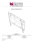
INSTALLATION INSTRUCTIONS
PSD-TL
60” / 72” / 84”
Floor Stand
NORTH AMERICA
3130 East Miraloma Avenue
Anaheim, CA 92806 USA
USA and Canada –
Phone: 800-368-9700
Fax: 800-832-4888
Other Locations – Phone: (001)-714-632-7100; Fax: (001)-714-632-1044
©Premier Mounts 2009
9532-565-001-03
EUROPE
Swallow House,
Shilton Industrial Estate,
Shilton, Coventry, England CV79JY
Phone: +44 (0) 2476 614700
Fax: +44 (0) 2476 614710
PSD-TL
Table of Contents
Warning Statements
Parts List
Installation Tools
Features
Support Pole Installation
Adapter Installation
CTM and PSM Series Installation
USA, UFA and RTM-L/S Installation
Optional Installations
Technical Specifications
Warranty
2
3
3
4
5
5
6
7
8
9
10
Warning Statements
PRIOR TO THE INSTALLATION OF THIS PRODUCT, THE INSTALLATION INSTRUCTIONS SHOULD BE READ AND
COMPLETELY UNDERSTOOD. THE INSTALLATION INSTRUCTIONS MUST BE READ TO PREVENT PERSONAL INJURY AND
PROPERTY DAMAGE. KEEP THESE INSTALLATION INSTRUCTIONS IN AN EASILY ACCESSIBLE LOCATION FOR FUTURE
REFERENCE.
PREMIER MOUNTS DOES NOT WARRANT AGAINST DAMAGE CAUSED BY THE USE OF ANY PREMIER MOUNTS
PRODUCT FOR PURPOSES OTHER THAN THOSE FOR WHICH IT WAS DESIGNED OR DAMAGE CAUSED BY UNAUTHORIZED
ATTACHMENTS OR MODIFICATIONS, AND IS NOT RESPONSIBLE FOR ANY DAMAGES, CLAIMS, DEMANDS, SUITS,
ACTIONS OR CAUSES OF ACTION OF WHATEVER KIND RESULTING FROM, ARISING OUT OF OR IN ANY MANNER
RELATING TO ANY SUCH USE, ATTACHMENTS OR MODIFICATIONS.
THE FLOOR STRUCTURE MUST BE CAPABLE OF SUPPORTING AT LEAST FIVE TIMES THE WEIGHT OF THE STAND AND
ALL ATTACHED DEVICES. IF NOT, THE FLOOR STRUCTURE MUST BE REINFORCED. THE MAXIMUM WEIGHT THAT
MAY BE USED WITH THIS STAND CANNOT EXCEED 160LBS. PROPER INSTALLATION PROCEDURE BY A QUALIFIED
SERVICE TECHNICIAN, AS OUTLINED IN THE INSTALLATION INSTRUCTIONS, MUST BE ADHERED TO. FAILURE TO
DO SO COULD RESULT IN SERIOUS PERSONAL INJURY, OR EVEN DEATH. THE OPTIONAL SHELF IS ONLY CAPABLE OF
HOLDING 25LBS. OR LESS.
SAFETY MEASURES MUST BE PRACTICED AT ALL TIMES DURING THE INSTALLATION OF THIS PRODUCT. USE PROPER
SAFETY GEAR AND TOOLS FOR THE INSTALLATION PROCEDURE TO PREVENT PERSONAL INJURY.
At least two qualified people should perform the assembly procedure. Injury and/or damage can result from dropping or mishandling the
flat-panel.
Do not install on a structure that is prone to vibration, movement or chance of impact. Failure to do so could result in damage to the flat-panel
and/or damage to the mounting surface.
This product is intended for indoor use only. Use of this product outdoors could lead to product failure and personal injury.
Do not install near sources of high heat. Do not install on a structure that is prone to vibration, movement or chance of impact.
This stand is intended for use only with the maximum weights indicated. Use with products heavier than the maximum weights
indicated may result in instability causing possible injury.
Contact Premier Mounts with any questions
(800) 368-9700
[email protected]
Page 2
Installation Instructions
PSD-TL
Parts List
Congratulations on the purchase of your new Premier Mounts PSD-TL stand. This stand is shipped with all proper
installation hardware and components. Make sure that none of these parts are missing and/or damaged before
beginning installation. If there are parts missing and/or damaged, please stop the installation and contact Premier Mounts
(800) 368-9700.
60”
72”
84”
The length will vary depending
on the application.
Support Poles (Qty 2)
PSD-TL Base (Qty 1)
PSD-SPA (Qty 1)
M8 x 10mm Set Screw (Qty 10)
M10 x 12mm Slotted
Hex Head (Qty 4)
M10 Flat Washers
(Qty 4)
Shelf (Optional)
NOTE:
The max weight capacity for
the shelf is 25lbs.
5/32” Allen Wrench
Installation Tools (not supplied)
Screwdriver
(Not Supplied)
Installation Instructions
1/2” Socket and Socket
Wrench (Not Supplied)
Page 3
PSD-TL
Features
Congratulations on the purchase of your new Premier Mounts PSD-TL Floor Stand. When combined with a mount, our floor stand
allows you to place a flat-panel in a horizontal or vertical position (with PSM and RTM-L/S mounts only). The flat-panel height
is adjustable to any point along the stand’s vertical support poles to achieve the perfect viewing level. The PSD-TL mates directly to
our CTM, USA, UFA, RTM-L/S or PSM series of mounts.
PSD-TL Base
PSD-TL Base
RTM-L Mount
RTM-S Mount
PSD-TL Base
PSD-TL Base
USA Mount
Page 4
UFA Mount
PSD-TL Base
CTM Series Mount
PSD-TL Base
PSM Series Mount
Installation Instructions
PSD-TL
Remove the stand out of the box and check for all proper hardware, if missing any hardware please call Premier Mounts.
A mount is required to complete the PSD-TL system. Refer to the mount’s installation instructions to install the mounting
bracket.
Please see Page 8 for optional shelf installation instructions.
Support Pole Installation
Adapter Installation
The PSD-SPA adapter is used with the CTM and
PSM Series mounts only. The PSD-SPA is not
needed when installing the USA, UFA or
RTM-L/S mounts.
The PSD-SPA must be facing forward when
mounted to the support poles.
2” Diameter Support Poles
PSD-SPA Adapter
(facing forward)
PSD-TL
M8 x 10mm
Set Screws
Mounting Columns
Allen Wrench
Mounting Screws
Allen Wrench
Step 1. Insert the poles inside the base columns of the
PSD-TL, making sure they are fully seated on
the base with the cable access holes facing the
rear of the base.
Step 2. Secure the support poles by inserting and
tightening the four (4) M8 x 10mm locking set
screws that are located on the back of the
mounting columns.
Step 3. Tighten set screw with the supplied Allen
wrench. Do not over tighten the screws.
Installation Instructions
Support Poles
Step 1. Install the PSD-SPA (mount adapter) over the top
of the support poles and secure it at the desired
height with the four (4) M8 x 10 set screws
(supplied).
Step 2. Use the Allen wrench (supplied) to secure the
adapter to the support poles.
Page 5
PSD-TL
CTM and PSM Series Installation
This stand is intended for use only with the maximum weights indicated. Use with products heavier than the
maximum weights indicated may result in instability causing possible injury.
The flat-panel is very heavy; two people are required to lift the flat-panel and secure it to the stand.
To install the mounting brackets to the flat-panel, refer to the CTM and PSM installation instructions.
Support Poles
PSD-SPA Adapter
Installing the CTM
The directional arrow must be pointing
up prior to installation. Secure the following plates to the secured PSD-SPA on the
support poles.
Step 1. For the CTM-Series, secure the back plate to
the four (4) threaded mounting points found on
the PSD-SPA with the four (4) M10 x 12 bolts
and flat washers (supplied).
Directional Arrow
CTM Back Plate
M10 Flat Washers
M10 x 12mm
Bolts
PSD-TL Base
(facing forward)
Step 2. Raise the flat-panel with the left and right brackets
secured to the flat-panel and insert the bottom and top hooks
from the mounting arms to the top and bottom rods found
on the CTM back plate.
Step 3. Secure the mounting arms with the two (2) M6 x 12mm
Safety knobs (supplied with the CTM mount).
Step 4. Insert and tighten two (2) M6 x 30mm lateral shift screws
(supplied with the CTM mount) on the bottom of the
mounting arms. These screws will prevent the flat panel
from moving side-to-side.
CTM Back
Plate
M6 x 12mm
Safety Knobs
CTM Series
Mounting Brackets
The safety knobs MUST be used. Failure to
do so may result in damage to the flat-panel or
personal injury.
Flat-Panel
M6 x 30mm Lateral
Shift Screws
PSD-TL Base
(facing forward)
Page 6
Installation Instructions
PSD-TL
Installing the PSM
Support Poles
Step 1. For the PSM-Series, secure the back plate to the four (4)
threaded mounting points found on the PSD-SPA with the
four (4) M10 x 12 bolts and flat washers (supplied).
Directional Arrow
PSD-SPA Adapter
PSM Back Plate
M10 Flat Washers
M10 x 12mm
Bolts
PSD-TL Base
(facing forward)
Step 2. Raise the flat-panel display with the mounting bracket
secured and insert the four (4) tab openings from the PSM
mount to the four (4) receiving tabs found on the back
plate.
Step 3. Push the flat-panel display down, right and down again to
lock the mount together.
Step 4. Make sure all tab openings are interlocked with the
receiving tabs before letting go of the flat-panel.
Step 5. Secure the brackets with two (2) M6 x 12mm Phillips
(supplied with the PSM mount) screws for additional
security.
PSM Back Plate
PSM
Mounting
Bracket
M6 x 12mm
Screws
Flat-Panel
PSD-TL Base
(facing forward)
USA, UFA and RTM-L/S Installations
The USA, UFA, RTM-L and RTM-S Series of stand/cart mounts attach to the PSD-TL without the use of the PSD-SPA.
Please follow the installation instructions that are packaged with these mounts.
Step 1. Slide the USA, UFA, RTM-L and RTM-S Series over and onto the support poles.
Step 2. Determine the desired height.
Step 3. Tighten the set screws, located at the rear of each mount, using the supplied Allen wrench.
Installation Instructions
Page 7
PSD-TL
Optional Installations
M8 x 10mm
Set Screws
Allen Wrench
Optional
Shelf
Suitable Hardware
(Commercially Available)
PSD-TL Base
(not facing forward)
Floor Installation
Step 1. If securing the base to the floor, use
(commercially available) hardware.
PSD-TL Base
(facing forward)
Shelf Installation
Do not install the optional shelf higher than
39”.
If using a shelf, please install prior to
attaching the flat-panel.
Step 1. The shelf must be attached before the flat-panel
and PSD-SPA adapter is installed to the
stand.
Step 2. Attach the shelf to the poles by sliding the shelf
over the poles and down into position.
Step 3. Determine the final height and secure the shelf
using four (4) M8 x 10mm set screws.
Step 4. Tighten these screws using the supplied Allen
wrench.
WARNING
DO NOT load the Stand past the maximum
weight capacity. Failure to comply with this
warning may result in Stand instability
leading to equipment damage or personal
injury.
Page 8
Installation Instructions
PSD-TL
Technical Specifications
All measurements are in inches(mm).
Installation Instructions
Page 9
PSD-TL
Warranty
PREMIER MOUNTS
LIMITED LIFETIME WARRANTY
What and Who is Covered by this Limited Warranty and for How Long
Premier Mounts warrants this product to be free from defects in material and workmanship for the lifetime of the
original owner of this product. The limited warranty is valid only for the original purchaser of the product.
What Premier Mounts Will Do
At the sole option of Premier Mounts, Premier Mounts will repair or replace any product or product part that is
defective. If Premier Mounts chooses to replace a defective product or part, a replacement product or part will be
shipped to you at no charge, but you must pay any labor costs.
What is Not Covered; Limitations
PREMIER MOUNTS DISCLAIMS ANY LIABILITY FOR DAMAGE TO MOUNTS, ADAPTERS,
DISPLAYS, PROJECTORS, OTHER PROPERTY, OR PERSONAL INJURY RESULTING, IN WHOLE OR
IN PART, FROM IMPROPER INSTALLATION, MODIFICATION, USE OR MISUSE OF ITS PRODUCTS.
PREMIER MOUNTS DISCLAIMS ALL OTHER WARRANTIES, EXPRESS OR IMPLIED, INCLUDING
WARRANTIES OF MERCHANTABILITY AND FITNESS FOR A PARTICULAR PURPOSE. PREMIER
MOUNTS IS NOT RESPONSIBLE FOR INCIDENTAL OR CONSEQUENTIAL DAMAGES, INCLUDING
BUT NOT LIMITED TO, INABILITY TO USE ITS PRODUCTS OR LABOR COSTS FOR REMOVING AND
REPLACING DEFECTIVE PRODUCTS OR PARTS. SOME STATES DO NOT ALLOW THE EXCLUSION
OR LIMITATION OF INCIDENTAL OR CONSEQUENTIAL DAMAGES, SO THE ABOVE LIMITATION
OR EXCLUSION MAY NOT APPLY TO YOU.
What Customers Must Do for Limited Warranty Service
If you discover a problem that you think may be covered by the warranty you MUST REPORT it in writing
to the address below within thirty (30) days. Proof of purchase (an original sales receipt) from the original
consumer purchaser must accompany all warranty claims. Warranty claims must also include a description of the
problem, the purchaser’s name, address, and telephone number. General inquiries can be addressed to Premier
Mounts Customer Service at 1-800-368-9700. Warranty claims will not be accepted over the phone or by fax.
Premier Mounts
Attn: Warranty Claim
3130 East Miraloma Ave.
Anaheim, CA 92806
How State Law Applies
THIS WARRANTY GIVES YOU SPECIFIC LEGAL RIGHTS, AND YOU MAY ALSO HAVE OTHER
RIGHTS WHICH VARY FROM STATE TO STATE.
Page 10
Installation Instructions