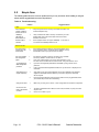
1
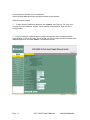
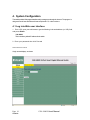
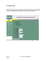
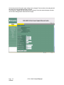
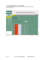
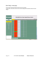
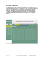
FriendlyNET GX6-2400W
®
24-Port Smart Gigabit Ethernet Switch
User’s Manual
FriendlyNET GX6-2400W 24-Port Smart Gigabit Ethernet Switch
User’s Manual
Asante
47709 Fremont Blvd Fremont, CA 94538 USA
SALES
408-435-8388
TECHNICAL SUPPORT
1.
408-435-4388: Worldwide
2.
www.asante.com/support
3.
[email protected]
Switch DEFAULTS
IP address: 192.168.0.1
Password: Asante
Copyright © 2008 Asante. All rights reserved. No part of this document,
or any associated artwork, product design, or design concept may be copied or reproduced in whole or in part by any means
without the express written consent of Asante. Asante and FriendlyNET are registered trademarks and the Asante logo,
AsanteCare, Auto-Uplink, IntraCare, and IntraAir are trademarks of Asante. All other brand names or product names are
trademarks or registered trademarks of their respective holders. All features and specifications are subject to change without
prior notice.
Rev D 1.16
Page 2
GX6-2400W User’s Manual
Asante
Table of Contents
1 Introduction…………………………………………………. 5
1.1 L2 managed switch………………………………………….. 5
1.2 Conventions used in this document………………… 5
1.2.1
Notations .............................................. 6
1.2.2
Typography........................................... 6
2 Getting to know the Smart Switch……………………….. 7
2..1 Package contents…………………………………..
7
2.2 Front Panel…………………………………………..
8
2.3 Rear Panel………………………………………...
9
2.4 Technical specifications……………………………
10
3 Quick start guide………………………………………..… 11
3.1 Part 1 — Installing the hardware…………………..
11
3.1.1
Installing the switch on a flat surface ....... 11
3.1.2
Mounting the switch on a rack ................. 11
3.2 Part 2 — Setting up the switch…………………….
11
3.2.1
Connect to the computers or a LAN........ 12
3.2.2
Attach the power adapter......................... 12
3.3 Part 3 — Basic switch setting for management….. 13
3.3.1
Setting up through the Web interface...... 13
3.4 Hardware reset
15
4 System Configuration …………………………………. 16
4.1 Login………………………………………………… 16
4.2 System Page…………………………………………. 17
4.3 Port Management................................................. 19
Page 3
4.3.1
Port Statistics………………………… 21
4.3.2
Detailed Statistics………………………. 22
4.3.3
LACP Statistics…………………………. 23
4.3.4
LACP Property………………………….. 24
GX6-2400W User’s Manual
Asante
4.3.5
4.4
4.5
Aggregation.................................................................. 25
VLAN Management......................................................26
Spanning Tree …………………………………..29
4.5.1
RSTP Port ........................................................ 30
4.6
4.6.1
4.7
4.7.2
4.7.3
4.8
4.8.1
4.8.2
4.8.3
Multicast IGMP Status..……………………………..31
IGMP Configuration……………………………….32
Security……………………………………………..33
802.1 x………………………………………………34
Storm Control…………………………………………35
Quality of Service……………………………………36
DSCP.. …………………………………..………..37
802.1 p………………….……………………………38
Rate Limit…………………………………………..39
4.9
Admin………………………………………………40
4.9.1
4.9.2
4.9.3
Port Mirroring…………………………..…………..40
Firmware Upgrade…………………………………..41
Reset………………………………………………..42
4.9.4
4.9.5
4.9.6
Factory default……………………………………..42
Save Configuration……………………………….43
Ping………………………………………………...44
4.10
Logout…………………………………...…………45
5
Troubleshooting………………………...…………46
5.1
Diagnosing problems using IP utilities……….….47
5.2
Simple fixes………………………………………...48
6
Glossary…………………………….……………..49
Appendix A: ……………………………………………………..54
A.1 FCC Compliance Statement………………….54
A.2 Important Safety Instructions …………..…….54
Page 4
GX6-2400W User’s Manual
Asante
1
Introduction
Congratulations on becoming the owner of the ASANTE smart switch! You may now manage your LAN
(local area network) through a friendly and powerful user interface.
This user guide tells you how to set up the smart switch, and how to customize its configuration to
get the most out of this product.
1.1
L2 smart managed features
● Energy Saving for Green Ethernet
● VLAN Tagging (IEEE 802.1Q)
● Source IP Filtering
● IEEE 802.1X with Radius Server
● Rapid Spanning Tree Protocol (RSTP) (IEEE 802.1w)
● Link Aggregation (IEEE 802.3ad)
● QoS (IEEE 802.1p/DSCP)
● Rate Limiting
● Storm Control (D LF/Multicast/Broadcast)
● Port Mirroring
● IGMP Snooping
● SNMP and Port statistics
● Flow Control (IEEE 802.3x)
● Web-based Management
Page 5
GX6-2400W User’s Manual
Asante
1.2 Conventions used in this document
1.2.1
Notations
• Acronyms are defined the first time they appear in text and in the glossary.
• For brevity, the smart switch is referred to as “the switch.”
• The terms LAN and network are used interchangeably to refer to a group of Ethernetconnected computers at one site.
1.2.2 Typography
• Italics are used to present the parameters for the command line interpreter.
• Boldface type text is used for items you select from menus and drop-down lists, and
text strings you type when prompted by the program.
Page 6
GX6-2400W User’s Manual
Asante
2
Getting to know the Smart Switch
2.1
Package contents
The switch package comes with the following items:
•
•
GX6-2400W (24-port) L2 smart managed switch
AC Power cord
•
•
Rack installation kit (two brackets with six screws)
Installation CD-ROM
Page 7
GX6-2400W User’s Manual
Asante
2.2
Front Panel
The front panel includes LED indicators that show the system and port status.
Front panel labels and LEDs
Label
POWER
Color
Green
Amber
Status
Unit is powered on
Flashing
Self-test, INIT, or downloading
On
Off
LINK/ACT
Green
Amber
Off
Page 8
Abnormal temperature or voltage
No power
On
Link (RJ-45 or SFP) is present; port is
enabled
Flashing
Data is being transmitted/received
On
1000Mbps
Off
1000Mbps
Description
On
No Ethernet link
100/10Mbps if LINK/ACT is on
GX6-2400W User’s Manual
Asante
2.3
Rear Panel
The switch rear panel contains the port for the power connection connections.
Power Connector
Figure 1. Rear panel Table 2. Rear panel
labels
No.
1
Page 9
Label
Power Connector
Description
Connects to the supplied power cord
GX6-2400W User’s Manual
Asante
2.4
Technical specifications
Standards
IEEE 802.3, 802.3u, 802.1Q, 802.1p, 802.3x,
802.1 D, 802.3ab, 802.3z, 802.3ac, TCP/IP
Port
24-Port 1000 BaseT with 2 shared Gigabit SFP
Speed
BaseT: 10/100/1000Mbps at full duplex,
20/200/2000Mbps at full duplex Gigabit
SFP: 2000Mbps at full duplex
Protocol
CSMA/CD
Cable Type
Category 5 or better
Max Segment Length
100M (328 ft) over Category 5 twisted-Pair cable
or better
LED
Power, LINK/ACT, 1000Mbps
Buffer Memory
500 KB
MAC Address
8K
Jumbo Frame
9 KB
Forwarding Architecture Store-and-forward
System Configuration
Web, SNMP
Size (W x D x H)
430 x 178 x 44 (mm), 16.9 x 7 x 1.7 (inch)
Weight (Net/Gross)
3.5 kg / 5.0 kg (105.8 oz / 141 oz)
Power
100 ~ 240 VAC, 50-60 Hz
EMI/EMC Certification
FCC A, CE
Operating Temp.
0°C to 40°C (32°F to 104°F )
Storage Temp.
Operating Humidity
Storage Humidity
-40°C to 70°C (-40°F to 158°F )
20% to 85%, relative humidity, non-condensing
20% to 90%, relative humidity, non-condensing
Page 10
GX6-2400W User’s Manual
Asante Networks
3
Quick start guide
This section provides the basic instructions to set up the switch environment. Part 1 shows you how to
install the switch on a flat surface or on a rack. Part 2 provides instructions to set up the hardware.
Part 3 shows you how to configure basic settings on the switch.
Obtain the following information from your network administrator before proceeding:
IP address for the switch
Default gateway for the network
Mask for this network
3.1
Part 1 — Installing the hardware
Connect the device to the power outlet, and your computer or network. Figure 5 illustrates the
hardware connections.
3.1.1 Installing the switch on a flat surface
The switch should be installed on a level surface that can support the weight of the switches and their
accessories. Attach four rubber pads on the marked location on the bottom of the switch.
3.1.2 Mounting the switch on a rack
Attach brackets to each side of the switch and make the posts insert to the switch.
Insert and tighten two screws to securely attach the bracket to the rack on each side.
3.2 Part 2 — Setting up the switch
Connect the device to the power outlet, and your computer or network.
Page 11
GX6-2400W User’s Manual
Asante Networks
3.2.1 Connect to the computers or a LAN
You can use Ethernet cable to connect computers directly to the switch ports. You can also connect
hubs/switches to the switch ports by Ethernet cables. You can use either the crossover or straight-through
Ethernet cable to connect computers, hubs, routers, or switches.
Use a twisted-pair Category 5 Ethernet cable to connect the
1000BASE-T port. Otherwise, the link speed can not reach
1Gbps.
3.2.2 Attach the power adapter
1. Connect the AC power cord to the POWER receptacle on the back of the switch and plug the
other end of the power cord into a wall outlet or a power strip.
2. Check the front LED indicators with the description in Table 4. If the LEDs light up as described,
the switch hardware is working properly.
No.
LED
Description
1
System
Solid green indicates that the device is turned
on. If this light is off, make sure that the power
cord is attached to the switch and plugged
into a power source.
2
LINK/ACT
Solid green indicates that the port can
communicate with the LAN, or flashing when
the device is sending or receiving data from
your LAN computer.
[1] to [24]
3
1 000Mbs
[1] to [24]
Page 12
Solid amber indicates that the port is
Communicating at 1000Mbps.
GX6-2400W User’s Manual
Asante Networks
Part 3 — Basic switch setting for management
After completing the hardware connections, configure the basic settings for your switch. You can only
apply basic settings using the Web interface.
Web interface: The switch has a set of pages to allow you to manage it using IE 6.0 or higher.
3.3.1 Setting up through the Web interface
To successfully connect your PC to the switch, your PC must have an IP address in the same range as the
switch. Perform the following steps to accomplish this .
1. To use the Web interface the first time, your computer must have its IP address set in the
192.168.0.xxx network. If you are unsure how to set the IP address, consult your OS
documentation.
2. With your PC connected to the switch, open
your Web browser (Internet Explorer), and type the following URL in the address/location box, and
press <Enter>:
192.168.0.1
This is the factory default I P address of the switch. A login screen appears, as
shown below.
Page 13
GX6-2400W User’s Manual
Asante Networks
Enter the password, and then click Proceed button.
Use the following default the first time log into this interface into this interface:
Default Password: Asante
3. To setup a new IP address or password, click “System”, (see Figure 3). Fill in the new
settings as New IP Address, network mask, gateway, and password. Then click Save
Settings button.
4. If your new address is different from the default, the browser can not update the switch
status window or retrieve any page. This is normal. You have to retype the new IP address in the
address/location box, and press <Enter>. The WEB link returns.
Page 14
GX6-2400W User’s Manual
Asante Networks
Part 4 - Hardware Reset
There is a recessed “reset” button on the right side of the front panel. The reset button may
be engaged by using a paper click or other small item. Id the reset button is momentarily
engaged, the switch performs a warm reset. If the reset button is engaged for 10 seconds or
longer, the switch performs a reset to factory default routine. Note: A reset to factory default
settings a IP addresses, passwords, etc. will all return to factory default settings
Page 15
GX6-2400W User’s Manual
Asante Networks
4. System Configuration
The switch provides Web pages that allow switch management through the Internet. The program is
designed to work best with Microsoft Internet Explorer® 5.5, or later versions.
4.1 Log into Web user interface
1. From a PC, open your web browser, type the following in the web address (or URL) field,
and press <Enter>:
1 92.168.0.1
This is the factory default IP address for the switch.
2. Enter your password then click Proceed
Default Password: Asante
A login screen displays, as shown
Page 16
Asante
GX6-2400W User’s Manual
4.2 System Page
The System Page allows you to view assorted system information. The MAC and IP address
information is found here. DHCP server information and version information is also here (see Figure 3).
The top section of the System Page is a display only. Changes can only be made below .
Page 17
Asante
GX6-2400W User’s Manual
On the lower portion of the system page, settings can be changed. The term refers to the setting that will
take effect once the Save Settings button is clicked.
This is where IP, SNMP and other settings can be changed. Once the desired changes are made,
click the Save Settings button at the bottom of the page.
Page 18
Asante
GX6-2400W User’s Manual
4.3 Port Management – Port Config
The following table shows the status and speed of each port. The speed and flow control
can be set for each port.
Page 19
GX6-2400W User’s Manual
Asante Networks
Port Config - Lower page
The port status and speed the high number ports can be viewed by
scrolling down. At the bottom of the screen, the Save Settings button should be clicked to save the
settings.
Page 20
GX6-2400W User’s Manual
Asante Networks
4.3.1 PORT STATISTICS
The statistics overview page is a per port byte count history. Every port has its own byte
counter for each of six categories. The categories are Tx Bytes, TX Frames, RX Bytes, RX
Frames, TX Errors and RX Errors. The chart that occupies the majority of this page is
output only. The clear and refresh buttons allow the related functions to be invoked.
Clicking the clear button allows information for all counters to be cleared back to zero.
Clicking the Refresh button increments all counters to include the most recent traffic
available.
Page 21
GX6-2400W User’s Manual
Asante Networks
4.3.2 Detailed Statistics
The detailed statistics page provides additional information on a per port basis. Here
the characteristics of the traffic being handled are categorized by byte size, error type
and various other parameters. Reset and clear buttons are available to be used on a per
port basis.
Page 22
GX6-2400W User’s Manual
Asante Networks
4.3.3 LACP Statistics
The displayed chart is a color coded output showing the LACP status of each port. A legend is
included to explain the meaning of various output colors and symbols. Below the legend there
is a refresh button that may be used to update the output chart for more current information.
Page 23
GX6-2400W User’s Manual
Asante Networks
4.3.4 LACP Property
All the ports in the link aggregation group MUST operate in full-duplex mode at the same speed. All ports
in the link aggregation group MUST be the same speed.
Page 24
GX6-2400W User’s Manual
Asante Networks
4.3.5 Aggregation
VLAN ports can be added to trunk groups on this page. Click Save Settings when done.
Page 25
GX6-2400W User’s Manual
Asante Networks
4.4 VLAN Management
The switch supports the creation of VLANs. Enter the VLAN ID for a new VLAN Then click add. A new
screen then presents itself.
Page 26
GX6-2400W User’s Manual
Asante Networks
VLAN - Setup
Page 27
GX6-2400W User’s Manual
Asante Networks
VLAN - Per Port Configuration
This screen is reached by clicking on the Port Config button on the VLAN page. The ports and trunks are
listed. Each one may be listed as a member or removed. Click Save Settings when finished.
Page 28
GX6-2400W User’s Manual
Asante Networks
4.5 Spanning Tree
RSTP
Page 29
GX6-2400W User’s Manual
Asante Networks
4.5.1 RSTP Port
Page 30
GX6-2400W User’s Manual
Asante
4.6 Multicast IGMP Status
This page shows the status of IGMP on a per VLAN basis. A refresh button is
available for use.
Page 31
GX6-2400W User’s Manual
Asante Networks
4.6.1 IGMP Configuration
Various IGMP settings can be enabled or disabled. Ports can also be
selected.
Page 32
GX6-2400W User’s Manual
Asante
4.7 Security – Source IP Filter
Selecting filter brings up the filter configuration settings. Filters may be applied on a per port
basis. Each port allows the ability to choose one of three settings, disabled, static or DHCP.
With static selected you may enter an IP address and subnet mask to specify a range of IP
addresses that are allowed to pass the switch. With DHCP selected , only the IP address
allocated by a DHCP server is allowed. No traffic from other IP addresses is allowed to pass
the switch.
Page 33
GX6-2400W User’s Manual
Asante Networks
4 . 7 . 2 802.1 x
This section is used for configuration of 802.1 x. Information is presented on a per port basis. Click
Save Settings near the bottom of the page when done.
Page 34
GX6-2400W User’s Manual
Asante
4 . 7 . 3 Storm Control
On the storm control configuration page five functions may be rate limited, ICMP rate, Learn
Frames rate, Broadcast Rate, Multicast Rate, and Flooded Unicast Rate. Each column has a
drop down menu with available rate selections. Once the settings are complete be sure to
click the Save Settings button to invoke the function. See Graphic.
Page 35
GX6-2400W User’s Manual
Asante Networks
4 . 8 Quality of Service
The GX6-2400W supports two types of QoS (Quality of Service.) The two options are
802.1p and DSCP. Use the QoS mode drop down menu to enable one of the QoS protocols.
There is no enable choice. Therefore, to enable QoS, do so by selecting either 802.1p or
DSCP. Each selection brings up its own configuration chart.
With 802.1p selected you have the ability to prioritize traffic based on the 802.1p value. Once
the settings are complete be sure to click the Save Settings button to invoke the function. See
Graphic.
Page 36
GX6-2400W User’s Manual
Asante
4.8.1 DSCP
With DSCP selected you have the ability to prioritize traffic based on the DSCP value. The
GX6-2400W supports four levels of priority. Once the settings are complete be sure to click the
Save Settings button to invoke the function. See Graphic.
Page 37
GX6-2400W User’s Manual
Asante Networks
4.8.2 - 802.1p
Page 38
GX6-2400W User’s Manual
Asante
4.8.3 Rate limit
The rate limit configuration page allows the ability to allocate bandwidth on a per port
basis. Both policer and shaper allow limits to be set.
Page 39
GX6-2400W User’s Manual
Asante Networks
4.9 Admin
4.9.1
Port Mirroring
Any port can be the source for a mirror operation. In the “Mirror Source” column there is a box
corresponding to each specific port number. When a box is clicked, a check mark appears. This
enables that port to be the source. Near the bottom of the page on the “Mirror Port” row use the
selector to designate the mirror port. This is the port the sourced information will be mirrored
to.
Once the settings are complete be sure to click the Save Settings button to invoke the
function.
Page 40
GX6-2400W User’s Manual
Asante
4.9.2 Firmware Upgrade
The software update page allows the firmware to be updated for the switch. To use this
function the software must exist in some location that may be easily browsed. Either
enter the exact path manually via the keyboard, or use the browse button to browse for
its location. Once the firmware file location is identified, click the upload button.
Page 41
GX6-2400W User’s Manual
Asante Networks
4.9.3 Reboot
This allows the switch to be rebooted (reset). To reset click yes. After clicking yes, the system
reboots and therefore will be unavailable for several seconds. Login will be required.
4.9.4 Factory default
This resets all settings back to factory default. If the yes button is clicked, all
configurations like passwords, vlans, etc. except IP configurations (address, subnet mask, and
default gateway) will all return to factory default settings. The IP configurations can be reset
back to factory defaults by pushing the reset button in the front panel. As a safety measure, click
on the system button and record the current settings before resetting the switch to default.
Some of the settings may need to be reentered once the switch reboots.
Page 42
GX6-2400W User’s Manual
Asante
4.9.5 Save Configurations
The save configuration function can be used to save the switch configuration file. To save the
configuration click the backup button and save it to an easily located location. On this page
an existing configuration from the same switch or another similar switch may be
downloaded. To do this the complete file name may be entered manually via keyboard, or the
file may be located using the browse button. Once the file is identified click the upgrade
button to execute the download.
Page 43
GX6-2400W User’s Manual
Asante Networks
4.9.6 Ping Function
This page contains fields for IP Address, iteration count, and timeout. A refresh button is also
available.
You can also test whether access to the Internet is working by typing an external address, such as that
for www.yahoo.com (216.115.108.243). If you do not know the IP address of a particular Internet location,
you can use the nslookup command, as explained in a later section.
From most other I P-enabled operating systems, you can execute the same
command at a command prompt or through a system administration utility.
Page 44
GX6-2400W User’s Manual
Asante
4.10 Logout
Selecting Logout ends the session. The login screen is again presented as shown below.
Page 45
GX6-2400W User’s Manual
Asante Networks
5. Troubleshooting
Problems with suggestion actions is also provided.
All the known bugs are listed in the release note. Read the release note before you set up the
switch. Contact Customer Support if these suggestions do not resolve the problem.
5.1 Diagnosing problems using IP utilities
5.1.1 ping
Ping is a command you can use to check whether your PC can recognize other computers on your
network and the Internet. A ping command sends a message to the computer you specify. If the computer
receives the message, it sends messages in reply. To use it, you must know the IP address of the
computer with which you are trying to communicate.
On Windows-based computers, you can execute a ping command from the Start menu. Click the Start
button, and then click Run. In the Open text box, type a statement such as the following:
ping 192.168.1.1
You can substitute any private IP address on your LAN or a public IP address for an Internet site, if known.
If the target computer receives the message, a Command Prompt window appears as shown.
Using the ping utility
If the target computer cannot be located, you will receive the message “Request timed out.”
Using the ping command, you can test whether the path to the switch is working (using the preconfigured default LAN IP address 192.168.1.1) or another address you assigned.
You can also test whether access to the Internet is working by typing an external address, such as that
for www.yahoo.com (216.115.108.243). If you do not know the IP address of a particular Internet location,
you can use the nslookup command, as explained in the following section.
From most other IP-enabled operating systems, you can execute the same command at a command
prompt or through a system administration utility.
Page 46
GX6-2400W User’s Manual
Asante
5.1.2 nslookup
You can use the nslookup command to determine the I P address associated with an Internet site name.
You specify the common name, and the nslookup command looks up the name on your DNS server
(usually located with your ISP). If that name is not an entry in your ISP’s DNS table, the request is then
referred to another higher-level server, and so on, until the entry is found. The server then returns the
associated I P address.
On Windows-based computers, you can execute the nslookup command from the Start menu. Click the
Start button, then click Run. In the Open text box, type the following:
nslookup
A Command Prompt window displays with a bracket prompt
(>). At the prompt, type the name of the Internet address you are interested in, such as
www.absnews.com.
The window displays the associate IP address, if known. See Figure 29.
Figure 29. Using the nslookup utility
There may be several addresses associated with an Internet name. This is common for web sites that
receive heavy traffic; they use multiple, redundant servers to carry the same information.
To exit from the nslookup utility, type exit and press <Enter> at the command prompt.
Page 47
GX6-2400W User’s Manual
Asante Networks
5.2
Simple fixes
The following table lists some common problems that you may encounter when installing or using the
switch, and the suggested actions to solve the problems.
Table 6. Troubleshooting
Problem
Suggested Action
LEDs
Power LED does
not light up after the
switch is turned on.
1000Mbps
LED does not
illuminate after an
Ethernet cable is
attached
1.
1.
Verify if the power cord is securely connected to the switch and
a wall socket/power strip.
Verify if the Ethernet cable is securely connected to your LAN
switch/hub/PC and to the switch. Make sure the PC and/or
hub/switch is turned on.
2.
Some equipment does not support 1000Mbps. In this case, it
Is normal for the !000Mbps LED to be out.
PC cannot access
another host in the
same network
1.
2.
Check that the Ethernet cabling is good and the LED is green.
If the port LED is amber, check if this port is disabled. You may
need to wait a minute if you just turned on the switch.
PCs cannot display
web configuration
pages.
1.
The switch is powered up and the connecting port is enabled.
The factory default IP for the switch is 192.168.1.1.
Verify your network setup in your PC for this information. If your
PC does not have a valid route to access the switch, change the switch IP to an
You forgot/lost your
WEB Configuration
password.
1.
If you have not changed the password from the default, try using “Asante” as the
password.
2.
Login to console mode through RS232 or USB, use “sys user show” to display the lost
information
Some pages do not
display completely
1
Verify that you are using Internet Explorer v5.5 or later. Netscape is not supported.
Support for Javascript® must be enabled in your browser. Support for Java® may
also be required.
2
Ping the switch IP address to see if the link is stable. If some ping packets fail, check
your network setup to make sure a valid setting.
Changes not saved
1.
Make sure you have gone to Admin – Save configuration and saved the configuration.
Cannot show the
texts on the terminal
emulator.
1.
The factory default baud rate is 9600, no flow control, 8 bit data, no parity check and
stop bit is one.
2.
Check if the cable is good.
Network Access
Page 48
2.
GX6-2400W User’s Manual
Asante Networks
6
Glossary
1 0BASE-T
A designation for the type of wiring used by Ethernet networks
with a data rate of 10 Mbps. Also known as Category 3 (CAT 3) wiring. See also data rate,
Ethernet.
1 00BASE-T
A designation for the type of wiring used by Ethernet networks
with a data rate of 100 Mbps. Also known as Category 5 (CAT 5) wiring. See also data rate,
Ethernet.
1 000BASE-T
A designation for the type of wiring used by Ethernet networks
with a data rate of 1000 Mbps.
binary
The "base two" system of numbers, that uses only two digits, 0
and 1, to represent all numbers. In binary, the number 1 is written as 1, 2 as 10, 3 as 11, 4 as
100, etc. Although expressed as decimal numbers for convenience, IP addresses in actual
use are binary numbers; e.g., the IP address 209.191.4.240 is
11010001.10111111.00000100.11110000 in binary. See also bit, IP address, network mask.
bit
Short for "binary digit," a bit is a number that can have two values,
0 or 1. See also binary.
bps
bits per second
CoS
Class of Service. Defined in 802.1Q, the value range is from 0 to 7. Due to 4 internal
traffic class mapping to 8 priority, Only Cos value 0,2,5,7 are valid according to Cos
Queue Mapping.
broadcast
To send data to all computers on a network.
download
To transfer data in the downstream direction, i.e., from the
Internet to the user.
Ethernet
The most commonly installed computer network technology,
usually using twisted pair wiring. Ethernet data rates are 10 Mbps and 100 Mbps. See also
10BASE-T, 100BASE-T, twisted pair.
filtering
To screen out selected types of data, based on filtering rules.
Filtering can be applied in one direction (ingress or egress), or in both directions.
Page 49
GX6-2400W User’s Manual
Asante Networks
filtering rule A rule that specifies what kinds of data the a routing device will
accept and/or reject. Filtering rules are defined to operate on an interface (or multiple interfaces) and in a particular
direction (upstream, downstream, or both).
FTP
File Transfer Protocol
A program used to transfer files between computers connected to the Internet. Common uses include uploading new
or updated files to a web server, and downloading files from a web server.
host
HTTP
A device (usually a computer) connected to a network.
Hyper-Text Transfer Protocol
HTTP is the main protocol used to transfer data from web sites so that it can be displayed by web browsers. See
also web browser, web site.
ICMP
Internet Control Message Protocol
An Internet protocol used to report errors and other network-related information. The ping command makes use of
ICMP.
Internet
The global collection of interconnected networks used for both
private and business communications.
intranet
A private, company-internal network that looks like part of the
Internet (users access information using web browsers), but is accessible only by employees.
IP
See TCP/IP.
IP address
Internet Protocol address
The address of a host (computer) on the Internet, consisting of four numbers, each from 0 to 255, separated by
periods, e.g., 209.191.4.240. An IP address consists of a network ID that identifies the particular network the host
belongs to, and a host ID uniquely identifying the host itself on that network. A network mask is used to define the
network ID and the host ID. Because IP addresses are difficult to remember, they usually have an associated domain
name that can be specified instead. See also domain name, network mask.
ISP
Internet Service Provider
A company that provides Internet access to its customers, usually for a fee.
LAN
Local Area Network
A network limited to a small geographic area, such as a home, office, or small building.
LED
Light Emitting Diode
An electronic light-emitting device. The indicator lights on the front of the SL-1 000 are LEDs.
Page 50
50
GX5-2400W User’s Manual
Asante Technologies Inc
MAC address
Media Access Control address
The permanent hardware address of a device, assigned by its manufacturer. MAC addresses are
expressed as six pairs of characters.
mask
See network mask.
Multicast
To send data to a group of network devices.
Mbps
Abbreviation for Megabits per second, or one million bits per
second. Network data rates are often expressed in Mbps.
Monitor
Also called “Roving Analysis”, allow you to attach a network
analyzer to one port and use it to monitor the traffics of other ports on the switch.
network
A group of computers that are connected together, allowing them
to communicate with each other and share resources, such as software, files, etc. A network can
be small, such as a LAN, or very large, such as the Internet.
network mask
A network mask is a sequence of bits applied to an IP address to
select the network ID while ignoring the host ID. Bits set to 1 mean "select this bit" while bits set to
0 mean "ignore this bit." For example, if the network mask 255.255.255.0 is applied to the IP
address 100.10.50.1, the network ID is 100.10.50, and the host ID is 1. See also binary, IP
address, subnet, "IP Addresses Explained" section.
NIC
Network Interface Card
An adapter card that plugs into your computer and provides the physical interface to your network
cabling, which for Ethernet NICs is typically an RJ-45 connector. See Ethernet, RJ-45.
packet
Data transmitted on a network consists of units called packets.
Each packet contains a payload (the data), plus overhead information such as where it came
from (source address) and where it should go (destination address).
ping
Packet Internet (or Inter-Network) Groper
A program used to verify whether the host associated with an IP address is online. It can also be used to reveal the IP
address for a given domain name.
port
A physical access point to a device such as a computer or router,
through which data flows into and out of the device.
protocol
A set of rules governing the transmission of data. In order for a
data transmission to work, both ends of the connection have to follow the rules of the protocol.
Page 51
GX6-2400W User’s Manual
Asante Networks
remote
In a physically separate location. For example, an employee
away on travel who logs in to the company’s intranet is a remote user.
Registered Jack Standard-45
RJ-45
The 8-pin plug used in transmitting data over phone lines. Ethernet cabling usually uses this type of connector.
routing
Forwarding data between your network and the Internet on the
most efficient route, based on the data’s destination IP address and current network conditions. A device that performs
routing is called a router.
A subnet is a portion of a network. The subnet is distinguished
subnet
from the larger network by a subnet mask which selects some of the computers of the network and excludes all
others. The subnet's computers remain physically connected to the rest of the parent network, but they are treated as
though they were on a separate network. See also network mask.
subnet mask
A mask that defines a subnet. See also network mask.
See TCP/IP.
TCP
Transmission Control Protocol/Internet Protocol
TCP/IP
The basic protocols used on the Internet. TCP is responsible for dividing data up into packets for delivery and
reassembling them at the destination, while IP is responsible for delivering the packets from source to
destination. When TCP and IP are bundled with higher-level applications such as HTTP, FTP, Telnet, etc.,
TCP/IP refers to this whole suite of protocols.
An interactive, character-based program used to access a
Telnet
remote computer. While HTTP (the web protocol) and FTP only allow you to download files from a remote computer,
Telnet / allows you to log into and use a computer from a remote location.
Trivial File Transfer Protocol
TFTP
A protocol for file transfers, TFTP is easier to use than File Transfer Protocol (FTP) but not as capable or secure.
Trunk
Two or more ports are combined as one virtual port, also called
as Link Aggregation.
TTL
Time To Live
A field in an IP packet that limits the life span of that packet. Originally meant as a time duration, the TTL is usually
represented instead as a maximum hop count; each router that receives a packet decrements this field by one. When the
TTL reaches zero, the packet is discarded.
twisted pair
Page 52
52
The ordinary copper telephone wiring long used by telephone
GX5-2400W User’s Manual
Asante Technologies Inc
companies. It contains one or more wire pairs twisted together to reduce inductance and noise.
Each telephone line uses one pair. In homes, it is most often installed with two pairs. For
Ethernet LANs, a higher grade called Category 3 (CAT 3) is used for 10BASE-T networks,
and an even higher grade called Category 5 (CAT 5) is used for 100BASE-T networks. See also
10BASE-T, 100BASE-T, Ethernet.
Upstream
The direction of data transmission from the user to the Internet.
VLAN
Virtual Local Area Network
WAN
Wide Area Network
Any network spread over a large geographical area, such as a country or continent. With
respect to the SL-1000, WAN refers to the Internet.
Web browser
A software program that uses Hyper-Text Transfer Protocol
(HTTP) to download information from (and upload to) web sites, and displays the information,
which may consist of text, graphic images, audio, or video, to the user. Web browsers use
Hyper-Text Transfer Protocol (HTTP). Popular web browsers include Netscape Navigator and
Microsoft Internet Explorer. See also HTTP, web site, WWW.
Web page
A web site file typically containing text, graphics and hyperlinks
(cross-references) to the other pages on that web site, as well as to pages on other web sites.
When a user accesses a web site, the first page that is displayed is called the home page. See
also hyperlink, web site.
Web site
A computer on the Internet that distributes information to (and
gets information from) remote users through web browsers. A web site typically consists of
web pages that contain text, graphics, and hyperlinks. See also hyperlink, web page.
WWW
World Wide Web
Also called (the) Web. Collective term for all web sites anywhere in the world that can be
accessed via the Internet
Page 53
GX6-2400W User’s Manual
Asante Networks
Appendix A
A.1 FCC Compliance Statement
This equipment has been tested and found to comply with the limits for a Class A digital device, pursuant
to part 15 of the FCC Rules. These limits are designed to provide reasonable protection against harmful
interference when the equipment is operated in a commercial environment. This equipment generates,
uses, and can radiate radio frequency energy and, if not installed and used in accordance with
the instruction manual, may cause harmful interference to radio communications. Operation of this
equipment in a residential area is likely to cause harmful interference, in which case you will be
required to correct the interference at your own expense.
A.2 Important Safety Instructions
Caution: Do not use an RJ-11 (telephone) cable to connect network equipment.
1.
Read all of these instructions.
2.
Save these instructions for later use.
3.
Follow all warnings and instructions marked on the product.
4.
Unplug this product from the wall outlet before cleaning. Do not use liquid cleaners or
aerosol cleaners. Use a damp cloth for cleaning.
5.
6.
Do not use this product near water.
Do not place this product on an unstable cart or stand. The product may fall, causing serious
damage to the product.
7.
The air vent should never be blocked (such as by placing the product on a bed, sofa or
rug). This product should never be placed near or over a radiator or heat register. This product should
not be placed in a built-in installation unless proper ventilation is provided.
8.
This product should be operated from the type of power source indicated on the marking
label. If you are not sure of the type of power available, consult your dealer or local power company.
9.
This product is equipped with a three-wire grounding type plug, which is a plug having a
third (grounding) pin. This plug will only fit into a grounding type power outlet. This is a safety feature. If
you are unable to insert the plug into the outlet, contact your electrician to replace your outlet. Do not
defeat the purpose of the grounding type plug.
Page 54
54
GX5-2400W User’s Manual
Asante Technologies Inc
10. Do not allow anything to rest on the power cord. Do not place this product where people will walk
on the cord.
11. If an extension cord is used with this product, make sure that the total ampere ratings on the
products into the extension cord do not exceed the extension cord ampere rating. Also make
sure that the total of all products plugged into the wall outlet does not exceed 15 amperes.
12. Never push objects of any kind into this product through air ventilation slots as they may touch
dangerous voltage points or short out parts that could result in a risk of fire or electric shock. Never
spill liquid of any kind on the product.
13. Do not attempt to service this product yourself, as opening or removing covers may expose you
to dangerous voltage points or other risks. Refer all servicing to service personnel.
Page 55
GX6-2400W User’s Manual
Asante Networks