1
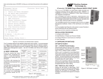
Once connected, press <ENTER> to bring up a command line prompt on the attached
PC.
Management Options iConverter, Serial Agent
Network Management
1: Chassis and Module Management
2: Set Module Name Preferences
Management Module Preferences
3: IP and Control Preferences
4: SNMP Preferences
5: Abandon Preference Changes
6: Save Preference Changes
7: Restore Factory Defaults
8: Restart Management Module
9: Other Networking Features
Installation Procedure
1) Configure DIP-Switches
2) Install Module in Chassis and Connect Cables
3) Configure Module via Command Line Interface
4) Verify Operation
IP Address = 192.168.1.220
Chassis Number = 1
Enter Choice, <H>elp, E<x>it >
1) CONFIGURE DIP-Switches
Figure E: Command Line Interface Menu Options
The CLI interface allows for the detailed configuration of the module. It is recommended
to configure the module with an IP address associated with the attached network.
Also, SNMP traphost address should be configured if the module is managed with an
SNMP-based Management System. LED Function
Color
Off State
On / Blinking State
“Legend”
See the GX/TM2 User Manual for
Power
“Pwr”
Green
No
power
On:
Module
has power
complete information.
Once the module has been installed
and configured per steps 1 - 3, verify
the module is operational by viewing
the LED indicators.
The Power LED indicates the module
is receiving power from the chassis.
The Fiber Optic link LED indicates
the fiber optic connection has been
established.
The UTP link LED indicates the
module has established a connection
across its UTP port.
Form 040-8920N-002 C
9/10
The iConverter® GX/TM2 Plug-In media converter and Network
Interface Device (NID) provides 10BASE-T ,100BASE-TX or
1000BASE-T UTP to 1000BASE-X fiber media conversion.
The GX/TM2 has built-in Operation, Administration and Maintenance
(OAM) functionality enabling the GX/TM2 to operate as a managed
demarcation point at the customer premises and network edge,
offering Quality of Service capabilities.
The GX/TM2 module can be managed using NetOutlook® SNMP
Management Software, third-party SNMP Client, Telnet or the
Command Line Interface (CLI).
For the complete User Manual on this product, access Omnitron’s
secure download site and request access.
http://www.omnitron-systems.com/login.php
Management Module Maintenance
10: Firmware Update
11: Set Date/Time
4) Verify Operation
iConverter GX/TM2 Plug-in Module QUICK START GUIDE
On: Power available from
installed Power Supply # X
Blinking: No power available from
installed Power Supply # X
Power Supply
Status # X
Green
Chassis Power
Supply not
installed
1000Mbps
Fiber Optics
“FO”
Green
No Fiber Link
Chassis
Management
Master/Slave
“Msr/Slv”
Green
Chassis in Slave
Mode
On: Chassis Master Mode
Blinking: Operating in OAM Mode
UTP port
100Mbps
“100”
Green
Not linked at
100Mbps
On: UTP linked at 100Mbps
Blinking: UTP Data Activity
UTP port
1000Mbps
“1000”
Green
Not linked at
1000Mbps
On: UTP linked at 1000Mbps
Blinking: UTP Data Activity
UTP port
10Mbps
“100 + 1000”
Green
Not linked at
10Mbps
On: UTP linked at 10Mbps
Blinking: UTP Data Activity
UTP port
Full-Duplex
“FDX”
Green
Half-Duplex
when any UTP
link is active
On: Fll-Duplex when any UTP
link is active
On: Fiber Link
Blinking: Fiber Data Activity
DIP-Switch Bank 1
SW1 - Fiber Auto/Manual Negotiation “AN/Man”
When this DIP-switch is in the LEFT “AN”
position (factory default), the fiber optic
port automatically determines the duplex
and pause modes of the connecting fiber
optic device. If the connecting fiber optic
device cannot provide the proper signal
to indicate its own mode of operation, the
DIP-switch should be set to the RIGHT fiber
optic “Man” position. When Port 1 is set to
1000X manual mode, no capabilities are
advertised.
NOTE: The fiber optic port of the GX/TM2
is always in Full-Duplex mode.
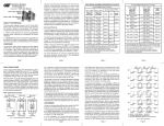
Figure A: DIP-switch Locations
SW2, SW3, SW4 and SW5 - UTP Control
DIP-switches SW2, SW3, SW4 and SW5 control the setting of the UTP port. See Figure
C for the UTP Configuration matrix.
NOTE: Refer to the table in Section 3.2.1.2 of the GX/TM2 User Manual for the
more detailed information.
Figure F: LED Indicators
Omnitron Systems Technology * 140 Technology Dr.* #500 * Irvine, CA 92618
949.250.6510 tel * 949.250.6514 fax * www.omnitron-systems.com
Page 1
Switch
Left
(Factory Default)
Right
SW6
SW1
AN:
Fiber Auto-Negotiation
Man:
Fiber Manual Negotiation
SW2
AN:
UTP Auto-Negotiation
Man:
UTP Manual
SW3
1000:
UTP 1000Mbps
10-100:
UTP 10-100Mbps
SW4
100:
UTP 100Mbps
10:
UTP 10Mbps
SW5
FDX:
UTP Full-Duplex
HDX:
UTP Half-Duplex
SW7
SW8
Left
Left
Left
Link Segment (LS)
(Factory Default)
Right
Left
Left
Link Propagate (LP)
Left
Right
Left
Remote Fault Detect + Link
Segment (RFD + LS)
Right
Right
Left
Remote Fault Detect + Link
Propagate (RFD + LP)
Left
Left
Right
Symmetrical Fault Detect (SFD)
Right
Left
Right
Asymmetrical Link Propagate
Port 1 to Port 2 (ALP P1-P2)
Left
Right
Right
Asymmetrical Link Propagate
Port 2 to Port 1 (ALP P2-P1)
Right
Right
Right
Pass Remote Link Fault (PRLF)
SW6
SW7
See Link Mode Selection
SW8
Link Mode Selection
Figure B: DIP-Switch Bank 1
SW2
SW3
SW4
SW5
Function
AN
1000
100 or 10
FDX
The UTP port is set to auto-negotiation with the following modes advertised:
1000F, 1000H, 100F, 100H, 10F, 10H
AN
1000
100 or 10
HDX
The UTP port is set to auto-negotiation with the following modes advertised:
1000H, 100F, 100H, 10F, 10H
AN
10-100
100
FDX
The UTP port is set to auto-negotiation with the following modes advertised:
100F, 100H, 10F, 10H
AN
10-100
100
HDX
The UTP port is set to auto-negotiation with the following modes advertised:
100H, 10F, 10H
AN
10-100
10
FDX
The UTP port is set to auto-negotiation with the following modes advertised:
10F, 10H
AN
10-100
10
HDX
The UTP port is set to auto-negotiation with the following modes advertised:
10H
MAN
1000
100 or 10
FDX
The UTP port is set to auto-negotiation with the following modes advertised:
1000F, 1000H, 100F, 100H, 10F, 10H
MAN
1000
100 or 10
HDX
The UTP port is set to auto-negotiation with the following modes advertised:
1000H, 100F, 100H, 10F, 10H
MAN
10-100
100
FDX
The UTP port is set to manual negotiation and is forced to:
100F
MAN
10-100
100
HDX
The UTP port is set to manual negotiation and is forced to:
100H
MAN
10-100
10
FDX
The UTP port is set to manual negotiation and is forced to:
10F
MAN
10-100
10
HDX
The UTP port is set to manual negotiation and is forced to:
10H
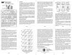
Figure C: UTP Configuration Matrix
Port of the GX/TM2 is isolated from the
chassis’ Ethernet Backplane. When this
DIP-switch is in the RIGHT “EN” position,
the Backplane Port is enabled. This
allows Ethernet Backplane connectivity
to an adjacent module via the chassis
Backplane Link “A” or “B” depending on
the switch setting.
Switch
Left (Factory Default)
Right
SW1
A-DS: Port A Disabled
A-EN: Port A Enabled
SW2
B-DS: Port B Disabled
B-EN: Port B Enabled
SW3
M/SL:
Master/Slave Auto-Select
SL:
Slave-Mode Only
SW4
Reserved
Reserved
Figure D: DIP-Switch Bank 2
SW3 - master/slave
When the GX/TM2 module is installed in a chassis with an iConverter management
module such as a 10/100M2, set the DIP-switch to the LEFT “M/SL” position (factory
default), the assignment of mastership is automatically negotiated by the installed
management modules. To designate the GX/TM2 module as the master of the chassis,
set the DIP-switch on the module to the LEFT “M/SL” position, and set the DIP-switch
on the other installed management modules to the RIGHT “SL” position to enable
Slave-Only mode.
SW4 - Reserved
This DIP-switch is for factory use only and must always remain in the LEFT position
(factory default).
2) Install Module in Chassis and Connect Cables
a. Carefully slide the module into an open slot in the chassis. Align the module with
the installation guides and ensure that the module is firmly seated against the
backplane. Secure the module by fastening the front panel thumbscrew (push in and
turn clockwise to tighten) to the chassis front. Verify the “Pwr” LED is ON (indicating
the chassis is powered).
b. When using a GX/TM2 SFP model (8939N-0), insert the SFP Fiber transceiver into
the Port 1 SFP receptacle on the GX/TM2.
NOTE: The release latch of the SFP Fiber transceiver must be in the closed
position before insertion.
c. Connect an appropriate multimode or single-mode fiber cable to the fiber port of the
installed module. It is important to ensure that the transmit (Tx) is attached to the
receive side of the device at the other end and the receive (Rx) is attached to the
transmit side. Single-fiber (SF) media converter models operate in pairs. The Tx
wavelength must match the Rx wavelength at the other end and the Rx wavelength
must match the Tx wavelength at the other end
d. Connect the UTP port via a Category 5 cable to a 10BASE-T, 100BASE-TX or
1000BASE-T Ethernet device.
3) Configure Module via Command Line Interface
SW1, SW2 - bACkplane enable
When the DIP-switch is in the LEFT “DS” position (factory default), the Backplane
To access the Command Line Interface (CLI), connect the GX/TM2 RS-232 Console
Port to the COM port of a computer equipped with terminal emulation software such
as HyperTerminal. The Console Port (DCE) is a mini DIN-6 female connector which
can be changed to a DB-9 connector with the included adapter. The GX/TM2 Console
Port is a standard asynchronous serial interface.
Start HyperTerminal and select the correct COM Port in the HyperTerminal “Connect
To:” window. Set the serial port to the following:
Bits Per Second 57,600
Parity
NONE
Stop Bits 1
Hardware Flow Control NONE
Data Bits 8
Page 2
Page 3
SW6, SW7, SW8 - Link Modes
These three DIP-switches configure the link mode settings. It is recommended to have
link modes DOWN (default) during the initial installation. After the circuit has been tested
and operational, configure the module for the desire mode. For detailed information on
the operation of the different Link Modes, download the application note “iConverter
Link Modes” available on Omnitron’s web site.
DIP-SWITCH BANK 2