1
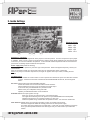
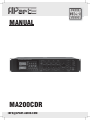
MANUAL
MA200CDR
[email protected]
Safety First!
• Read all documentation before operating your equipment.
• Retain all documentation for future reference.
• Save the carton and packing material even if the equipment has arrived in good condition.
Should you ever need to ship the unit, use only the original factory packing.
• Do not spill water or other liquids into or on the unit.
• Make sure power outlets conform to the power requirements listed on the back of the unit.
• Do not use the unit if the electrical power cord is frayed or broken.
• Always operate the unit with the AC ground wire connected to the electrical system ground.
• Have gain controls on amplifiers turned down during power-up to prevent
speaker damage if there are high signal levels at the inputs.
• Do not connect the inputs / outputs of amplifiers or consoles to any other voltage source, such
as a battery, mains source, or power supply, regardless of whether the amplifier or console is
turned on or off.
• Power down & disconnect units from mains voltage before making connections.
• Do not use the unit near stoves, heat registers, radiators, or other heat producing devices.
• Do not block fan intake or exhaust ports. Do not operate equipment on a surface or in an
environment which may distort the normal flow of air around the unit. If the unit is used in an
Extremely dusty or smoky environment, the unit should be periodically “blown free” of dust.
• Do not remove the cover. Removing the cover will expose you to potentially dangerous voltages.
• Do not drive the inputs with a signal level greater than that required to drive equipment to full
output.
• Do not run the output of any amplifier back into another input.
• Do not ground the red output terminal, never connect a red output terminal to another red
output terminal.
• In case of mal-function this device should be serviced by qualified service personnel only.
WWW.APART-AUDIO.COM
Content
1. APart MA200CDR Mixing Amplifier
2. Front Panel
3. Rear Panel
4.Tuner Controls
5. Inside Settings
6. Overview Of The MA200 Series
7. How To Deal With 100V Loudspeakers Systems
8. Technical Specifications
9. Block Diagram
[email protected]
1. APart MA200CDR Mixing Amplifier
The MA200CDR is a professional 4 zone PA mixing amplifier for commercial and industrial applications.
Rarely seen on its competitors, all microphone inputs have integrated speech filters and they are
high-class transistor-balanced type, allowing good control of hum and noise over long cables.
He’s able to drive 8-ohm or constant-voltage loudspeaker lines (50-70-100V).
The amplifier has integrated radio, 4 microphone inputs, 4 selectable line sources and
one emergency/telephone input.
Mic input 1 is meant to be the main microphone paging input, for its signal can be fed via the
front ¼” TRS phone jack or via a combo XLR3/jack or DIN 5 or euroblock connector at the back.
The MA200CDR has a three level priority system.
The emergency/telephone input at the back has the highest priority. Its signal goes directly to the
main amplifier, bypassing any front control, and an attenuator next to the input sets its level. Microphone input 1 has the second priority level. With the control next to the XLR input, the vox (voice
activated) mute for microphone 1 can be activated and mutes all other signals, except the emergency input. The third level can be activated via a dry contact (“priority over music”) and mutes
all background music inputs only. This contact activates the chime as well, only when a level has
been set using the “chime level” potentiometer.
4 Zones can be individually switched on and off.
Compared to other zone amplifiers, the total load (200W) can be drawn in any combination from the
4 zones.
Zone 4 has an extra feature. Via the selectors at the front, you can choose whether this zone
receives back ground music only, messages only, both or none of them.
When any priority has been activated, 24V DC output (max.1A) will be available to activate priority
relays of loudspeaker attenuators or other devices.
When needed, the signals distributed via your MA200CDR mixing amplifier, can be recorded via the
record output.
19” Brackets are shipped along with your amplifier.
The MA200CDR is the all in one device to built larger professional industrial sound applications.
You can insert an extra equalizer (such as the APart PXQ2215) into the signal path or add extra
power amps (APart PA240P), using the pre amp out/power amp in RCA connectors. When shipped
a RCA bridge has been inserted.
The MA200CDR complies with the CE standards.
WWW.APART-AUDIO.COM
2. Front Panel
7
8
8
9
3
2
6
10
12
11
13
14
5
4
1
1) Power switch: Here you can switch the power on and off.
2) Overload indicator: This red LED illuminates when one of the protections have been activated. No or
distorted sound will be heard. This will be in case of overheating, being the result of drawing too much
power from your amplifier, or the impedance of the speaker lines connected are below the minimum load
impedance (see17).
3) Level indicators/clip-limit: A green LED will light after powering on. To work within normal conditions the volume indicator should be kept under 0dB (100%). At -2,5dB a limiter will be activated. This red LED indicates
that the “auto gain circuit” keeps the level below clipping. This is NOT a clip indicator, but an indication of
the “automatic gain control”.
4) Zone selectors: With these selectors you can activate the zone outputs. A green led at the left of the
switches will confirm that you have activated zone 1 to 3. For zone 4, two selectors are available. By means
of those two selectors you can decide to send background music only, spoken messages only, both or none
of them. Two yellow leds will confirm your selection. When you have selected the music only mode for zone
4, there will be silence during paging.
5) Master level control. Here you can adjust the desired volume of the overall signal.
6) Microphone 1 input: This balanced ¼” TRS phone jack has been wired in parallel with the other three input
options for microphone 1 at the back. For satisfying operation, use only one of these inputs at the time for
microphone 1. Microphone 1 can be given a priority over all other inputs by using the VOX priority (see 29).
7) Microphone 1 level control: Adjusts the volume of the microphone connected to one of the four input connectors (1/4” jack, XLR3 combo jack, DIN5 or euro block).
8) Microphone 2 3 level control: By turning each control clockwise the desired level of that input in the total mix
is set. To decrease these levels, turn counter-clockwise. The volumes of the inputs not in use, should be set
fully counter-clockwise. If not, hiss might occur.
9) Microphone 4 / line 4 level control: Adjusts the input signal of the microphone connected to the XLR combo
jack at the back or the line source connected to stereo RCA input 4.
10) “Muted by priority” led: This red led will blink when any priority status has been activated.
11) Music level control: Here you can adjust the level of the line source selected.
12) Line source selector: Select the desired music source to be heard (AUX, CD or TUNER).
13) Bass control: Adjust as per your taste. In reverberant rooms intelligibility can be increased by decreasing
bass. The centre position gives you a flat response.
14) Treble control: Adjust the level as per your taste or needs. Adding high frequencies gives brilliance to your
sound. High frequency feedback can be removed by decreasing treble. The centre position gives you a flat
response.
[email protected]
3. Rear Panel
15
16
17
18
19
21 22 24 25 26 26 27
20
23
34 35 33
32
28
27
30
28
31 27
29
36
15) Voltage selector. Set the local voltage: If any doubt, contact your dealer. The unit is shipped with the selector set to 230VAC.
16) Mains socket: The unit can be connected to the mains circuit by a standard IEC type power cord. This socket
contains a 6,3AT, slow blow fuse. Use a screw driver to flip out the fuse compartment and to replace it by the
same type. When this fuse blows frequently, you should check the speaker load or bring the MA200R to a
qualified service centre. First check whether you didn’t use a quick-blow fuse!
17) Zone 100V loudspeaker outputs: When you need to activate/deactivate separate loudspeaker zones, you
should use these 100V outputs. These connectors should only be used for 100V operation. They are
activated by the selectors at the front (see 4). Don’t use these 100V outputs together with the 8 ohm, 50V
or 70V terminals. The minimum impedance of all 100V loudspeaker lines together should be at least 50Ω
(100Vx100V/50Ω = 200watt).
18) Emergency power supply: You can power the amplifier directly from an emergency battery or power supply
supplying 24V DC/20A.
19) Loudspeaker outputs: For low impedance use com and 8Ω. Keep impedance above 8Ω.
For 50, 70 or 100V speaker lines use COM and 50, 70 or 100V terminals.
For 100V operation, the total minimum impedance of the loudspeaker lines should be 50 Ω. For 70V operation the minimum impedance should be 24,5 Ω and for 50V 12,5 Ω.
Don’t mix the types of speaker connections. Only one at the time should be used, unless you are able to
calculate a combination which does not overload the amplifier (example: 100Ω at 100V for a loud zone in
combination with 25Ω at 50V for a quiet zone).
20) 24V DC output: At this terminal (-/+) 24V DC will be available (max. 1A) from the moment a priority has been
activated, to control priority relays of local volume attenuators or other devices.
21) Power amp in / pre amp out: You can send the signal of the pre-amplifier to an external device such as an
equalizer (APart PXQ2215) or limiter and feed the treated signal back into the amplifier via the power amp
input. From the “pre-amplifier out” you can also feed extra power amplifiers such as the Apart PA240P. Don’t
forget to feed the signal back into the “power amp in”. When you don’t use this feature, the RCA bridge
should be placed.
22) Tuner output mono: Here you can recover a fixed signal of the internal tuner to feed other devices such as
your telephone’s ‘music on hold’ system.
23) Rec. out: When you need a copy of the total mix, you can connect this output to any recording device such
as tape deck, MD recorder, VHS recorder, etc….You can also use this output to feed an extra amplifier. This
output level cannot be controlled separately. When you connect your MA200R pre amp out or record out
to a microphone input of another mixing amplifier, this input will have signal overload and the sound will be
masked. In this case you should use a line input, a DI-box or other signal levelling device. Never connect
this output to an amplifier loudspeaker output!
WWW.APART-AUDIO.COM
24) CD stereo input, 500mV: Here you can feed a line level signal. You have to make your choice with the
selector at the front (see 12). Stereo signals will be summed together.
25) AUX input, 500mV: Use this stereo RCA input to connect a line level source such as CD player, MD player,
BGM computer, etc…. You have to make your choice with the selector at the front (see 12). Stereo signals
will be summed together.
26) Line 4, 200mV / Mic 4 input: Use only one of these parallel wired inputs at the time! To the XLR3 balanced
input you can connect any microphone using a balanced, two wire shielded cable. (1=earth / 2 =hot /
3=cold). For using condenser microphones see 41. The Microphone 4 input is a XLR3/combo jack, which
will accept a normal XLR3 male plug or a ¼” TRS phone jack.
Line 4 is more sensitive than the other line (music) inputs, therefore ideal to connect wireless microphone
receivers.
27) Mic 2 Mic 3 XLR inputs: To the XLR balanced input you can connect any microphone using a balanced,
two wire shielded, cable (1=earth / 2 =hot / 3=cold).
28) Mic 1 XLR / DIN5 / Euro block: Use only one of these parallel wired balanced inputs at the time! See wiring
diagram at the back. These three inputs have been wired in parallel with the balanced jack input at the front.
When you use the APart MICPAT paging microphones, connected directly to the DIN5 input, the signals fed
into the line inputs are muted automatically while paging. The same kind of connection can be made using
the euro block connector. To use “vox mute” see 29.
Phantom power: use condenser microphones see 41
29) Vox mutes all: When you activate “vox mute” by turning this trimmer clockwise to the desired threshold
level, the signal of any Mic1 input has priority. When you don’t need “vox mute”, turn this trimmer fully
counter-clockwise to the “OFF” position.
30) Priority over music contact: By closing the contact of the euro block connector or contacts 4 and 5 of the
DIN5 connector, the signal of microphone 1 only has priority over the music sources (TUNER, CD and
AUX). All other microphones will remain active. The contact closure of the contacts mentioned can give
priority to the other microphone inputs as well. At the same time 24 V DC will be available at terminal 20.
This is very useful when using up to 4 microphones in supermarkets, etc…
31) Chime level: When one of the priority contacts are closed a chime can be activated by turning this trimmer
clockwise to the desired chime level. When you don’t need a chime, turn this control fully counter-clockwise
to the “OFF” position.
32) Emergency / telephone input: Here you can feed the audio source for paging emergency messages, etc..
This input, at line level, has automatic activation above 200mV and has a line transformer to avoid ground
loops (useful for telephone). Please use a balanced, shielded line cable. Connect the HOT signal to +,
the COLD to and the shield to G (when connecting the shield only at the MA200R side, you might avoid a
ground loop, which creates hum and buzz). This signal is directly fed into the main amplifier.
No microphones should be connected directly to this input without using a mic to line pre-amplifier.
33) Emergency / telephone level: With this potentiometer you can set the desired level of the line level signal
inserted into the priority signal input 32. This level will not be influenced by the “master” level.
34) FM antenna: This socket has to be used to connect your 75 ohm FM antenna. You can use the shipped indoor “wire” antenna, but to improve the reception, we advise to install an outdoor FM antenna or to connect
the MA200CDR to the cable radio network.
Important notice: In case you connect to the cable radio network, we recommend a ground isolator HF
transformer in order to avoid hum (ground loops) or wire only connecting the HOT pin.
35) AM antenna socket: Here, the shipped indoor AM antenna has to be connected.
36) Airflow output: This airflow output should be kept free at all times! To give the fan a longer life time, he only
starts running when the heatsink reaches a certain temperature.
[email protected]
4. Tuner Controls
RADIO
AM / FM mode switch: Each time you press this button, the tuner will switch from FM to AM and the other way
round. The actual radio band will be displayed at the left.
Scan up / down: By pressing “UP” or “DOWN” a few seconds, the tuner will start to search the next/previous radio
station with sufficient signal (auto scanning). By just pressing “UP” or “DOWN” you work in manual mode. Each time
you press, you change the frequency by 50 kHz for FM and 9 kHz for AM.
Memory scan: By pressing this button the tuner will start to scan across the memory presets. Each preset will be
heard for about three seconds, starting from the next preset, till you reach the preset you where listening to again.
To stop this feature, press “SCAN” again.
Memory set: After you have found a radio station you like, you can save it in a memory. Press “MEMORY SET” and
“MEMORY” will appear at the upper right corner. Then select one of the 10 memory locations at the bottom of the
front panel. You don’t have to reconfirm. The code of the memory will appear in bigger characters at the right of the
display. The first memory locations can be selected directly. To select memory 6-10, first press shift followed by 1,
2, 3, 4 or 5. A total of 10 locations are available for FM mode and 10 for AM mode.
CD & MP3 PLAYER
CD power on / off: Press once and your CD player will be switched on. “SCAN” appears followed by “OPEN” and
“NO disc”, when no CD has been inserted. When you don’t use the CD player, we advise to switch it off.
CD slot: Insert a CD gently and “CLOSE” will appear followed by the number of tracks on the CD. Don’t push
anymore when you feel that your CD player accepts the CD inserted. The first track will automatically start to play
and the time elapsed will be displayed at the right. At the left of the display the kind of CD and the Play Mode will be
displayed (audio CD or MP3). By default the CD player starts in “loop” mode.
When you insert a MP3 CD, the player starts to count the number of tracks of each folder. To the right of “MP3” appears the folder number and the counter starts running till the last track has been counted. Afterwards the first track
of the first folder will start to play.
Next / previous track: Use these buttons to jump during playback to the following or previous tracks.
Play / pause: When you press once, the music stops and the “pause” indicator appears. At the right the time
elapsed will be displayed flashing. After you have pressed this button again, the music will continue to play.
Stop / eject: To stop the CD player during playback, press once. The number of tracks will be displayed; for MP3’s
the number of folders too. When you press for the second time, the CD will be ejected and “OPEN” appears. Take
out the CD. When you don’t remove the CD, he will be inserted and start to play again.
Play mode: At any time the way of playing can be changed. Initially the CD (MP3) will start to play in continuous
mode. The following play modes will be available: Continuous “( )”, random “RANDOM”, play 1 track repeatedly “¹”
and play the CD once till the end “►”.
Folder select: When you have grouped music tracks into folders (for MP3 only), you can scroll through these folders by activating “FOLDER”. Now scroll by pressing the buttons “next/previous”. To deactivate, press “FOLDER”
again.
Program set: At any time you can switch to program mode. Press “PROGRAM” and this mode will be confirmed at
the upper right corner of the display. Select the track(s) you want to listen to by selecting them with track selection
buttons.
WWW.APART-AUDIO.COM
5. Inside Settings
Phantom Power
MIC1 : JP3
MIC2 : JP4
MIC3 : JP5
MIC4 : JP11
JP3
JP4 JP5
JP11
Phantom on / off jumper
The MA200CDR has been shipped with these jumpers in the OFF position. For each microphone input a jumper
is available. When you put a jumper to the ON position, phantom power will be supplied to the microphone input
involved so you can use condenser microphones. In this case NO unbalanced jacks should be used! Phantom
power does not damage dynamic balanced microphones.
Power supply fuse (inside the housing)
When this fuse blows, replace it by the same type: 20A quick blow. When this happens frequently, contact your
nearest dealer.
Now you are ready to build your solid sound system and our extra features will be of great help.
Note: In our policy of continuous improvement, changes can appear without prior notice, including the user
manual.
Troubleshooting
No power: Check whether the “on/off” switch is in the on position and whether the power cord has been inserted
properly. If these two have been checked and still the MA200CDR remains off, the fuse might be
blown.
No sound: Check all the wires and loudspeaker selectors.
At least the master and one source should be turned clockwise.
Check whether the pre amp out is connected to the power amp in.
In the worst case your MA200CDR is in protective mode.
Please check your loudspeaker wiring and loads.
Operate your MA200CDR within normal conditions.
Distorted sound: Your input signal is too high.
Didn’t you connect a line level source to a microphone input?
You might also be drawing too much power from your MA200CDR and the loudspeaker
impedance might be too low (minimum 50 Ohm for 100V use).
Check the speaker wiring and load with an impedance tester. Turn down the master level.
Hum and buzz: Please check your wiring and grounding, maybe you created a ground loop.
See that all equipment linked are drawing power from the same power supply.
Your radio might get its signal from the cable radio. In this case you have created a ground loop
and a ground loop isolator between the cable signal and your radio antenna input will be the
solution.
[email protected]
6. Overview Of The MA200 Series
MA200CDR • High quality 200 Watts 100 Volt mixing amplifier • Integrated 2-tone chime (adjustable volume)
• Integrated AM/FM tuner and CD/MP3 player
• 4 output zones. (Zone 4: Mic / music selection)
• 4 mic (phantom via internal switch), 4 line inputs • Build in dynamic limiter (-3 dB)
• Dimensions: 88 (h) x 430 (w) x 375 (d) mm
• 3 level priority system, 24V priority output
MA200R
• Same as above, with AM/FM tuner only
MA200
• Same as above, without any music source
WWW.APART-AUDIO.COM
7. How To Deal With 100V Loudspeaker Systems
In fact working with 100V loudspeakers is rather simple, when done in the right way. Each 100V
loudspeaker has a 100V transformer which can be set to a certain power, for example: 1,5 3
or 6W. As the example shows, the sum of all loudspeaker settings should never exceed the
amplifier’s power specifications. Never use low impedance (= 8 ohm) loudspeakers on a 100Volt
system, not even one.
More technically: When your paging amp has a maximum output of 200 watts at 100V, this
means that the minimum impedance connected should be at least 50 ohm (100x100/200). To
check your loudspeaker lines use a decent impedance checker (example AP WM100).
Now you are ready to get the best result on distributing your music and messages to your
audience.
Your little giant is like a Swiss knife which will astonish you and many others!
Find more interesting audio solutions at www.apart-audio.com
[email protected]
8. MA200CDR Block Diagram
TRAFO
Pre Amp
1V
EMERGENCY
TELEPHONE
+
VOX
-
PRIORITY
SCREW4
CHIME
DIN5
1.5mV
JP3
MIC 1
PROTECT
PHANTOM
ON SIGNAL 100% LIMIT
24V/1A
PRIORITY
XLR3
3
Hi-Q Pre Amp
2
+
-
1
POWER AMP
+
VOX
+
-
TONE
AUTO GAIN
MASTER
MUTE
PreAmp
OUT
MUTE
JP4
+
-
VOLUME
INPUT1
SPEECH FILTER
+
-
CONTROL
PowerAmp
IN
100V
+
70V
-
50V
8 ohm
COM
PHANTOM
1.5mV
3
MIC 2
MUTE
Hi-Q Pre Amp
2
REQ OUT
+
-
1
VOLUME
INPUT2
SPEECH FILTER
JP5
PHANTOM
1.5mV
3
MIC 3
MUTE
Hi-Q Pre Amp
2
+
-
1
+
VOLUME
INPUT3
SPEECH FILTER
Z1
ZONE1
JP11
1.5mV
3
MIC 4
+
-
1
VOLUME
INPUT4
SPEECH FILTER
ZONE4
+
Z3
Pre Amp
200mV
L
LINE 4
+
-
MUTED BY
PRIORITY
R
+
Pre Amp
L
500mV
AUX
MUSIC
MUTE
+
-
R
Pre Amp
500mV
ZONE3
Z2
MUTE
Hi-Q Pre Amp
2
ZONE2
+
PHANTOM
L
CD
IN / OUT
+
-
AUX
CD
TUNER
+
VOLUME
INPUT5
MICRO
R
Pre Amp
300mV
TUNER OUT
+
-
CHASSIS
AUDIO GND
SWITCH
FUSE
24Volt DC INPUT
WWW.APART-AUDIO.COM
FUSE
POWER SUPPLY
9. Technical Specifications
General
FREQUENCY RESPONSE
40HZ 25KHZ (+1/-3 DB)
DISTORTION
<0,3% @ -6DB, 1KHZ
BASS CONTROL
+/- 10DB, 100 HZ
TREBLE CONTROL
+/- 10DB, 10 KHZ
S/N
amplifier: better than 95dB, 22Hz 22kHz
LED INDICATORS
line:
better than 80dB, 22Hz 22kHz
mic:
better than 65dB, 22Hz 22kHz
limiter active, red
signal 100%, yellow
signal -25 dB, green
power on, green
protection active, red
ZONE ACTIVE INDICATORS
Z1, Z2 and Z3 green LED
Z4 music on/off, orange
Z4 paging allowed on/off, orange
MUTED BY PRIORITY LED
any of the priority modes active, red
POWER SUPPLY
230V/ 50-60Hz MAX750VA
WEIGHT
approx.12,7 kg
DIMENSIONS
430(W) x 88(H) x 356(D)mm
19” wide, 2U high
[email protected]
Inputs
MIC InPut 1; ¼” tRS PhOnE jACk At thE fROnt
XLR3 COMbO, DIn5; EuRO bLOCk
SENSITIVITY
1,5 MV
IMPEDANCE
600 Ω
S/N (AT MAX. VOLUME)
> 65 dB
PHANTOM POWER
14 V (internal jumper)
FREQUENCY RESPONSE
> 80Hz->15Khz (+1/-3 dB)
VOX MUTE
trigger level 0,6 mV, 1Khz, mutes mic 2,3,4+music, > 40 dB
Mic input 2,3 & 4: XLR3 balanced
SENSITIVITY
1,5 mV
IMPEDANCE
600 Ω
S/N (AT MAX. VOLUME)
> 65 dB
PHANTOM POWER
14 V (internal jumper)
FREQUENCY RESPONSE
> 80Hz->15Khz (+1/-3 dB)
Emergency input; euro block
SENSITIVITY
1V
IMPEDANCE
600 Ω
S/N (AT MAX. VOLUME)
> 80 dB
FREQUENCY RESPONSE
> 100Hz-> 25Khz (+1/-3 dB)
MUTE
mutes all, > 40 dB
AuX InPut; RCA
SENSITIVITY
500 MV (-6 DB)
IMPEDANCE
22 KΩ
S/N (AT MAX. VOLUME)
> 80 DB
FREQUENCY RESPONSE
> 40HZ-> 25KHZ (+1/-3 DB)
LInE 4; RCA
SENSITIVITY
200 MV (-14 DB)
IMPEDANCE
47 KΩ
S/N (AT MAX. VOLUME)
> 80 DB
FREQUENCY RESPONSE
> 40HZ-> 25KHZ (+1/-3 DB)
CD In
SENSITIVITY
500 MV (-6 DB)
IMPEDANCE
5 KΩ
S/N (AT MAX. VOLUME)
> 80 DB
FREQUENCY RESPONSE
> 40HZ-> 25KHZ (+1/-3 DB)
tunER
TUNING RANGE FM
87,5 -108.0 MHz (50 kHz step)
TUNING RANGE AM
531 1602 kHz (9 kHz step)
AERIAL TERMINALS
75 Ω, unbalanced; IEC - male
AM antenna spring lock terminal
SENSITIVITY
at 26 dB quieting (mono) 10,3 dBf, 0,9 µV/75 Ω
S/N
at 40 kHz deviation; 74 dB (mono)
HARMONIC DISTORTION
< 0,09% in mono mode
FREQUENCY RESPONSE
30 Hz 15kHz (+1/-3 dB, FM)
WWW.APART-AUDIO.COM
Outputs
SPEAkER SELECtOR
ZONE 1 3
on/off
ZONE 4
paging on/off music on/off
SPEAkER zOnE OutPut, EuRO bLOCk
HIGH Z ZONE 1-2-3-4
100 V
SPEAkER Out; EuRO bLOCk
HIGH Z
50 (12,5 Ω) 70 (24,5 Ω) 100 V (50 Ω)
LOW Z
8Ω
PhAntOM POwER
MIC 1-2-3-4
14 V; internal jumpers
PRE AMP Out
LEVEL
1V
tunER (RCA MOnO)(MOh)
LEVEL
300 mV
RECORD Out; RCA MOnO
LEVEL
1V
PRIORItY Out
LEVEL
24 V DC; max 1A, short circuit protected
ChIME
2 tone
activated by contact closure;
euro block DIN5
on/off and level set by trimmer
PRIORItY
I
Emergency input / telephone
200 mV; 1 kHz VOX threshold
mutes all other signals
> 40 DB
II
Vox mute only for mic 1
0,6 mV; 1 kHz VOX threshold
mutes mic 2,3 & 4 + music
on/off/level set by trimmer
> 40 dB
III
Priority contact
> 40 dB
mutes all music inputs
[email protected]
AnY SuGGEStIOn?
They are well appreciated and eventually rewarded!
Send your ideas or suggestions to
[email protected]
MA200CDR is developed by
Audioprof nv
Lanteernhofstraat 90
BE-2100 Deurne
BELGIUM
WWW.APART-AUDIO.COM