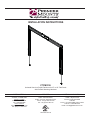
1
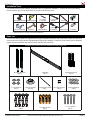
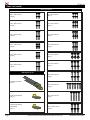
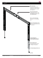
INSTALLATION INSTRUCTIONS PTFM3765 Universal Ultra Low Profile Flat Mount for 37″ to 65″ Flat Panels with ProPack Mounting Hardware NORTH AMERICA EUROPE AUSTRALIA AND OCEANIA 3130 East Miraloma Avenue Anaheim, CA 92806 USA USA and Canada Phone: 1.800.368.9700 Fax: 1.800.832.4888 Other Locations Phone: (001).714.632.7100 Fax: (001).714.632.1044 Swallow House, Shilton Industrial Estate, Shilton, Coventry, England CV79JY Phone: +44 (0) 2476 614700 Fax: +44 (0) 2476 614710 Distributed by Amber Technology Limited Unit B, 5 Skyline Place Frenchs Forest NSW 2086 Australia Phone: +61 2 9452 8600 Sydney Office Toll Free: 1-800-368-9700 Email: [email protected] 9531-222-G01-02 PTFM3765 Contents Weight Limit. ............................................................................................................................................................. 2 Warning Statements. ................................................................................................................................................ 2 Installation Tools. ...................................................................................................................................................... 3 Parts List................................................................................................................................................................... 3 Mounting Hardware. ................................................................................................................................................. 4 Features. .................................................................................................................................................................. 5 Installing the Wall Plate. ........................................................................................................................................... 6 Determining the Viewing Height. ................................................................................................................. 6 Determining the Mounting Surface. ............................................................................................................. 9 Wood Stud Installation................................................................................................................................. 9 Concrete Installation. ................................................................................................................................. 11 Steel Stud Installation. ............................................................................................................................... 13 Mounting Hardware Installation. ............................................................................................................................. 15 Selecting the Mounting Hardware. ............................................................................................................ 15 Universal Washer Installation. ................................................................................................................... 16 Universal Spacer Installation. .................................................................................................................... 16 Mounting Bracket Installation. ................................................................................................................................ 17 Mounting Bracket Extension Installation.................................................................................................... 17 Attaching the Mounting Bracket to the Flat Panel. .................................................................................... 18 Attaching the Flat Panel to the Wall Plate. ............................................................................................................. 18 Removing the Flat Panel. .......................................................................................................................... 19 Technical Specifications. ........................................................................................................................................ 19 Warranty. ................................................................................................................................................................ 20 Weight Limit Maximum Flat Panel Weight: 100 lbs. THE WALL STRUCTURE MUST BE CAPABLE OF SUPPORTING AT LEAST FIVE TIMES THE WEIGHT OF THE FLAT PANEL. IF NOT, THE WALL STRUCTURE MUST BE REINFORCED. Warning Statements PRIOR TO THE INSTALLATION OF THIS PRODUCT, THE INSTALLATION INSTRUCTIONS MUST BE READ AND COMPLETELY UNDERSTOOD. KEEP THESE INSTALLATION INSTRUCTIONS IN AN EASILY ACCESSIBLE LOCATION FOR FUTURE REFERENCE. PROPER INSTALLATION PROCEDURE BY A QUALIFIED SERVICE TECHNICIAN MUST BE FOLLOWED, AS OUTLINED IN THESE INSTALLATION INSTRUCTIONS. FAILURE TO DO SO COULD RESULT IN PROPERTY DAMAGE, SERIOUS PERSONAL INJURY, OR EVEN DEATH. SAFETY MEASURES MUST BE PRACTICED AT ALL TIMES DURING THE ASSEMBLY OF THIS PRODUCT. USE PROPER SAFETY EQUIPMENT AND TOOLS FOR THE ASSEMBLY PROCEDURE TO PREVENT PERSONAL INJURY. PREMIER MOUNTS DOES NOT WARRANT AGAINST DAMAGE CAUSED BY THE USE OF ANY PREMIER MOUNTS PRODUCT FOR PURPOSES OTHER THAN THOSE FOR WHICH IT WAS DESIGNED OR DAMAGE CAUSED BY UNAUTHORIZED ATTACHMENTS OR MODIFICATIONS, AND IS NOT RESPONSIBLE FOR ANY DAMAGES, CLAIMS, DEMANDS, SUITS, ACTIONS OR CAUSES OF ACTION OF WHATEVER KIND RESULTING FROM, ARISING OUT OF OR IN ANY MANNER RELATING TO ANY SUCH USE, ATTACHMENTS OR MODIFICATIONS. At least two qualified people should perform the assembly procedure. Personal injury and/or property damage can result from dropping or mishandling the flat panel. If mounting to wall studs or ceiling studs, make sure that the mounting screws are anchored into the center of the wall studs or ceiling studs. Use of an edge-to-edge stud finder is recommended. It is recommended that a maximum of ⅝″ plaster board be used when mounting to wooden studs. Be aware of the mounting environment. If drilling and/or cutting into the mounting surface, always make sure that there are no electrical wires in wall. Cutting or drilling into an electrical line may cause serious personal injury. Make sure there are no water or natural gas lines inside the wall where the mount is to be located. Cutting or drilling into a water or gas line may cause severe property damage or personal injury. This product is intended for indoor use only. Use of this product outdoors could lead to product failure and/or serious personal injury. Do not install near sources of high heat. Do not install on a structure that is prone to vibration, movement or chance of impact. Contact Premier Mounts with any questions: (800) 368-9700 [email protected] Page 2 Visit the Premier Mounts website at http://www.mounts.com Installation Instructions PTFM3765 Installation Tools The following tools may be required, dependent upon your particular installation. These tools are not provided by Premier Mounts, but you can purchase them at your local hardware store. Electronic Stud Finder Hand Held Drill Hammer** Protective Eyewear ¼˝ Drill Bit /16˝ Drill Bit* 5 Tape Measure /16˝ Concrete 7 Drill Bit** Pencil Level Phillips Tip Screwdriver Socket Wrench ½″ Socket * Optional tools for steel stud installations. ** Optional tools for concrete / steel stud installations. Parts List Your Premier Mounts product is shipped with all proper installation hardware and components. Make sure that none of these parts are missing and/or damaged before beginning installation. If there are parts missing and/or damaged, please stop the installation and contact Premier Mounts (800) 368-9700. PTFM3765 Universal Ultra Low Profile Flat Mount Assembly Components Mounting Brackets (Qty 2) /16″ Flat Washers 5 (Qty 4) Bracket Extensions (Qty 2) Wall Plate (Qty 1) Universal Spacers (Qty 24) Thread Depth Indicator (Qty 1) M4 x 5mm Screws (Qty 4) Universal Washers (Qty 6) ProPack Mounting Hardware M6 Steel Stud Anchors (Qty 4) Installation Instructions /16″ Plastic Anchors 7 (Qty 4) Visit the Premier Mounts website at http://www.mounts.com /16″ x 3″ Lag Bolts 5 (Qty 4) Page 3 PTFM3765 Parts List (cont’d) Mounting Hardware M4 x 16mm Screw (Qty 6) M6 x 16mm Screw (Qty 6) M4 x 25mm Screw (Qty 6) M6 x 25mm Screw (Qty 6) M4 x 30mm Screw (Qty 6) M6 x 30mm Screw (Qty 6) M5 x 16mm Screw (Qty 6) M6 x 45mm Screw (Qty 6) M5 x 25mm Screw (Qty 6) M8 x 16mm Screw (Qty 6) M5 x 30mm Screw (Qty 6) M8 x 25mm Screw (Qty 6) HDMI Right Angle Kit M8 x 30mm Screw (Qty 6) 9′ HDMI Flat Cable (Qty 1) M8 x 45mm Screw (Qty 6) Page 4 Right Angle Adapter (Qty 1) M8 x 70mm Screw (Qty 4) Right Angle Adapter (Reversed) (Qty 1) M10 x 30mm Screw (Qty 6) Visit the Premier Mounts website at http://www.mounts.com Installation Instructions PTFM3765 Features Mounting Slots Allow for a variety of stud configurations and lateral shift adjustments when mounting your flat panel. Expandable Wall Plate Fits flat panels from 37″ wide and expands to support up to 65″ wide flat panels. Ultra Low Profile Design Less than ½″ (.37″) from the wall. Spring Loaded Safety Latch Keeps your flat panel secure to the wall plate. Universal Spacers Uniquely designed spacers that fit multiple screw sizes. Bracket Extensions Fits larger flat panel models including 65″ flat panels. 30″ Braided Nylon Pull Cord Pull Tab Installation Instructions Visit the Premier Mounts website at http://www.mounts.com Page 5 PTFM3765 Installing the Wall Plate Determining the Viewing Height Step 1 You must establish the viewing height of your flat panel prior to installing your PTFM3765 mount. This will result in making long-term viewing of your flat panel more comfortable. Place your flat panel face-down on a soft, flat surface. Use a measuring tape to find the vertical center of your flat panel. Measure from the outer-most top edge to the outer-most bottom edge. Use a pencil and lightly mark the vertical center of your flat panel. Step 2 Use a tape measure to measure the distance between the top mounting points on your flat panel. Is the distance between the mounting points greater than 29.5"? If No, skip to Step 4 . If Yes, proceed to Step 3 . Page 6 Visit the Premier Mounts website at http://www.mounts.com Installation Instructions PTFM3765 Installing the Wall Plate (cont’d) Step 3 Remove the two (2) M4 x 5mm screws. Remove the connector plate. Slide the wall plate halves apart. Replace the connector plate, aligning the outer-most tabs on the connector plate with the slots in the wall plate. Replace and tighten the two (2) M4 x 5mm screws. Before installing the wall plate to the wall you must verify that: ● ● The tabs on the connector plate are seated in the slots in the wall plate. The two (2) M4 x 5mm screws are seated and tightened. Proceed to Step 4 . Step 4 Place the mounting brackets over the flat panel mounting points. Connect the wall plate to the mounting brackets. Do not install any mounting hardware at this time. Connecting the wall plate to the mounting brackets may cause the mounting brackets to move out of position. If this occurs, move the mounting brackets back over the flat panel mounting points after you have locked in the wall plate. Installation Instructions Visit the Premier Mounts website at http://www.mounts.com Page 7 PTFM3765 Installing the Wall Plate (cont’d) Step 5 Use a tape measure to measure the distance from the bottom edge of the wall plate to the centerline mark on the flat panel. Record this measurement on a piece of paper as Distance A. Step 6 Determine whether your flat panel will be viewed from a seated or standing position. When standing or seated, identify a point on the wall in your selected viewing area that is horizontal with your eye level. Use a pencil and lightly mark the wall at the eye level point you identified in Step II. Use a tape measure to measure the distance from the floor to the mark you made at eye level. Record this measurement on a piece of paper as Distance B. Add the values for Distance A and Distance B. Record this measurement on a piece of paper as Distance C. Use a tape measure to measure Distance C on the wall. Use a pencil and lightly mark the wall at Distance C. This will be the location of the bottom of the wall plate. Proceed to the “Determining the Mounting Surface” section. A Center of Flat Panel C B Floor Line Page 8 Visit the Premier Mounts website at http://www.mounts.com Installation Instructions PTFM3765 Installing the Wall Plate (cont’d) Determining the Mounting Surface If you will be installing your PTFM3765 mount to wood studs, proceed to the “Wood Stud Installation” section. If you will be installing your PTFM3765 mount to a concrete surface, proceed to the “Concrete Installation” section. Wo od Co n Ste el cre te Stu d If you will be installing your PTFM3765 mount to steel studs, proceed to the “Steel Stud Installation” section. Stu d Wood Stud Installation Step 1 You must secure the wall plate to two (2) wall studs using two (2) lag bolts; one (1) lag bolt anchored through each wall plate section for each stud found. X Use a stud finder to determine the exact center of wall studs in the vicinity of the wall plate. Use a pencil to mark the exact center of each of the wall studs. X Distance C Pencil Mark Step 2 Two people are recommended for this step; one person to level the wall plate and another person to mark the wall stud location. X Place the wall plate against the wall in the desired viewing location. Align the bottom of the wall plate with the pencil mark you made for Distance C. Adjust the wall plate to align the mount slots in the wall plate with the center of the wall studs. Level the wall plate. Use a pencil to mark the right-hand mounting location along the exact center of the wall stud. Installation Instructions Visit the Premier Mounts website at http://www.mounts.com X Page 9 PTFM3765 Installing the Wall Plate (cont’d) Step 3 Drill a pilot hole in the center of the mark using a ¼″ drill bit and power drill. X Only use a ¼″ drill bit when drilling the pilot holes. X Pilot Holes When a screw is driven into a material, such as wood, it can act as a wedge, generating outward pressure which can cause many materials to split. Drilling a small pilot hole in the material into which the screw will be driven causes less ‘wedging’ to take place, thereby reducing the likelihood of the material being split. It also reduces the possibility of the screw head from being sheared off by torque Step 4 Place the wall plate against the wall and align a mounting slot with the pilot hole. Insert one (1) 5/16″ x 3″ lag bolt and one (1) 5/16″ X washer into the pilot hole and tighten using a socket wrench and ½″ socket. X Do not overtighten the lag bolt. Step 5 Two people are recommended for this step; one person to level the wall plate and another person to drill the pilot holes. X Level the wall plate. Drill a pilot hole in the exact center of the left-hand wall stud using a power drill and a ¼″ drill bit. X Only use ¼″ drill bit when drilling the pilot holes. Page 10 Visit the Premier Mounts website at http://www.mounts.com Installation Instructions PTFM3765 Installing the Wall Plate (cont’d) Step 6 Insert one (1) 5/16″ x 3″ lag bolt and one (1) 5/16″ washer into the pilot hole X Tighten the lag bolt using a socket wrench and ½″ socket. Do not overtighten the lag bolts when attaching the wall plate to the wall. Improper installation may result in personal injury or property damage. X Proceed to the “Mounting Hardware Installation” section. Concrete Installation The supplied 7/16″ plastic anchors and 5/16″ lag bolts must be used for concrete installation. You will need a 7/16″ masonry drill bit, which is available at your closest hardware store. /16″ Plastic Anchors 7 /16″ x 3″ Lag Bolts 5 Example of 7/16″ Masonry Drill Bit (Not Included) Step 1 Two people are recommended for this step; one person to level the wall plate and another person to mark the mounting locations. Place the wall plate against the wall in the desired viewing location. Align the bottom of the wall plate with the pencil mark you made for Distance C. Level the wall plate. Use a pencil and mark three (3) mounting locations where you will be drilling holes for the plastic anchors. Use the mounting hole in the connector plate for the center mounting location. Set the wall plate to one side in a safe location. Installation Instructions Mounting Hole Connector Plate Visit the Premier Mounts website at http://www.mounts.com Page 11 PTFM3765 Installing the Wall Plate (cont’d) Step 2 Do not drill into the mortar joints of cinder blocks. Only drill into a solid part of the cinder block. Use a power drill and 7/16″ masonry drill bit to drill a hole to a depth of 3¼″ at each of the marked mounting locations. Step 3 Insert a plastic anchor into each hole. If necessary, lightly tap each plastic anchor into place with a hammer. Step 4 Place the wall plate against the wall over the plastic anchors and align the mounting slots with the plastic anchors. Insert and partially thread one (1) 5/16″ lag bolt and 5 /16″ washer into each plastic anchor. Level the wall plate. Tighten all 5/16″ lag bolts. Do not overtighten the 5/16″ lag bolts. Proceed to the “Installing the Mounting Bracket” section. Page 12 Visit the Premier Mounts website at http://www.mounts.com Installation Instructions PTFM3765 Installing the Wall Plate (cont’d) Steel Stud Installation The supplied M6 steel stud anchors must be used to install your Premier Mounts’ mount to steel studs. Do not use lag bolts or wood screws. Steel Stud Anchor Screw Steel Stud Anchor Sleeve Step 1 Identify the general location on the wall where you will be mounting your flat panel. Use a stud finder to determine the exact center X of each steel stud in the vicinity of the mounting location. Use a pencil and mark the exact center of each steel stud. X Distance C Pencil Mark Step 2 Place the wall plate against the wall in the desired viewing location. Align the bottom of the wall plate with the pencil X mark you made for Distance C. Adjust the wall plate to match the locations of the steel studs. Level the wall plate. Use a pencil and mark both right and left locations where you will be drilling holes for the steel stud anchors. Set the wall plate to one side in a safe location. Installation Instructions Visit the Premier Mounts website at http://www.mounts.com X Page 13 PTFM3765 Installing the Wall Plate (cont’d) Step 3 Use a power drill and 7/16″ drill bit to drill a hole at each of the marks. Insert a steel stud anchor into each hole. X If necessary, lightly tap each steel stud anchor into place with a hammer. X Step 4 Use a Phillips screwdriver to tighten each steel stud anchor screw until the legs have completely compressed against the back of the steel stud. The steel stud anchor screw will feel tight when you first begin to turn it until the legs begin to compress. The steel stud anchor screw will then turn easier for several turns. The steel stud anchor screw will again feel tight when the legs have completely compressed against the back of the drywall. Stop turning the steel stud anchor screw at that point. Do not overtighten the steel stud anchor screw. Remove the steel stud anchor screws and set them aside. Steel stud anchors may come with small paper washers. You may leave them on the screw or discard them. These small paper washers do not replace standard 5/16″ washers. Page 14 Visit the Premier Mounts website at http://www.mounts.com Installation Instructions PTFM3765 Installing the Wall Plate (cont’d) Step 5 Align the wall plate over the steel stud anchor sleeves. Insert a steel stud anchor screw and a 5/16″ washer into each steel stud anchor sleeve. Use a Phillips screwdriver and tighten each steel stud anchor screw until it is just snug. X Do not overtighten the steel stud anchor screws. X Do not use a power drill to tighten the steel stud anchor screws. Proceed to the “Mounting Hardware Installation” section. Mounting Hardware Installation Selecting the Mounting Hardware Insert the Thread Depth Indicator into the thread inserts found on the back of your flat panel. Use a pencil to mark the depth of the thread insert on the Thread Depth Indicator, as shown in Figure 1. Insert the Thread Depth Indicator into the remaining thread inserts to compare and verify their depth. Locate the correct diameter screw for the thread insert. If the screw you selected is longer than the mark on the Thread Depth Indicator, as shown in Figure 2 and Figure 3, do not use this screw. The screw length must not bypass the mark. Test each size of the screws provided. The correct screws should thread easily into the mount point and not pull out when tension is applied. Proceed to the “Universal Washer Installation” section. Installation Instructions Visit the Premier Mounts website at http://www.mounts.com Page 15 PTFM3765 Mounting Hardware Installation (cont’d) Universal Washer Installation Premier Mounts’ Universal Washers are designed to accommodate the various M4, M5, M6 and M8 hole sizes required by flat panels. M8 M5, M6 M4 Do not place excessive pressure on the back of the flat panel, as this may damage your flat panel. The Universal Washer must be installed between the head of the mounting screw and the mounting bracket as shown. Does your flat panel have: ● ● ● ● ● Power or data connections which face the wall? Recessed mounting points? Uneven mounting points? A curved back? Any obstruction near the mounting point? If No, skip to the “Mounting Bracket Installation” section. Mounting Screw If Yes, you must install Universal Spacers. Remove the mounting brackets, Universal Washers, and mounting screws from the back of the flat panel. Proceed to the “Universal Spacer Installation” section. Universal Washer Mounting Bracket Flat Panel Universal Spacer Installation Universal Spacer Premier Mounts’ Universal Spacers allow you to attach the mounting bracket to flat panels which have recessed or uneven mounting points. Each Universal Spacer adds ¼˝ to the distance between the mounting bracket and your flat panel. Mount Point The Universal Spacers must be stacked and oriented as shown. The Universal Spacers must only be installed between the mounting bracket and your flat panel. The Universal Spacers will fit M4, M5, M6 and M8 screw sizes. There must be sufficient space between your flat panel and the wall for power and data connections. If your flat panel has power or data connections which face the wall, you need to use either a sufficient number of Universal Spacers to allow connections to be made, or use the provided 90° HDMI connectors and cable. 1˝ ¼˝ Power or data connections which improperly force your flat panel away from the wall without the use of Universal Spacers or the supplied HDMI connectors will prevent safe installation of your flat panel. Proceed to the “Mounting Bracket Installation” section. Page 16 Visit the Premier Mounts website at http://www.mounts.com Installation Instructions PTFM3765 Mounting Bracket Installation This section presumes that you have read and understood these sections: ● ● ● Selecting the Mounting Hardware Universal Washer Installation Universal Spacer Installation Use a tape measure to measure the distance between the top and bottom mounting points. Is the distance greater than 16"? If No, skip to the “Attaching the Mounting Bracket to the Flat Panel” section. If Yes, proceed to the “Mounting Bracket Extension Installation” section. Mounting Bracket Extension Installation If the vertical distance between the upper and lower mounting points on your flat panel is greater than 16", then you will need to attach the mounting bracket extensions to the mounting brackets. Mounting bracket extensions add up to 9.75" to the length of the mounting bracket. Place your flat panel screen-side down on a soft, flat surface. Place the mounting brackets on top of the flat panel with an upper mounting point visible through an upper mounting slot. Place the mounting bracket extensions on the mounting bracket. Is the lower mounting point visible through one of the mounting holes? Flat Panel Bracket Extension Mounting Bracket Mounting Hole Mounting Point If No, slide the mounting bracket extension until a mounting point becomes visible through a mounting hole. Proceed to . If Yes, proceed to . Insert two (2) M4 x 5mm screws into each mounting bracket extension (one (1) per mounting point). Repeat through for the remaining mounting bracket extension. Proceed to the “Attaching the Mounting Bracket to the Flat Panel” section. Installation Instructions Visit the Premier Mounts website at http://www.mounts.com Page 17 PTFM3765 Installing the Mounting Bracket (cont’d) Attaching the Mounting Bracket to the Flat Panel Place your flat panel screen-side down on a soft, flat surface. Identify the number and location of the thread inserts on the back of your flat panel. Aligning the holes on each mounting bracket with the thread inserts on the back of your flat panel. Secure each mounting bracket to your flat panel by inserting a minimum of two (2) screws per bracket. Do not overtighten the mounting hardware. Proceed to the “Attaching the Flat Panel to the Wall Plate” section. Attaching the Flat Panel to the Wall Plate Two people are required for this step. When mounting the flat panel to the wall plate, the flat panel must be completely parallel to the wall for correct engagement of the mounting brackets. Lift the flat panel, keeping the flat panel parallel to the wall. Place the back of the mounting brackets against the front of the wall plate. Slide the flat panel downward while keeping the mounting brackets pressed against the wall plate. Engage the mounting hooks of the mounting brackets onto the wall plate. You will hear an audible “click” as the spring-loaded securing latches lock the mounting brackets to the wall plate. Gently push the flat panel to the wall. Adjust and cut the braided nylon pull cord and secure the pull tab. The pull tab should extend no less than 1" from the bottom of the mounting bracket. Do not release the flat panel until both mounting hooks of the mounting brackets are secure on the wall plate. X X Page 18 Visit the Premier Mounts website at http://www.mounts.com Installation Instructions PTFM3765 Attaching the Flat Panel to the Wall Plate (cont’d) Removing the Flat Panel Two people are required for this step. The steps below must be performed at the same time by both people. The braided nylon pull cord must be engaged and held throughout the flat panel removal process. Gently pull down on both braided nylon pull cords. While still pulling down on both braided nylon pull cords, lift the flat panel up. While still pulling down on both braided nylon pull cords, move the flat panel away from the wall. Release both braided nylon pull cords and gently set your flat panel on a safe, flat, soft surface. Technical Specifications All measurements are in inches [millimeters]. Installation Instructions Visit the Premier Mounts website at http://www.mounts.com Page 19 PTFM3765 Warranty PREMIER MOUNTS LIMITED LIFETIME WARRANTY What and Who is Covered by this Limited Warranty and for How Long Premier Mounts warrants this product to be free from defects in material and workmanship for the lifetime of the original owner of this product. The limited warranty is valid only for the original purchaser of the product. What Premier Mounts Will Do At the sole option of Premier Mounts, Premier Mounts will repair or replace any product or product part that is defective. If Premier Mounts chooses to replace a defective product or part, a replacement product or part will be shipped to you at no charge, but you must pay any labor costs. What is Not Covered; Limitations PREMIER MOUNTS DISCLAIMS ANY LIABILITY FOR DAMAGE TO MOUNTS, ADAPTERS, DISPLAYS, PROJECTORS, OTHER PROPERTY, OR PERSONAL INJURY RESULTING, IN WHOLE OR IN PART, FROM IMPROPER INSTALLATION, MODIFICATION, USE OR MISUSE OF ITS PRODUCTS. PREMIER MOUNTS DISCLAIMS ALL OTHER WARRANTIES, EXPRESS OR IMPLIED, INCLUDING WARRANTIES OF MERCHANTABILITY AND FITNESS FOR A PARTICULAR PURPOSE. PREMIER MOUNTS IS NOT RESPONSIBLE FOR INCIDENTAL OR CONSEQUENTIAL DAMAGES, INCLUDING BUT NOT LIMITED TO, INABILITY TO USE ITS PRODUCTS OR LABOR COSTS FOR REMOVING AND REPLACING DEFECTIVE PRODUCTS OR PARTS. SOME STATES DO NOT ALLOW THE EXCLUSION OR LIMITATION OF INCIDENTAL OR CONSEQUENTIAL DAMAGES, SO THE ABOVE LIMITATION OR EXCLUSION MAY NOT APPLY TO YOU. What Customers Must Do for Limited Warranty Service If you discover a problem that you think may be covered by the warranty you MUST REPORT it in writing to the address below within thirty (30) days. Proof of purchase (an original sales receipt) from the original consumer purchaser must accompany all warranty claims. Warranty claims must also include a description of the problem, the purchaser’s name, address, and telephone number. General inquiries can be addressed to Premier Mounts Customer Service at 1-800368-9700. Warranty claims will not be accepted over the phone or by fax. Premier Mounts Attn: Warranty Claim 3130 East Miraloma Ave. Anaheim, CA 92806 How State Law Applies THIS WARRANTY GIVES YOU SPECIFIC LEGAL RIGHTS, AND YOU MAY ALSO HAVE OTHER RIGHTS WHICH VARY FROM STATE TO STATE. Disclaimer Premier Mounts intends to make this manual accurate and complete. However, Premier Mounts makes no claim that the information contained herein covers all details, conditions or variations, nor does it provide for every possible contingency in connection with the installation or use of this product. The information contained in this document is subject to change without notice or obligation of any kind. Premier Mounts makes no representation of warranty, expressed or implied, regarding the information contained herein. Premier Mounts assumes no responsibility for accuracy, completeness or sufficiency of the information contained in this document. ©Premier Mounts 2009 Page 20 Visit the Premier Mounts website at http://www.mounts.com Installation Instructions