Transcript
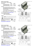
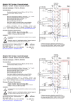
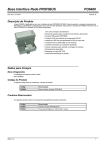
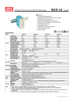
DR-120-24
INSTALLATION AND OPERATION
Mounting Instructions
Mounting: To allow sufficient room for cooling, mount only as shown in the figure, with
the input terminals facing upwards.
Notes On Safety
Read instructions:
Before working with the power supply, read these instructions carefully and
completely, and make sure you understand everything! You should also be sure to
comply with the notes on the unit itself!
Disconnect the system from the supply voltage:
Before installing, doing maintenance, or making modifications, disconnect your
system from the supply voltage. Make sure that any unintended connections in the
circuit are impossible!
Admissible DIN-Rails: TS35/7.5 or TS35/15
For rail fastening:
Before using the unit:
Ensure appropriate installation
Warning! Improper installation/operation may impair safety and result in operating
trouble, or even destruction of the unit.
The unit should only be installed and put into service by appropriately qualified
operators.
Before operating the unit, the following conditions must be checked:
(1) Tilt the unit slightly rearwards.
(2) Fit the unit over the top hat rail.
(3) Slide the unit downwards until it hits the stop.
(4) Press against the bottom to lock in place.
(5) Shake the unit slightly to make sure it is secure.
◎ When using flexible cables, all strands must be properly fastened to the
terminal blocks.
◎ The unit must be properly fused.
◎ All output lines must be rated for the power supply output current and must
be connected with the correct polarity.
o
◎ Use a minimum of 80 C wire.
◎ The terminal torque should be 7 N-m.
2
◎ Connector cables should be 0.5 – 5 mm .
Do not make modifications when operating the unit!
As long as the unit is in operation, do not modify the installation! The same warning
applies to the secondary side of the connection. There exits a risk of electric arcs
and electric shock—which could put your life in danger!
The unit will get very hot! Do not touch the unit when in operation, or shortly after it
is disconnected!
"" Click"
Convective cooling
• Do not cover upper and
lower wall surface!
HOT!
Do not touch side and • Leave sufficient space
rear walls when unit is around the unit for cooling
in operation!
Housing screws are for
internal grounding. Do not
remove them!
11
Not
Allowed
Dimensions
SIZE/WEIGHT
DR-75
● DR-120
●
WIDTH
55.5 mm
65.5 mm
HEIGHT
125 mm
125 mm
DEPTH
100 mm
100 mm
TERMINAL PIN NO. ASSIGNMENTS
TB1:
AC INPUT
TB2:
DC OUTPUT
PIN 1:
PIN 1,2: +V
PIN 2: AC/N
PIN 3,4: -V
WEIGHT
550 g
650 g
PIN3: AC/L
Moxa Technologies Co., Ltd.
Tel: +886-2-8919-1230
Fax: +886-2-8919-1231
www.moxa.com
[email protected]