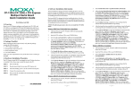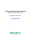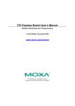
1
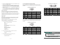
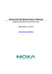
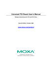
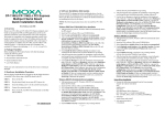
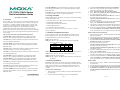
CP-114UL-DB25M: 4-port RS-232/422/485 low profile Universal PCI
board with optical isolation, 0 to 55°C operating temperature (includes
DB25 male cable).
CP-112UL/114UL Series
Quick Installation Guide
First Edition, April 2009
1. Overview
The CP-112UL/CP-114UL series is a 2/4-port RS-232/422/485 Universal
PCI serial board that can be installed in a PC to connect a wide range of
serial devices— including terminals, modems, printers, scanners, cash
registers, bar code readers, keypads, numeric displays, electronic scales,
and data acquisition equipment. It is designed for POS and ATM
applications as well as industrial automation systems. With on-chip
hardware and software flow control, plus a built-in 128-byte Tx/Rx FIFO,
the CP-112UL/CP-114UL series supports data transmission speeds of up
to 921.6 Kbps.
The CP-112UL/CP-114UL series include following models:
CP-112UL-DB9: 2-port RS-232/422/485 low profile Universal PCI
board, 0 to 55°C operating temperature (includes DB9 male cable).
CP-112UL-T: 2-port RS-232/422/485 low profile Universal PCI board,
-40 to 85°C operating temperature.
CP-112UL-I-DB9: 2-port RS-232/422/485 low profile Universal PCI
board with optical isolation, 0 to 55°C operating temperature (includes
DB9 male cable).
CP-112UL-I-T: 2-port RS-232/422/485 low profile Universal PCI board
with optical isolation, -40 to 85°C operating temperature.
CP-114UL-I-T: 4-port RS-232/422/485 low profile Universal PCI board
with optical isolation, -40 to 85°C operating temperature.
2. Package Checklist
Before installing the CP-112UL/CP-114UL series, verify that the package
contains the following items:
y CP-112UL series or CP-114UL series Universal PCI board.
y Standard & low profile bracket.
y Documentation and Software CD-ROM.
y Quick Installation Guide.
y 5-year Product Warranty Statement.
Please notify your sales representative if any of the above items are
missing or damaged.
3. Hardware Installation Procedure
The CP-112UL/CP-114UL series board MUST be installed in the PC
before installing the driver. The following directions as CP-114UL an
example explain how to install the board in the PC.
STEP 1: Power off the PC.
STEP 2: On the CP-114UL, select the serial interface using the DIP
switches as shown below:
Mode
S1
S2
S3
RS-232
----ON
RS-422
--ON
OFF
4-wire RS-485
ON
OFF OFF
2-wire RS-485
OFF OFF OFF
CP-114UL: 4-port RS-232/422/485 low profile Universal PCI board, 0 to
55°C operating temperature.
STEP 3: Plug the board firmly into an open PCI or PCI-X slot on the PC.
CP-114UL-DB9: 4-port RS-232/422/485 low profile Universal PCI
board, 0 to 55°C operating temperature (includes DB9 male cable).
STEP 5: Attach the connection cables.
STEP 6: Power on the PC. The BIOS will automatically set the IRQ and
I/O address.
CP-114UL-DB25: 4-port RS-232/422/485 low profile Universal PCI
board, 0 to 55°C operating temperature (includes DB25 male cable).
CP-114UL-T: 4-port RS-232/422/485 low profile Universal PCI board,
-40 to 85°C operating temperature.
CP-114UL-I: 4-port RS-232/422/485 low profile Universal PCI board
with optical isolation, 0 to 55°C operating temperature.
CP-114UL-I-DB9M: 4-port RS-232/422/485 low profile Universal PCI
board with optical isolation, 0 to 55°C operating temperature (includes
DB9 male cable).
P/N: 1802001142321
—1—
STEP 4: Use the screw to secure the control board into place.
4. Software Installation
Do NOT install the driver until you have physically installed the board.
Please refer to the previous section for instructions on installing the board.
Refer to the Universal PCI User’s Manual for detailed instructions on
installing the drivers. The following installation using CP-114UL as an
example:
Windows Vista (32-bit/64-bit)
1. After powering on your PC, Windows Vista will automatically detect
the serial board.
2. Insert the Document and Software CD in your CD-ROM drive.
—2—
3.
4.
Select Locate and install driver software(recommended).
When you receive a message stating “Windows needs your
permission to continue”, click Next to continue.
5. Select “I don’t have the disc, show me other options”.
6. Select “Browse my computer for driver software(advanced)”.
7. For 32-bit (x86) systems, select the
\CP-114UL\Software\Windows Vista\x86 folder on the CD.
For 64-bit (x64) systems, select the
\CP-114UL\Software\Windows Vista\x64 folder on the CD.
Click Next to continue.
8. If you see a warning that the software has not passed Windows Logo
testing, select Install this driver software anyway.
9. After the driver software has been installed, the installation wizard
will guide you through the port installation, starting with port 0.
10. To verify successful installation, use Windows Device Manager and
check under Multi-port serial adapters and Ports (COM & LPT)
for any special marks, such as a question mark or exclamation point.
Windows 2003 and XP (32-bit/64-bit)
1. After powering on your PC, Windows 2003/XP will automatically
detect the serial board.
2. Insert the Document and Software CD in your CD-ROM drive.
3. Select Install from a list or specific location (Advanced).
4. Select Search for the best driver in these locations, Include this
location in the search, and click Browse.
5. For 32-bit (x86) systems, select the
\CP-114UL\Software\Windows XP_2003\x86 folder on the CD.
For 64-bit (x64) systems, select the
\CP-114UL\Software\Windows XP_2003\x64 folder on the CD.
Click Next to continue.
6. If you see a warning that the software has not passed Windows Logo
testing, select Continue Anyway.
7. After the driver software has been installed, the installation wizard
will guide you through the port installation, starting with port 0.
8. To verify successful installation, use Windows Device Manager and
check under Multi-port serial adapters and Ports (COM & LPT)
for any special marks, such as a question mark or exclamation point.
Windows 2000
1. After powering on your PC, Windows 2000 will automatically detect
the serial board.
2. Insert the Document and Software CD in your CD-ROM drive.
3. Select Search for a suitable driver for my device (recommended).
4. In Optional search location, select specify a location. Select the
\CP-114UL\Software\Windows 2K folder on the CD and click OK
to continue.
—3—
5.
6.
7.
If you see a warning that the software has not passed Windows Logo
testing, select Continue Anyway.
After the driver software has been installed, the installation wizard
will guide you through the port installation, starting with port 0. Be
sure to install the software from the \CP-114UL\Software\Windows
2K folder on the CD.
To verify successful installation, use Windows Device Manager and
check under Multi-port serial adapters and Ports (COM & LPT)
for any special marks, such as a question mark or exclamation point.
Linux (32-bit/64-bit)
Ensure that you are logged into the machine with superuser (root)
privileges. Insert the Moxa driver CD-ROM into the CD-ROM drive.
If necessary, use the mkdir command to create a mount point for the
CD-ROM. The following command creates a mount point in the directory
/cdrom; you can mount the CD-ROM at any location in the machine’s
local file system.
mkdir /cdrom
The commands in the steps below assume the CD-ROM is mounted at
/cdrom. If you mount the CD-ROM at a different location, use that
location when issuing commands.
Mount the CD-ROM drive by entering the following command:
# mount -t iso9660 -o ro /dev/cdrom /cdrom
1.
Execute the following commands from the Linux prompt:
#mount /dev/cdrom /mnt/cdrom
#cd /
#mkdir moxa
#cd moxa
#cp /mnt/cdrom/<driver directory>/mxser.tgz .
#tar xvfz mxser.tgz
#cd mxser
#make clean; make install
#cd /moxa/mxser/driver
#./msmknod
#modprobe mxser
2.
Use the Moxa diagnostic utility to verify the driver status:
#cd /moxa/mxser/utility/diag
#./msdiag
3.
1
The CP-112UL series has a female DB25 connector on the board. Cables
with different connectors are available to help you connect your device to
the board.
1
6
Pin
1
2
3
4
5
6
7
8
RS-232
DCD
RxD
TxD
DTR
GND
DSR
RTS
CTS
RS-422
TxD-(A)
TxD+(B)
RxD+(B)
RxD-(A)
GND
-------
13
14
Male DB9 (CBL-M25M9x2-50)
25
5
9
RS-485 4-wire
TxD-(A)
TxD+(B)
RxD+(B)
RxD-(A)
GND
-------
RS-485 2-wire
----Data+(B)
Data-(A)
GND
-------
Pin
2
3
4
5
6
7
8
20
RS-232
TxD
RxD
RTS
CTS
DSR
GND
DCD
DTR
RS-422
RxD+(B)
TxD+(B)
------GND
TxD-(A)
RxD-(A)
RS-485 4-wire
RxD+(B)
TxD+(B)
------GND
TxD-(A)
RxD-(A)
RS-485 2-wire
Data+(B)
--------GND
--Data-(A)
The CP-114UL series has a female DB44 connector on the board. Cables
with different connectors are available to help you connect your device to
the board.
Male DB9 (CBL-M44M9x4-50)
1
6
Pin
1
2
3
4
5
6
7
8
RS-232
DCD
RxD
TxD
DTR
GND
DSR
RTS
CTS
RS-422
TxD-(A)
TxD+(B)
RxD+(B)
RxD-(A)
GND
-------
5
9
RS-485 4-wire
TxD-(A)
TxD+(B)
RxD+(B)
RxD-(A)
GND
-------
Use the Moxa terminal utility to test the TTY ports:
#cd /moxa/mxser/utility/term
#./msterm #./msterm
—4—
Male DB25 (CBL-M44M25x4-50)
5. Pin Assignments and Cable Wiring
RS-485 2-wire
----Data+(B)
Data-(A)
GND
-------
Click here for online support:
www.moxa.com/support
The Americas:
Europe:
Asia-Pacific:
China:
+1-714-528-6777 (toll-free: 1-888-669-2872)
+49-89-3 70 03 99-0
+886-2-8919-1230
+86-21-5258-9955 (toll-free: 800-820-5036)
© 2009 Moxa Inc. All rights reserved.
Reproduction without permission is prohibited.
—5—
—6—