1
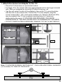
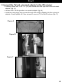
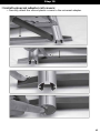
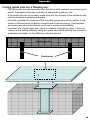
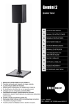
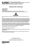
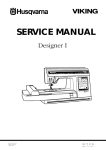
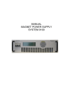
Lift 42 Motorized Flat Panel Lift System with Universal Adapter. ULN # 10235 PN # Lift 42 = L1-10235-PRO-101008vE INSTRUCTION MANUAL IMAGES MAY DIFFER FROM ACTUAL PRODUCT. WARNING – ENGLISH WARNING! SEVERE PERSONAL INJURY AND PROPERTY DAMAGE CAN RESULT FROM IMPROPER INSTALLATION OR ASSEMBLY. READ THE FOLLOWING WARNINGS BEFORE BEGINNING. If you do not understand the instructions or have any concerns or questions, please contact a qualified installer. North America residents can contact OmniMount customer service at 800.668.6848 or [email protected]. Do not install or assemble if the product or hardware is damaged or missing. If you require replacement parts, contact OmniMount Customer Service at 800.668.6848 or [email protected]. International customers need to contact a local distributor for assistance. Do not use this product for any application other than those specified by OmniMount. This product may contain moving parts. Use with caution. DO NOT EXCEED THE MAXIMUM WEIGHT CAPACITY FOR THIS PRODUCT. OMINMOUNT PRODUCT WARRANTY This warranty applies to US Residents who purchase from an authorized OmniMount Dealer. OmniMount products are covered against defects in materials and workmanship for 12 months. OmniMount will repair or replace the defective component or product, at its sole discretion. To obtain warranty service, contact OmniMount customer service at 800.MOUNT.IT (800.668.6848) or [email protected]. You must supply a copy of your original receipt. If your product must be shipped to OmniMount for inspection, you will be responsible for the shipping charges. Replacement product shipped to you will be returned freight pre-paid. OmniMount disclaims any liability for modifications, improper installations, or installations over the specified weight range. To the maximum extent permitted by law, OmniMount disclaims any other warranties, expressed or implied, including warranties of fitness for a particular purpose and warranties of merchantability. OmniMount will not be liable for any damages arising out of the use of, or inability to use, OmniMount products. OmniMount bears no responsibility for incidental or consequential damages. This includes, but is not limited to, any labor charges for the repair of OmniMount products performed by anyone other than OmniMount. This warranty gives you specific legal rights, and you may also have other rights which vary from state to state. Specifications are subject to change without prior notice. WEIGHT CAPACITY ! MAXIMUM WEIGHT CAPACITY Pounds (LBS) Kilograms (KG) MAIN UNIT 125 (lbs) 56 (kg) CAUTION CAUTION: USE WITH PRODUCTS LARGER THAN THE MAXIMUM WEIGHT AND SIZE MAY RESULT IN INSTABILITY CAUSING POSSIBLE INJURY. USER MUST REMOVE TELEVISION OR OBJECT OFF THE BRACKET BEFORE ADJUSTING. MAXIMUM WEIGHT CAPACITY SUPERSEDES / OUTPLACES RECOMMENDED DIAGONAL MEASURED TELEVISION SIZE!! EN: DO NOT EXCEED MAXIMUM OF WEIGHT CAPACITY AND MAXIMUM RECOMMENDED DIAGONALLY MEASURED TELEVISIONS SIZES! 2 Contents Contents 1 1 Base Mount 2 1 Lift Column 3 1 Bayonet Bracket 4 1 Screen Support 5 1 Top Plate 6 1 Control Box 7 1 Remote Control 8 1 IR Receiver/Control switch 9 2 Corner brackets 10 1 Universal Adapter 11 2 Vertical Extension Rails and covers 12 1 Screen Adapter 13 1 Motor cable 14 1 Power cable 3 1 2 5 4 6 7 9 8 10 12 11 13 14 3 Contents Monitor Kit: Parts M-A through M-N are used to connect the TV to the universal adapter. Spacers may be necessary for a proper fit with recessed mounting holes or to allow access to TV inputs. Monitor Kit L-U-vA Pouch # Part # Qty M-A M-A 4 M-B M-B 4 M-C M-C 4 M-D M-D 4 M-E M-E 4 M-F M-F 4 M-G M-G 4 M-H M-H 4 M-I M-I 4 M-J M-J 4 M-K M-K 4 M-L M-L 4 M-M M-M 4 M-N M-N 4 10235vB O 4 P 4 Q 4 R 4 S 4 T 2 U 4 V 4 W 4 X 1 Y 1 Description Philips screws M4 x 15mm Philips screws M4 x 35mm Philips screws M4 x 50mm Philips screws M5 x 15mm Philips screws M5 x 35mm Philips screws M5 x 50mm Philips screws M6 x 15mm Philips screws M6 x 35mm Philips screws M6 x 50mm Philips screws M8 x 15mm Philips screws M8 x 35mm Philips screws M8 x 50mm 5/8" spacer 3/4" spacer M-A M-B M-C M-D M-E M-F Hex screws M6 x 20mm Hex screws M6 x 30mm Philips screws #10 x 3/4" Philips screws #8 x 3/4" Hex screws 3/8-16 x 3/4" 2" x 1/4" Steel guide pins Square washers Felt corner cushions Hex screws 1/4-20 x 1/2" Allen wrench 7/32” Allen wrench 5/32” P M-G M-H M-I M-J V M-K T X Y O Q M-L U S R W M-M M-N 4 Before Installation Prior to enclosure construction and lift assembly, please read through the below warnings and recommendations to ensure a successful installation! PINCH POINT WARNING! • Improper construction of lift enclosure can create dangerous pinch points. It is the responsibility of the installer to ensure the intended use of this product does not create hazardous pinch zones. Installation design should prevent users from inserting objects between moving parts and fixed objects! Failure to do so may result in serious injury or property damage. LIFT STABILITY: • The Lift System should be installed into material at least ¾” thick on both the back and bottom surfaces. The Lift Column is ONLY authorized and tested in a vertical, upright orientation. For enclosures not secured structurally, be sure that enclosure does not create a tip hazard when the lift is in the open position. DO NOT MOUNT THE LIFT SYSTEM UPSIDE DOWN (AS IN A CEILING MOUNT), OR SIDEWAYS (AS IN A LATERAL MOUNT)! ENCLOSURE DIMESIONS: • Before constructing the enclosure carefully consider the dimensions of the TV to be used and the lift mechanism. If possible “dry fit” (see next page) the TV to the lift mechanism prior to building the enclosure to ensure proper fit and function. LARGE TV’S: • With larger televisions the lift unit or lid may need extended to properly fit into the enclosure. The most common application will be to use a spacer block (not included) and corner brackets (part #12) to elevate the lift mechanism to allow for greater TV height. FLOATING TOP: • With floating top installations, it is important to center the lift within the enclosure and center the cabinet top on the lift. With included hardware, the cabinet lid is NOT designated as a weight bearing surface. For safety reasons the cabinet top should be constructed in a “floating” configuration using the guide pins provided to prevent pinch points. See guide pin template in appendix for recommendation. 5 Before Enclosure Construction! Assemble lift mechanism and connect the TV to be used in the install to determine dimensions for the lift enclosure prior to construction. Be sure to leave room for adjustments If necessary. An out of cabinet assembly of the mechanism can be done using steps 1,4,6,8,9 and 10 in order. (D) (D + 2”) (W) (W + 2”) (H) (H + 2”) Minimum INTERIOR Dimensions (H) Minimum Height Height of lift in closed position or Height of TV + 2” NOTE: For use with the longer rails spacers will be needed above and below the lift mechanism (D) Minimum Depth (W) Minimum Width Width of TV + 2” This will allow 1 “ of clearance on either side of the television. Depth of TV + Depth of Mount + 2” Be very careful not to build the enclosure too shallow. The mount may not function or damage to the TV could occur 6 Measurements Required For Cabinetry Dimensions Use previous page to find the minimum INTERIOR dimensions for custom enclosures. Width Depth Height 7 Step 1 Attach the Base Bracket (1) to the Lift Column (2): • Using the small Hex wrench and 6mm x 20mm screws (O), connect the base bracket to the lift column. Note that one side is counter sunk to ensure flush installation of screws. Hand tighten all four screws before proceeding. If the height of the TV to be used is greater than 22” a spacer block will be needed under the base bracket and lift column. 2 1 O x4 8 Step 2 Attach the Bayonet Bracket (3) to the enclosure: • Using the #10 x ¾” screws (Q), attach the bracket so that the top edge of the brackets back plate is 20” above the bottom mounting surface (the bottom of the cabinet or top of the spacer block if used). 3 x4 Q 9 Step 3 Secure Lift Column and Base Bracket in enclosure: • Gently glide the lift column into place on the bayonet bracket so that the tapered slots on the column are secured to the extrusions on the bracket. Gently push down until the base bracket is touching the bottom of the enclosure. DO NOT ATTACH THE BASE BRACKET TO THE MOUNTING SUREFACE AT THIS TIME! • For floating top installations it is recommended that the top of the lift column sits below the lip of the enclosure by 10mm (7/16”) to allow room for the top plate so that the lid sits flush and the guide pins function properly. Figure A 2 Figure B 3 10 Step 4 Connect Screen Adapter (12) to the Screen Support (4): • Use the large hex wrench to secure the screen adapter to the screen support using four 3/8-16 x ¾” screws (S). Depending on TV size and mounting hole pattern the screen adapter can be vertically adjusted for optimal fit. TOP 12 4 12 4 S x4 11 Step 5 Initialize the lift system: • Connect the motor cable to the control box and “pigtail” on the lift column as shown in figures A and B. • Connect the IR receiver/control switch and control box power as shown in figures C and D. • Once all the cables are properly connected, the lift must be initialized by pressing and holding the down button on the IR receiver until the column is at its lowest limit (see figure E for IR receiver orientation). There will be slight raising and lowering of the lift. • Release the down button momentarily before depressing it again for 2 seconds. There will again be a slight movement of the lift, this means the lift is initialized and all previous settings erased. Set the upper limit • Press and hold the up button until the desired top limit is reached, release the up button and depress the down button to stop the lift and set the upper limit. If you want maximum extension, hold the up key until the lift is fully extended and stops before releasing. • The settings will now function when the mechanism is opperated by remote control. In order to reset the programming, disconnect power to the unit and repeat the above steps. Figure A 6 Figure C Figure D 6 6 Figure E IR UP DWN 12 Step 6 Attach the Screen Support(4) and Top Plate(5) to the Lift Column(2): • Before attaching the top plate ensure that the rubber guide on the “pigtail” is secured in the square cutout on what will be the front of the lift column (fig. A). Failure to do so may result in damage to the wire. • Once the pigtail is secure, line up the holes on top of the screen support with the holes in the lift column. Make sure the plate is on the same side as the pigtail, the pigtail will be protected by the screen support (fig. B). Finally line up the holes on the top plate with the holes on the screen support and secure the assembly with four 6mm x 30mm screws (P). Note that top plate is also counter sunk for flush mounting (fig. C). After Before Figure A Figure C Figure B 5 x4 5 4 4 2 13 Step 7 Attach lift assembly to enclosure base: • Using a level on the top plate ensure that the lift column and assembly are level within the enclosure. Gently tap the base of the column left or right to bring the top plate level. • Using four #10 x ¾” (Q) screws attach the base bracket and lift assembly to the enclosure. 2 1 Q x4 14 Step 8 Attach the Universal Adapter to the TV: • Place the TV face down on a protected surface. • For larger TV’s, the vertical rails may need swapped out for the longer included rails. Rails are swapped by removing 2 Phillips screws per rail. • Use the self center function of the adapter to line up the TV’s mounting holes with the slots in the vertical rails. Connect the TV to the adapter using the correct screws (M-A – M-L) and square washers (U). Spacers (M-M and M-N) may be needed if the TV has recessed mounting holes or if inputs are obstructed by the mount. IF SPACERS ARE REQUIRED, THE INSIDE DIMENISIONS OF THE ENCLOSURE MUST ACCOMMODATE THIS NEED! • DO NOT OVERTIGHTEN HARDWARE, DAMAGE TO THE TV MAY RESULT. 10 M-A – M-L M-A – M-L 10 11 Note: IF MONITOR SCREWS “BOTTOM OUT”, THEN USE ADDITIONAL WASHERS (not included) TO TAKE UP THE SLACK. TV 15 Step 9 Connect the TV and universal adapter to the lift column: • Partially install two ¼-20 x ½” (W) hex screws into the top rear of the universal adapter (fig. A). • Lift and lock TV into position on screen adapter (fig. B). • Install two remaining hex screws through the screen adapter into the universal adapter. Hand tighten all 4 hex screws to secure TV to the lift column (fig. C). Figure A Figure B Figure C 16 Step 10 Install universal adapter rail covers: • Carefully attach the correct plastic covers to the universal adapter. 17 Appendix Using guide pins for a floating top: • The guide pins are recommended for use as a safety measure to prevent pinch points. A template has been included to assist with guide pin use. • If the guide pins are to be used, make sure the top surface of the enclosure will not be used as a load bearing surface. • Carefully consider the location of the top plate and guide pins in relation to the center of the enclosure lid before construction of the enclosure. The top plate and guide pins should be directly centered to maximize lid stability. • Improper use of guide pins may result in property damage or injury. If you are unsure or are having difficulty using the guide pins with a floating top, contact a professional installer or OmniMount customer service. Enclosure lid Guide pins 18 Guide Pin/Top Plate Template 19 OmniMount Systems, Inc. 8201 South 48th Street Phoenix, AZ 85044-5355 1-800-MOUNT-IT 1-800-668-6848 www.omnimountpro.com Thank you for purchasing an OmniMount product. 20