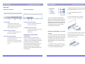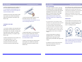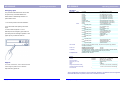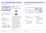
1
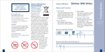
AD-5200A/S
AD-5200A/S
Operating Instructions
Operating Instructions
Part Names and Functions
Laser Safety Information
Disposal of Old Electrical & Electronic
Equipment
(Applicable in the EU and other European
countries with separate collection systems)
This drive employs a laser. Do not remove the
cover or attempt to service this device when
connected due to the possibility of eye
damage.
This symbol on the product or on its packaging
indicates that this product shall not be treated
CAUTION
as household waste. Instead it shall be handed
The use of controls or adjustments or
over to the applicable collection point for the
performance of procedures other than those
recycling of electrical and electronic
specified herein may
equipment. By ensuring this product is
result in hazardous radiation exposure.
materials will help to conserve natural
DVD Writer if the electrical eject is
Eject“ for details)
This panel prevents dust from
entering the Optiarc Writer and
otherwise be caused by inappropriate waste
121mW, 780-788nm; 109mW, 652-663nm
and write operation.
failure occurs. (see „Emergency
environment and human health, which could
handling of this product. The recycling of
Use to remove the disc from the
2. Tray Panel
disposed of correctly, you will help prevent
Semiconductor Laser:
3. Emergency Eject Hole
This indicator lights during data read
disabled by software or if power
potentially negative consequences for the
Laser Specification:
1. Busy Indicator
4. Load/ Eject Button
opens automatically when the
This button is pressed to eject or
Load/Eject button is pushed.
retract the disc tray when the power
is on.
resources. For more detailed information about
recycling of this product, please contact your
local Civic Office, your household waste
disposal service or the shop where you
purchased the product.
Sony Optiarc Europe
1
Sony Optiarc Europe
2
AD-5200A/S
AD-5200A/S
Operating Instructions
Operating Instructions
Rear View
3. Slide the DVD Writer into the computer until
Rear View P-ATA (A)
Rear View S-ATA(S)
it is out approximately 50 ~ 70 mm (2 ~ 3 in.).
4. Locate a spare power cable in your
computer.
5. Connect that power cable to the power
The factory default setting is MASTER for
connector on the back of the DVD Writer.
fitting to enhanced IDE controllers supporting
two ports, one for the hard disk and one for a
5 Jumper Block
DVD Writer. If you prefer to connect the DVD
6s Power Connector (S-ATA)
These blocks of jumper set the
Use this to provide operating power
configuration for the DVD Writer (ref.
from the host computer.
a secondary device) you have to change
jumper setting to SLAVE mode.
chapter ‘Installation of P-ATA drive’s
Jumper Setting’ for details).
Writer to the same port as your hard disc, (as
7s I/O BUS Connector (S-ATA)
This BUS connector is used to control
6a Power Connector (P-ATA)
Use this to provide operating power
the DVD Writer and data
Installing the DVD Writer in a host PC
transmission.
(P-ATA)
from the host computer.
1. Turn off the computer, other peripherals and
Installation of P-ATA drives
7a I/O BUS Connector (P-ATA)
unplug all the cords and cables. Then remove
Jumper Setting
the computer cover, face plate, mounting clips,
This BUS connector is used to control
A jumper consists of a pair of pins and a
the DVD Writer and data
connector, which fits over the pins. When the
transmission. Use a flat ribbon cable
connector is in place it establishes an electronic
to connect your computer to the DVD
link between the pins, which enables the
Writer.
function being controlled by the jumper. If the
6. Connect the I/O BUS connector on the DVD
Writer and the IDE controller. Connect the
Coloured stripe side of the cable on the side
marked with the arrow (V).
and keeper bracket. Refer to the operating
guide that came with your computer for help
with this step.
2. If necessary, remove other devices above
connector is removed, the electronic link is
the installation, approximately 50 ~70 mm (2 ~
disconnected and the function is disabled.
Jumpers are used to set the DVD Writer mode
3 in.), but do not disconnect the cables.
on the interface.
Sony Optiarc Europe
3
Sony Optiarc Europe
4
AD-5200A/S
AD-5200A/S
Operating Instructions
Operating Instructions
7. Slide the DVD Writer into the computer and
Driver Installation
If the reading function is available the next step
fix it in the computer cabinet with 4 screws.
The software installation starts by activating
will be to install a writing/burning software (Not
To avoid damage to the DVD Writer take care
the reading function of the drive (CD-ROM).
supplied with this drive). Please insert your
that the screws do not reach more than 5 mm
If you are using the DVD Writer with Windows
writing software CD-ROM into the DVD Writer
into the DVD Writers cabinet.
95/98/ME/NT/ 200x/XP/Vista or IBM OS/2
and use the information provided with the
Warp, all necessary drivers will be loaded
software (if the installation does not start
8. Replace the mounting clips, keeper bracket,
automatically by the operating system.
automatically you have to activate the software
and computer cover. Refer to the operation
Drivers mentioned above are part of the
installation manually)
guide that came with the computer for help
4. Connect the S-ATA data connector on the
Operating Systems and not available from
with this step.
DVD Writer and the S-ATA controller.
Sony Optiarc.
To avoid transmission errors please do not use
For S-ATA drives: Your computer’s S-ATA
S-ATA cable longer than 50 cm.
connection must support the ATAPI command
set. Some computer motherboards have
Installation of S-ATA
S-ATA RAID chipsets and/or a BIOS that do
drives
Vertical Use
The DVD Writer can be used in the vertical
position. When using the DVD Writer, in the
vertical position, load and unload discs as
shown on the diagram below.
not support the ATAPI command set used by
optical disc drives. If you are unsure, consult
1. Turn off the computer, other peripherals and
your motherboard manual or vendor web site
unplug all the cords and cables. Then remove
for compatibility, BIOS versions and BIOS
the computer cover, face plate, mounting clips,
settings.
and keeper bracket. Refer to the operation
5. Slide the DVD Writer into the computer and
guide that came with your computer for help
fix it in the computer cabinet with 4 screws.
with this step.
To avoid damage to the DVD Writer take care
This drive supports RPC according to
that the screws do not reach more than 5 mm
SFF8090v4 (RPC-2). The final setting
into the DVD Writers cabinet.
/definition of the video region code is
2. Slide the DVD Writer into the computer until
it is out approximately 50 ~ 70 mm.
determined by the fifth DVD video region code
Only 12 cm discs can be used when the DVD
change.
Writer is installed vertically. Do not place 8cm
3. Locate a spare power cable in your
6. Replace the mounting clips, keeper bracket,
computer and connect it to the power
and computer cover. Refer to the operation
connector on the back of the DVD Writer.
guide that came with the computer for help
For Windows 3.xx don’t use the 32 bit hard
with this step.
disk access, because this mode is not
discs in the tray when using the DVD Writer
installed in this way.
supported for DVD drives.
Sony Optiarc Europe
5
Sony Optiarc Europe
6
AD-5200A/S
AD-5200A/S
Operating Instructions
Emergency Eject
Operating Instructions
Data Section
Tranfer Rate
The procedure described below can be used
READ
to open the tray of the DVD Writer if the
EJECT button is disabled by software or a
power failure occurs.
1. Turn off the power to the DVD Writer/PC.
WRITE
2. If a disc inside is still spinning wait until it
stops.
3. Insert a steel rod (about 1.3 mm in
diameter) into the emergency eject hole and
push firmly until the cartridge is ejected. A stiff
paper clip may be used as steel rod.
Write methods
Access Time
Compatibility
In compliance with
DVD-ROM
DVD-R
DVD+R
DVD-R DL
DVD+R9
DVD-RW
DVD+RW
DVD-RAM
CD-ROM, CD-R
CD-RW, CD-ROM XA
CD-DA
DVD+R
supported speeds
DVD+R9
supported speeds
DVD+RW
supported speeds
DVD-R
supported speeds
DVD-R DL
supported speeds
DVD-RW
supported speeds
DVD-RAM
supported speeds
CD-R
supported speeds
CD-RW
supported speeds
Power Consumption
Dimensions ( W x H x D)
Weight
Noise
Storage temperature and humidity
Operating temperature and humidity
Direct Label Print
For further information, various downloads and
hotline support please visit our Website:
http://www.sony-optiarc.eu
3000-7200 Kbytes/sec (48x)
48x/40x/32x/24x/16x/8x
3000-4800 Kbytes/sec (32x)
32x/24x/16x/10x/4x
DAO (disc at once), SAO (session at once), TAO (track at once) with zero gap, variable or
fixed packet, multisession
160 msec
DVD-ROM (1/3 stroke read, average)
CD-ROM (1/3 stroke read, average)
140 msec
DVD-ROM,DVD-Video, DVD±DL, DVD±RW, High Sierra and ISO9660, CD-ROM, CD-ROM
XA, CD-DA, CD-TEXT, CD-I (FMV), Enhanced Music CD (CD+), PhotoCD
(SingleSession/MultiSession), VideoCD (WhiteBook)
MultiRead, PC-2001, MS Vista
General
Memory Buffer
Interface
Support
9-22 Mbytes/sec (6.6-16x CAV)
9-22 Mbytes/sec (6.6-16x CAV)
9-22 Mbytes/sec (6.6-16x CAV)
6.9-16.6 Mbytes/sec (5-12x CAV)
6.9-16.6 Mbytes/sec (5-12x CAV)
7.3-17.5 Mbytes/sec (5-13x CAV)
7.3-17.5 Mbytes/sec (5-13x CAV)
./.
3000-7200 Kbytes/sec (20-48x CAV)
2550-6000 Kbytes/sec (17-40x PCAV)
2550-6000 Kbytes/sec (17-40x PCAV)
11.4-27.5 Mbytes/sec (20x)
20x/18x/16x/12x/8x/6x/4x/2.4x
5.5-11 Mbytes/sec (8x)
8x/6x/4x/2.4x
5.5-11 Mbytes/sec (8x)
8x/6x/4x/2.4x
11.4-27.5 Mbytes/sec (20x)
20x/18x/16x/12x/8x/6x/4x/2x
6.9-16.6 Mbytes/sec (12x)
12x/8x/6x/4x/2x
8.2 Mbytes/sec (6x)
6/x4x/2x/1x
./.
AD-5200S
AD-5200A
2 MBytes
Serial ATA , max. 150 MByte/sec
IDE/Atapi, max 66 Mbytes/sec
max. 31.5 VA , 5V 1.5A; 12V 2A
148x42x170 mm
0.6 kg
47.5dB(A)
-40° to 65° C, 5% to 95% RH, noncondensing
5° to 50° C, 20% to 80% RH, noncondensing
./.
Above specifications are subject to change. Microsoft, Windows, and Windows Vista are registered
trademarks Microsoft Corporation, Photo CD is a trademark of Kodak.
Sony Optiarc Europe
7
Sony Optiarc Europe
8