1
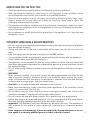
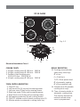
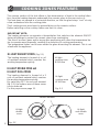
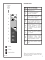
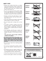
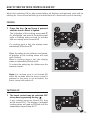
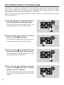
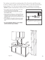
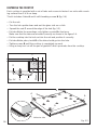
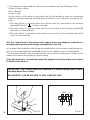
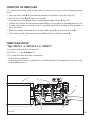
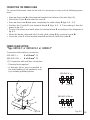
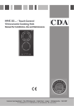
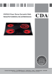
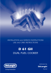
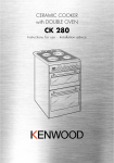
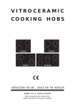
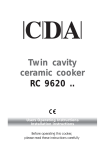
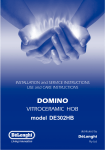
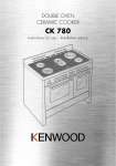
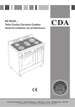
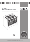
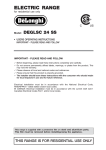
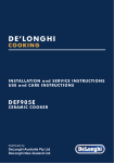
TOUCH CONTROL
VITROCERAMIC
COOKING HOBS
INSTRUCTIONS FOR USE - ADVICE FOR THE INSTALLER
KEEP IN A SAFE PLACE
Before operating this cooking hob,
please read these instructions carefully
Dear Customer,
Thank you for having purchased and given your preference to our
product.
The safety precautions and recommendations reported below are
for your own safety and that of others. They will also provide a means
by which to make full use of the features offered by your appliance.
Please preserve this booklet carefully. It may be useful in future,
either to yourself or to others in the event that doubts should arise
relating to its operation.
This appliance must be used only for the task it has explicitly been
designed for, that is for cooking foodstuffs. Any other form of usage is
to be considered as inappropriate and therefore dangerous.
The manufacturer declines all responsibility in the event of damage
caused by improper, incorrect or illogical use of the appliance.
CE Declaration of conformity
• This hob has been designed for use only as a cooking appliance. Any other use (e.g.
heating rooms) should be considered incorrect and therefore dangerous.
• This hob has been designed, constructed and put on to the market in conformity with:
- Safety requirements of the "Low Voltage" Directive 73/23/EEC;
- Protection requirements of the "EMC" Directive 89/336/EEC;
- Requirements of Directive 93/68/EEC.
IMPORTANT INFORMATION FOR CORRECT DISPOSAL OF THE PRODUCT IN
ACCORDANCE WITH EC DIRECTIVE 2002/96/EC.
At the end of its working life, the product must not be disposed of as
urban waste. It must be taken to a special local authority differentiated
waste collection centre or to a dealer providing this service.
Disposing of a household appliance separately avoids possible negative
consequences for the environment and health deriving from inappropriate disposal and enables the constituent materials to be recovered to
obtain significant savings in energy and resources. As a reminder of the
need to dispose of household appliances separately, the product is
2 marked with a crossed-out wheeled dustbin.
BEFORE USING FOR THE FIRST TIME
• Read the instructions carefully before installing and using the appliance.
• After unpacking the appliance, make sure it is not damaged. In case of doubt, do not
use the appliance and contact your supplier or a qualified engineer.
• Remove all packaging and do not leave the packing material (plastic bags, polystyrene, bands etc) in easy reach of children as they may cause serious injury. The
packaging materials are recyclable.
• The appliance should be installed and all the electrical connections made by a qualified engineer in compliance with local regulations in force and following the manufacturer’s instructions.
• Do not attempt to modify the technical properties of the appliance, as it may become
dangerous to use.
IMPORTANT SAFEGUARDS & RECOMMENDATIONS
• Do not carry out any cleaning or maintenance without first disconnecting the appliance
from the electrical supply.
• During and after use of the hob, certain parts will become very hot. Do not touch hot
parts.
• After use always ensure that the controls are in the OFF position.
• Young children should be supervised to ensure that they do not play with the appliance.
• Keep children away from the hob during use.
• The appliance is not intended for use by young children or infirm persons unless they
have been adequately supervised by a responsible person to ensure that they can use
the appliance safely.
• Do not allow young children or infirm persons to use the appliance without your supervision.
• WARNING
When correctly installed, your product meets all safety requirements laid down for this
type of product category. However special care should be taken around the underneath of the appliance as this area is not designed or intended to be touched and may
contain sharp or rough edges, that may cause injury.
• Fire Risk! Do not leave inflammable materials on the Hob top.
• Make sure that electrical cords connecting other appliances in the proximity cannot
come in to contact with the Hob top.
• Do not allow heavy or sharp objects to drop on the glass ceramic hob. If the hob is
cracked or damaged , unplug and call the after-sales service.
• Do not scratch the hob with sharp objects. Don’t use the hob as a work surface.
• Before disposing of an unwanted appliance, it is recommended that it is made inoperative and that all potentially hazardous parts are made harmless.
• Important: This appliance has been designed for domestic use only. The appliance is
NOT suitable for use within a semi-commercial, commercial or communal environment.
• If the supply cord is damaged, it must be replaced by the manufacturer or its service agent or a similarly qualified person in order to avoid a hazard.
3
1
FEATURES
60 cm models
3
2
1
4
Fig. 1.1
7
8
13
6
9
5
10
Electrical insulation Class I
COOKING POINTS
DISPLAY DESCRIPTION
1. Hi-light cooking zone Ø 180 mm - 1800 W
2. Hi-light cooking zone Ø 140 mm - 1200 W
3. Hi-light cooking zone Ø 180 mm - 1800 W
4. Hi-light cooking zone Ø 140 mm - 1200 W
13. Cooking zone indicator
(near every zone key):
TOUCH-CONTROL DESCRIPTION
5. ON/OFF key
6. Left front zone (1) key and increasing power
7. Left rear zone (2) key and increasing power
8. Right rear zone (3) key and increasing power
9. Right front zone (4) key and increasing power
10. Decreasing power key (for all cooking zones)
4
0 = Line
L = Child lock
1 ÷ 9 = Zone power level
A = Automatic heating
H = Zone residual heat
60 cm models
2
3
1
4
Fig. 1.2
15
7
8
14
12
13
11
6
9
5
10
Electrical insulation Class I
COOKING POINTS
DISPLAY DESCRIPTION
1. Hi-light cooking zone Ø 180 mm - 1800 W
2. Hi-light cooking zone Ø 140 mm - 1200 W
3. Double hi-light cooking zone
Ø 210/120 mm - 2200/750 W
4. Hi-light cooking zone Ø 140 mm - 1200 W
13. Cooking zone indicator
(near every zone key):
TOUCH-CONTROL DESCRIPTION
5. ON/OFF key
6. Left front zone (1) key and increasing power
7. Left rear zone (2) key and increasing power
8. Right rear zone (3) key and increasing power
9. Right front zone (4) key and increasing power
10. Decreasing power key (for all cooking zones)
11. ON/OFF outside zone of double cooking zone (3)
12. Minute minder or automatic cooking timer key
0 = Line
L = Child lock
1 ÷ 9 = Zone power level
A = Automatic heating
H = Zone residual heat
14. Outside zone ON (double
cooking zone only)
15. Time of minute minder or
automatic cooking time.
The 4 points around the
number indicate what
zone is programmed.
5
60 cm models
2
3
1
4
Fig. 1.3
15
7
8
14
12
14
13
11
6
Electrical insulation Class I
9
5
10
COOKING POINTS
DISPLAY DESCRIPTION
1. Double hi-light cooking zone
Ø 180/120 mm - 1700/700 W
2. Hi-light cooking zone Ø 180 mm - 1800 W
3. Oval double hi-light cooking zone
Ø 150 x 260 mm - 1100/2000 W
4. Hi-light cooking zone Ø 140 mm - 1200 W
13. Cooking zone indicator
(near every zone key):
TOUCH-CONTROL DESCRIPTION
5. ON/OFF key
6. Left front zone (1) key and increasing power
7. Left rear zone (2) key and increasing power
8. Right rear zone (3) key and increasing power
9. Right front zone (4) key and increasing power
10. Decreasing power key (for all cooking zones)
11. ON/OFF outside zone of double cooking zone (1-3)
6 12. Minute minder or automatic cooking timer key
0 = Line
L = Child lock
1 ÷ 9 = Zone power level
A = Automatic heating
H = Zone residual heat
14. Outside zone ON (double
cooking zone only)
15. Time of minute minder or
automatic cooking time.
The 4 points around the
number indicate what
zone is programmed.
80 cm models
2
3
1
4
Fig. 1.4
15
7
8
14
12
14
13
11
Electrical insulation Class I
6
9
5
10
COOKING POINTS
DISPLAY DESCRIPTION
1. Double hi-light cooking zone
Ø 210/120 mm - 2200/750 W
2. Hi-light cooking zone Ø 140 mm - 1200 W
3. Oval double hi-light cooking zone
Ø 180 x 260 mm - 800/2200 W
4. Hi-light cooking zone Ø 140 mm - 1200 W
13. Cooking zone indicator
(near every zone key):
TOUCH-CONTROL DESCRIPTION
5. ON/OFF key
6. Left front zone (1) key and increasing power
7. Left rear zone (2) key and increasing power
8. Right rear zone (3) key and increasing power
9. Right front zone (4) key and increasing power
10. Decreasing power key (for all cooking zones)
11. ON/OFF outside zone of double cooking zone (1-3)
12. Minute minder or automatic cooking timer key
0 = Line
L = Child lock
1 ÷ 9 = Zone power level
A = Automatic heating
H = Zone residual heat
14. Outside zone ON (double
cooking zone only)
15. Time of minute minder or
automatic cooking time.
The 4 points around the
number indicate what
zone is programmed.
7
2
COOKING ZONES FEATURES
The ceramic surface of the hob allows a fast transmission of heat in the vertical direction, from the heating elements underneath the ceramic glass to the pans set on it.
The heat does not spread in a horizontal direction, so that the glass stays “cool” at only
a few centimeters from the cooking plate.
The 4 cooking zones are shown by painted disks on the ceramic surface.
Before switching on the cooktop make sure that it is clean.
IMPORTANT NOTE:
The heating elements incorporate a thermolimiter that switches the element ON/OFF
during all settings to protect the ceramic glass from overheating.
The use of incorrect pans and/or wrong pan positioning will cause the temperature limiter to operate more frequently, resulting in a reduction of cooking performance.
The temperature limiter can be seen under the glass dissecting the element. This is not
a fault with the appliance.
HI-LIGHT RADIANT ZONES
(Fig. 2.1)
The heating element is formed of a coil
of resistant material which reaches the
working temperature quickly.
Hi-light
cooking zone
Ø 140 mm
HI-LIGHT DOUBLE ZONE and
HI-LIGHT OVAL ZONES
The heating element is formed of a 2
coils of resistant material which reaches
the working temperature quickly.
By switching OFF the second element
(fig. 2.2), the surface area of these zones
can be reduced.
For this purpose see page 15.
Hi-light
cooking zone
Ø 180 mm
Fig. 2.1
Second element
Hi-light
double
zone
8
Fig. 2.2
Hi-light
oval double
zone
CO0KING HINTS
Cooking
zone
power
level
Power
level
TYPE OF COOKING
0
Switched OFF
1
2
For melting operations
(butter, chocolate).
3
To maintain food hot and to
heat small quantities of
liquid (sauces, eggs).
4
5
To heat bigger quantities; to
whip creams and sauces.
(vegetables, fruits, soups).
5
6
Slow boiling, i.e.:
meats, spaghetti,
continuations of
cooking of roasts,
potatoes.
6
For every kind of frying,
cutlets, uncovered cooking,
i.e.: risotto.
8
7
8
Browning of meats, roasted
potatoes,
fried
fish,
omelettes, and for boiling
large quantities of water.
9
9
Fast frying, grilled steaks,
etc.
1
2
3
4
5
6
boiled
soups,
steam
stews,
7
Heating
Cooking
Roasting-frying
Fig. 2.3
After a short period of use, experience
will teach you which setting is the right
one for your needs.
9
RESIDUAL HEAT INDICATOR
When the temperature of a cooking plate is over 60°C, the relevant
trol display is also lit-up to warn of heat on the surface of the hob.
H in the touch con-
This H symbol also stay on after the cooking plate has been switched off to shown that
the hob surface is still hot.
This residual heat lasts for a rather long time after the cooking plate has been switched
off.
During this time you should avoid touching the hob surface over the cooking area.
Please pay special attention to ensure that children are not allowed near
the hob.
The H symbol will switch off automatically as soon as the surface temperature of the
cooking plate falls below 60 °C.
COOKING HINTS
– To reduce the cooking time, you can set the fast cooking function (cf. section “FAST
AUTOMATIC HEATING OF THE COOKING ZONES” at page 16).
– You should use pots and pans with flat bases (pans with the test mark for glassceramic hobs are available from specialist shops).
– The diameter of the pan should match that of the cooking plate (or be slightly bigger)
to make the most of the energy.
– Since the cooking surface stays hot for a certain time after the plate has been
switched off, you can switch it off 5 or 10 minutes before the end of the cooking.
The residual heat of the hob will complete the cooking.
– To save electricity, use pan lids whenever possible.
Never cook the food directly on the glass ceramic cooktop, but in special pans
or containers.
WARNING: Hobs become very hot with use, and retain their heat for a long time
after cooking has finished (about 30 minutes).
Children should be supervised at all times and be prevented from touching the
hot surfaces, until such time as the appliance has cooled.
10
SAFETY HINTS
• Before you switch the hob on, make
sure you know which touch controls the
required cooking zone. We advise you
to set the pan over the cooking zone
before switching it on.
DISTORTED
PANBASE
• Do not use pots and pans with rough
bases (pay attention to cookware made
of cast-iron). Rough bases can damage
the glass surface of the hob (scratches).
DISTORTED
PANBASE
• Always ensure that the base of your
saucepan is clean and dry before placing on the hob.
• Pots with aluminium bottoms may leave
silver streaks or spots on the hob.
WRONG
WRONG
LEVEL
PANBASE
CORRECT
• Do not leave wet or damp lids on the
hob.
• The glass-ceramic surface and pans
must be clean. Carefully eliminate any
food remains (especially containing
sugar), dirt etc. with the aid of a cleansing agent.
WRONG
WASTING
POWER
• Pan handles should never stand out
beyond the kitchen worktop, as there is
a great danger of knocking the pan
over.
This will also ensure that children
cannot reach them.
WRONG
• Do not use the hob if the glass surface is broken or cracked in any way.
Please disconnect the hob from the
mains and contact the after-sales
service.
WASTING
POWER
• Do not lean over the cooking plate
when in use.
CORRECT
• Do not lay cooking foil or plastic materials on the ceramic surface when it is
hot.
• Remember that the surface remains hot
for a long time (about 30 min.) after the
cooking plate has been switched off.
WASTING
POWER
WRONG
COMPLETE USE
OF THE HEAT
Fig. 2.4
DO NOT USE GLASSWARE ON CERAMIC HOBS.
DO NOT USE PANS WITH ROUGH CIRCULAR MACHINED BASE.
• Follow the cleaning instructions carefully.
• Never use the glass surface for storage.
Fig. 2.5
11
3
HOW TO USE THE TOUCH CONTROL
NOT AVAILABLE IN THE MODEL IN FIG. 1.1
• Minute minder key.
• Program key for automatic
turning off the cooking zone.
Turn-off key for outer
cooking zone (only for
2-circuit zones)
• Dial clock display.
• Display automatic turn-off of the cooking zone
with luminous points showing the involved
zone.
Luminous point indicating that
both circuits of the double circuit
zone are turned ON.
Turn ON and OFF touch
control
Control keys for activation and adjustment of cooking zone power level
Each
key indicates the relevant cooking zone.
The
key is the same for all cooking zones
DISPLAY MESSAGES NEXT TO
TOUCH CONTROL KEYS:
0 = Cooking zone turned OFF.
1-9 = Power range of lighted cooking zone.
A = Automatic heating (in alternation with the preset power level).
H = Afterheat. It is cancelled when the temperature drops below 60 °C.
L = Locked touch control - for children's safety.
12
HOW TO TURN THE TOUCH CONTROL ON AND OFF
When first switching ON or after power failure, all displays and luminous point will be
blinking for 1 second and will then go out while the touch control will be put in stand-by.
STARTING
•
Press the key
and keep it pressed
until the touch control is lighted.
The 4 displays of the cooking zones read 0.
On all displays, the point at the bottom right
sight is blinking every second to indicate
that no cooking zone is turned ON
If a cooking zone is hot, the display reads
alternatively H (hot) and 0.
When the safety key for children is activated,
all displays of the cooking zones will read
out L (locked).
When a cooking zone is hot, the display
reads out alternately H (hot) and L.
To unlock the safety key for children see the
relevant chapter.
Note: If a cooking zone is not turned ON
within 20 seconds after the touch control is
pressed or the timer is not activated, the
touch control will switch off.
SWITCHING OFF
•
The touch control may be switched OFF
at any time by pressing the key
.
If any cooking zones are turned ON, they
will be turned OFF. The display of activated
cooking zones will read out H (hot) until the
temperature drops below 60 °C.
13
POWER IGNITION AND ADJUSTMENT OF A COOKING ZONE
To turn ON a cooking zone its touch control must be switched ON (cf. section “HOW TO
TURN THE TOUCH CONTROL ON AND OFF”).
1. Press the key
to activate the cooking
zone to be lighted; then release the key.
The point of the selected zone on the bottom right side of the display remains lighted
while the points of all other cooking zones
are turned OFF.
If the activated zone is hot, the display will
alternately readout H and 0.
Luminous
point
2. Press
the key
and keep it pressed
until the desired power level, ranging
between 1 and 9 is set.
As an alternative, press the central key
. The choice starts from level 9 (maximum level) down to 1 (minimum level)
The display shows the preset power level; the
point at the bottom right side remains lighted
for 10 seconds. Adjustment will remain possible as long as the point is lighted.
or
POWER ADJUSTMENT OF A HEATED COOKING ZONE
1. Press
the key
to activate the cooking
zone to be adjusted, and then release the
key.
The point at the bottom right side will light
up to indicate the activation.
Luminous
point
2. Press
the key
or
and keep it
pressed until the desired power level is
set.
14
The display will readout the newly preset
power level; the luminous point at the bottom right side remains lighted for 10 seconds Adjustment will be possible as long as
this point is lighted.
or
FUNCTIONING OF THE DOUBLE AND OVAL COOKING ZONES
The double and oval cooking hobs are
consisting of two circuits, which may be
used in the following modes:
• Extended cooking zone: the first and
second heating circuit are both switched
ON.
• Reduced cooking zone: only the first
heating unit is switched ON.
When the double or oval zone are turned
ON, the first and second heating circuit will
both light up at the same time when operating as described in the section: "POWER
IGNITION AND ADJUSTMENT OF A
COOKING ZONE".
DOUBLE ZONE
Second
First
heating
heating
circuit
circuit
turned ON turned ON
OVAL ZONE
Second
heating
circuit
turned ON
First
heating
circuit
turned ON
Luminous
point
The point next to the display will light up to
show that both circuits are switched ON.
SWITCHING THE SECOND HEATING CIRCUIT OF THE DOUBLE AND OVAL
COOKING ZONES OFF AND ON AGAIN
The second circuit of these cooking zones
may be switched OFF and then switched
ON again at any moment.
1. Press the
key to turn OFF the second heating circuit.
The point is
switched
OFF
The luminous point on the display will
be turned OFF.
The second heating circuit of the double
or oval cooking zone will be switched
OFF. Only the first heating circuit
remains ON.
DOUBLE ZONE
OVAL ZONE
2. Press
the
key to turn the second
circuit ON again.
The point on the display will light up
again.
The second circuit of the double or oval
cooking hob will be turned ON.
Second
heating
circuit
turned OFF
First
heating
circuit
turned ON
Second
heating
circuit
turned OFF
First
heating
circuit
turned ON
15
FAST AUTOMATIC HEATING OF THE COOKING ZONES
This function permits fast heating up at the maximum power level, followed by heating
at the preset power level. The duration of the automatic fast heating up period is preset
and depends on the selected power level (cf. schedule)
The touch control shall be switched ON (cf. section “HOW TO TURN THE TOUCH CONTROL ON AND OFF”)
1. Press the
key to activate the interested cooking zone; then release the key.
The point on the bottom right side of the
display will light up to indicate activation.
2. Press
the key
to select the power
level n. 9; then release the key.
The display will readout 9 and the point on
the bottom right side will be illuminated.
3. Press
the key
to activate the fast
heating up function; then release the key.
The display reads out A and the point on the
bottom right side is illuminated.
4. Press
the key
and keep it pressed
until the desired power level ranging
between 1 and 9 is reached.
The display show the preset power level and
the point on the bottom right side is illuminated.
16
This point
will
light up
After a few seconds, the display reads A (automatic) alternatively with the preset power level.
The cooking zone will operate at its maximum
power for the time indicated in the schedule.
Upon its expiry, A on the display will be
switched off and the cooking zone will continue
to function at the preset power level.
Cooking zone
power level
1
2
3
4
5
6
7
8
9
Fast
heating time
1
min.
3
min.
5
min.
6,5
min.
8,5
min.
3,5
min.
3,5
min.
4,5
min.
10
sec.
POWER LEVEL MODIFICATION DURING AUTOMATIC FAST HEATING UP
It is possible to increase but not to reduce the preset power level during fast heating up.
1. Press the key
to activate the interested cooking zone, then release the key.
The point at the bottom right side of the display will light up to indicate activation.
2. Press
the key
until the desired new
power level is reached.
After a few seconds, the display will readout
A (automatic) in alternation with the new
power level setting
INTERRUPTION OF AUTOMATIC FAST HEATING UP
1. Press the key
to activate the interested cooking zone, then release the key.
The point at the bottom right side of the display will light up to indicate activation.
2. Press the key .
A on the display will disappear but the power
level will remain lighted.
17
TURNING OFF THE COOKING ZONE
1. Press the key
to activate the cooking
zone to be switched off; then release the
key.
The point at the bottom right side of the display will light up to indicate activation
2. Method A
Press the keys
time .
and
at the same
The cooking zone is turned OFF and the
display reads out alternately 0 and H indicating the zone is hot.
Method B:
Press the central key
and keep it
pressed until the display reads out 0.
The cooking hob is turned OFF and the display reads out alternately 0 and H indicating the hob is hot.
ALL LIGHTED COOKING ZONES ARE TURNED OFF AT THE SAME TIME
1. Press the key
.
The touch control is switched OFF and all
cooking zones are turned ON.
The displays of turned ON cooking zones
and which have still hot zones will readout H
(hot).
18
This point
will
light up
PROTECTION AGAINST UNWANTED TURN-ON
If the touch control finds that a key remains activated for more than 10 seconds, it will
lock down and sends an audio warning signal to indicate the presence of an object on
the keys.
The displays read out the error code
and a 10 sec. audio warning signal is emitted.
If a cooking zone is hot, an H will be displayed
alternately with an error signal.
The touch control will remain locked (no
control can be activated) unless the object
is removed.
AFTERHEAT IN COOKING ZONES
Whenever H (hot) appears on displays, it means that the temperature of cooking zone
is too warm to be touched.
H is turned OFF when the cooking hob temperature drops below 60 °C.
OPERATION TIME LIMIT OF COOKING ZONES
Each cooking zone is automatically switched
OFF after a maximum preset time if no operation is performed.
The maximum preset time limit depends on the
set power level, as illustrated in this schedule.
Each operation on the cooking hob by using
the keys
,
and
, will reset the maximum operation time at its initial value.
Power level of
Cooking zones
Operation
time limit
1
2
3
4
5
6
7
8
9
6 hours
6 hours
5 hours
5 hours
4 hours
90 minutes
90 minutes
90 minutes
90 minutes
19
SAFETY KEY-LOCK TO PROTECT CHILDREN
This function locks the touch-control keys against unwanted activation.
When set, this function remains permanent, even after the touch control is switched
OFF and turned ON again and even after power failure or black-out.
The safety lock can only be deactivated by a wilful operation.
Before using the cooking zones, it is necessary temporarily to remove the safety locks
which will be automatically reset after the touch-control is switched OFF.
ACTIVATION OF THE CHILDREN'S PROTECTING SAFETY LOCK
1. Press
the key
is turned on.
until the touch control
All four displays of the cooking zones readout 0. The points at bottom right side blink.
2. Press the key
at THE BOTTOM RIGHT
SIDE and the key
together at the
same time; then release these keys.
3. Once
more press the key
BOTTOM RIGHT SIDE.
L
at THE
(locked) appears on the display. If the
cooking hob is hot, L and H will visualized
alternately.
In these conditions, no control except the
turn ON and OFF touch control push button
can be used.
20
TEMPORARILY UNLOCKING OF THE KEYS FOR COOKING PURPOSES
After they have been switched ON, the touch control displays readout four L indicating
that the keys are locked.
To temporarily unlock the keys, which remains active until the touch control is switched
OFF:
•
Press the key
at THE BOTTOM RIGHT
SIDE and the key
together at the
same time.
The four L will be replaced by four 0 with
blinking points to show that all keys have
been unlocked and are activated.
The keys remain activated until the touch
control is switched OFF. When turned ON
again, the safety lock will be reactivated and
the displays will readout four L.
ELIMINATION OF THE CHILDREN'S PROTECTING SAFETY LOCK
1. With touch control switched ON press the
key
at THE BOTTOM RIGHT SIDE and
the key
together at the same time;
then release the keys.
L is replaced by 0 with its blinking point
indicating that the regulation keys have been
activated.
2. Once more press key
.
From now on, the children's protecting NOT
be reactivated after the touch control is
switched OFF.
To reset the safety lock, follow the instructions for activation.
21
PROGRAM FOR AUTOMATIC SWITCHING OFF THE COOKING ZONES
(NOT AVAILABLE FOR MODEL IN FIG. 1.1)
- This function permits to set a timer from 1 to 99 minutes for automatic turning OFF
the cooking zones.
- As many luminous points as there are cooking zones are located around the timer display to indicate the zone on which the timer is activated.
To set the automatic switching OFF program, the cooking zone shall be turned ON
and adjusted at the required power level.
1. The luminous point next to the display of
the cooking zone to be programmed,
shall be blinking. If not, press the
key
to activate the blinker.
The point at the bottom right side of the display will light up to indicate its activation.
2. Press
the timer key
; then release the
Luminous
point
Cooking zone luminous point
key.
The timer display will readout 00 and will
visualize the blinking point of the involved
cooking zone.
3. Method A
Setting in the 0 to 99 minutes range.
Press the timer key
and keep it
pressed until the desired setting is
achieved.
To count back, press the key
.
Note: Each pressure on the timer
or
key, will increase the setting by 1 second,
but a continuous pressure will cause a dynamic increase at a growing speed.
22
Method B
Fast adjustment at 60 minutes.
Press the key
; then release this key.
The display will readout 60.
It will be possible to increase this time up
to 99 minutes by pressing the timer key
within 10 seconds.
The time may be decreased by pressing
the key
.
The count down starts immediately after the
setting has been completed and the luminous
point indicating the cooking zone remains stably lighted.
All cooking zones may be programmed at the
same time.
The timer display will visualize the time set for
the latest selected cooking zone.
I I I
I I I I I
I I I
I I I I I
Upon expiry of the preset time:
- the cooking zone will be turned OFF.
- the display of the cooking zone will readout H.
- the timer display will readout 00 and will be
blinking.
- a sound signal will be activated for 2 minutes
but may be silenced by pressing any pushbutton.
- If no other cooking zone has been programmed the timer display will switch OFF.
- In no other cooking zone is lighted, the touch
control will disconnect after 20 seconds.
23
CONTROL AND/OR MODIFICATION OF THE TIME STATE OF THE PROGRAMMED ZONES
(NOT AVAILABLE FOR MODEL IN FIG. 1.1)
The time state of each cooking zone and its
preset automatic turning off may be visualized
at any moment.
Latest
selected
zone
The display will visualize the time of the latest
selected zone.
To visualize the time state of another programmed zone, proceed as follows:
This point
will
light up
1. Press the key
to activate the interested cooking zone; then release the key.
The point at the bottom right side of the display will light up to confirm its activation.
2. Press the timer key
; then release this
key.
The time left before expiry will be readout on
the display of the involved zone.
3. To
change the time, press the timer key
to increase and the key
to shorten
the time.
or
24
MINUTE MINDER (NOT AVAILABLE FOR MODEL IN FIG. 1.1)
This function permits to set an audio signal that is activated upon expiry of the countdown time, to be programmed in the 1 – 99 range.
This function has no influence on the operation of the cooking hobs.
The touch control shall be switched ON (cf. section HOW TO SWITCH THE TOUCH
CONTROL ON AND OFF).
1. Press the timer key
; then release this
key.
The timer display will light up and readout
00; the point at the bottom right side will be
blinking.
2. Method A
Setting between 0 and 99 minutes.
Press the timer key
and keep it
pressed until the required setting is
achieved. To count back, press
.
Method B
Fast adjustment at 99 minutes:
Press the key
; then release this key.
The display will readout 60.
The time may be increased up to 99minutes by pressing the timer key
within
10 seconds. The time may be decreased
by pressing the key
.
The count-down starts immediately after the time has been set.
Upon expiry, the timer display will readout 00 and will be blinking and an audio signal
will last for 2 minutes but may be silenced by pressing any pushbutton.
25
4
CLEANING AND MAINTENANCE
CLEANING THE CERAMIC HOB
Before you begin cleaning make sure that the hob is switched off.
• Remove spillages and other types of incrustations.
• Dust or food particles can be removed with a damp cloth.
• If you use a detergent, please make sure that it is not abrasive or scouring. Abrasive
or scouring powders can damage the glass surface of the hob.
• All traces of the cleaner must be removed with a damp cloth.
• Dust, fat and liquids from food that has boiled over must be removed as soon as possible.
• If they are allowed to harden they become increasingly difficult to remove.
This is especially true in the case of sugar/syrup mixtures which could permanently pit the surface of the hob if left to burn on it.
• If any of these products has melted on the ceramic surface, you should remove it
immediately (when the surface is still hot) by using a scraper to avoid any permanent
damage to the surface of the hob.
• Do not put articles on the hob which can melt: i.e plastic, aluminium foil, sugar, sugar
syrup mixtures etc.
• Avoid using a knife or other sharp utensil as these may damage the ceramic surface.
• Do not use steel wool or an abrasive sponge which could scratch the surface permanently.
STAINLESS STEEL ELEMENTS (only models with side stainless steel trims)
• Stainless steel parts must be rinsed with water and dried with a soft and clean cloth or
with a chamois leather.
• For persistent dirt, use specific non-abrasive products available commercially or a little hot vinegar.
Do not use a steam cleaner because
the moisture can get into the appliance thus make it unsafe.
26
Fig. 4.1
ADVICE
FOR THE
INSTALLER
27
5
INSTALLATION
CAUTION:
This appliance shall only be serviced by authorized personnel.
• This appliance is to be installed only by an authorised person according to the current local regulations and in observation of the manufacturer’s instructions.
• Incorrect installation, for which the manufacturer accepts no responsibility, may
cause personal injury of damage.
• Always disconnect the cooktop from mains power supply before carrying out any
maintenance operations or repairs.
WARNING !
• We would point out that the adhesive which bonds the plastic laminate to the furniture
must withstand temperatures not less than 150 °C to avoid delamination.
• The appliance must be housed in heat resistant units.
• The walls of the units must be capable of resisting temperatures of 75 °C above room
temperature.
590
0
51
from the top of
45 mm cut-out to bottom
A
metal cover
A
from the top of
cut-out to
terminal block
49
0
58 mm
560
Fig. 5.1a
770
0
51
49
0
A
740
28
Fig. 5.1b
This cooktop can be built into a working surface 30 to 40 mm thick and 600 mm deep.
In order to install the ceramic hob into the kitchen fixture, a hole with the dimensions
shown in figures 5.1a-5.1b has to be made, keeping in consideration the following:
20 mm
• the ceramic hob must be kept no less than
50 mm away from any side wall;
• the rear wall must be at least 50 mm from
the ceramic hob;
• there must be a distance of at least 650 mm
between the hob and any wall cupboard or
extractor hood positioned immediately above
(see fig. 5.3);
• the coatings of the walls of the unit or appliances near the cooktop must be heat resistant.
50 mm
Fig. 5.3
min
650 mm
450 mm
• Do not install the appliance near inflammable materials (eg. curtains).
min
• NOTE: A partition should be fitted a minimum of 2 cm below the base of the hob (fig. 5.2).
Fig. 5.2
50 m
mm
in
500 mm
29
FASTENING THE COOKTOP
Each cooktop is supplied with a set of tabs and screws to fasten it on units with a working surface from 3 to 4 cm deep.
The kit includes 4 tabs A and 4 self-threading screws B (fig. 5.4).
• Cut the unit.
• Turn the hob upside down and rest the glass side on a cloth.
• Spread the seal C around the edge of the hob (fig. 5.5).
• Put tabs A into the mountings; only tighten screws B a few turns.
Make sure that the tabs are mounted correctly as shown in the figure 5.4.
• Put the cooktop into the hole cut into the unit and position it correctly.
• Put tabs A into place, tooth D of the tabs should go into the hole.
• Tighten screws B until the cooktop is completely secured.
• Using a sharp tool cut off the part of gasket C which protrudes from the cooktop.
C
B
A
40 mm max.
Fig. 5.4
30 mm min.
D
A
A
A
A
C
Adhesive side
Fig. 5.5
30
6
ELECTRICAL CONNECTION
for the UNITED KINGDOM only
IMPORTANT: Installation must be carried out according to the manufacturer's
instructions. Incorrect installation may cause harm and damage to people, animals or property, for which the manufacturer accepts no responsibility.
Before carrying out any work on the electrical section of the appliance, it must
be disconnected from the mains.
Connection to a good earth wiring system is absolutely essential.
The manufacturer accepts no responsibility for any inconvenience caused by failure to comply with this rule.
DETAILS
• The hob must be installed by a qualified electrician in line with all electrical and installation requirements published by the Institute of Electrical Engineers. We recommend
that the appliance is connected by a qualified electrician, who is a member of the
N.l.C.E l C. and who will comply with the l.E.E. and local regulations.
• Before carrying out the connection to the power supply, the voltage rating of the appliance (stamped on the appliance identification plate) must be checked for correspondence
to the available mains supply voltage, and the mains electric wiring should be capable of
handling the appliance’s power rating (also indicated on the identification plate).
• This appliance must be connected by a competent person, using fixed wiring via an
omnipolar switch (with 3 mm minimum distance between the contacts).
Use an appropriate fuse suitable for the appliance rating - see data plate.
• The double pole switch must be provided no further than 2 metres from the appliance
to the electrical supply. All supply current and earth conductors must be able to withstand an ambient temperature of 75°C.
• After having installed the appliance, the power switch must always be in a accessible
position.
31
• The wires in the mains lead are coloured in accordance with the following code:
Green & Yellow = Earth
Blue = Neutral
Brown = Live.
As the colours of the wires in the mains lead for the appliance, may not correspond
with the coloured markings identifying the terminals in your spur box, proceed as follows:
1) The wire which is coloured green and yellow must be connected to the terminal
marked E (Earth) or
or Green coloured.
2) The wire which is coloured blue must be connected to the terminal marked N
(Neutral), or coloured Black.
3) The wire which is coloured brown must be connected to the terminal marked L
(Live), or coloured Red.
N.B. For connections to the mains power supply, never use adaptors, reductions or
multiple power points as these may overheat and catch fire.
In the event that installation should require modifications to the mains supply wiring system, it is recommended that a qualified technician be called to carry out substitution.
The technician will also have to verify that the cross-section of the electric cables on the
power point match the appliance’s power rating.
If the hob surface is cracked disconnect the appliance from the mains and contact
the After-Sales Service.
IMPORTANT: This cooktop must be connected to a suitable double pole control
unit adjacent to the cooktop.
NO DIVERSITY CAN BE APPLIED TO THIS CONTROL UNIT.
230 V
2
4
1
3
5
C
A
B
B
32
Fig. 6.1
L
N E
Fig. 6.2
CONNECTING THE FEEDER CABLE
To connect the feeder cable to the hob it is necessary to carry out the following operations:
• Unscrew the screw A of the terminal board at the bottom of the hob (fig. 6.1).
• Unlock the 2 clips B and open the cover C.
• Unscrew the screw D and open completely the cable clamp E (fig. 6.3).
• Position the U bolts F onto terminal board G (fig. 6.3) according to the diagram in fig. 6.2.
• Connect the phase and earth wires to terminal board G according to the diagram in
fig. 6.2 and 6.3.
• Strain the feeder cable and block it with cable clamp E (by screwing screw D).
• Close the cover C of the terminal board G and block it with the screw A.
FEEDER CABLE SECTION
“Type H05VV-F or H05V2V2-F or H05RR-F”
Connection with wall box connection
220-240 V
~
3 x 2,5 mm2 (**)
(**) Connection with wall box connection.
– Diversity factor applied
– A diversity factor may be applied to the total loading of the appliance only by a suitably qualified person.
C
2
4
G
5
1
3
E
E
L
F
Fig. 6.3
N
D
33
for the other countries
IMPORTANT: Installation must be carried out according to the manufacturer's
instructions. Incorrect installation may cause harm and damage to people, animals or property, for which the manufacturer accepts no responsibility.
Before carrying out any work on the electrical section of the appliance, it must
be disconnected from the mains.
Connection to a good earth wiring system is absolutely essential.
The manufacturer accepts no responsibility for any inconvenience caused by failure to comply with this rule.
ELECTRICAL REQUIREMENTS
• Connection to the electric power supply must be carried out by a qualified technician
and following the appropriate safety regulations.
• The appliance must be connected to the mains checking that the voltage corresponds
to the value given in the rating plate and that the electrical cable sections can withstand the load specified on the plate.
• The appliance must be connected directly to the mains placing a two pole switch with
minimum opening between the contacts of 3 mm between the appliance and the
mains.
• The power supply cable must not touch the hot parts and must be positioned so that it
does not exceed 50°C above ambient.
• Once the appliance has been installed, the switch must always be accessible.
N.B. For connections to the mains power supply, never use adaptors, reductions or
multiple power points as these may overheat and catch fire.
In the event that installation should require modifications to the mains supply wiring system, it is recommended that a qualified technician be called to carry out substitution.
The technician will also have to verify that the cross-section of the electric cables on the
power point match the appliance’s power rating.
If the hob surface is cracked disconnect the appliance from the mains and contact
the After-Sales Service.
34
CONNECTING THE FEEDER CABLE
To connect the feeder cable to the hob it is necessary to carry out the following operations:
•
•
•
•
Unscrew the screw A of the terminal board at the bottom of the hob (fig. 6.4).
Unlock the 2 clips B and open the cover C.
Unscrew the screw D and open completely the cable clamp E (figs. 6.6 - 6.7).
Position the U bolts F onto terminal board G (figs. 6.6 - 6.7) according to the diagrams in fig. 6.5.
• Connect the phase and earth wires to terminal board G according to the diagrams in
fig. 6.5.
• Strain the feeder cable and block it with cable clamp E (by screwing screw D).
• Close the cover C of the terminal board G and block it with the screw A.
FEEDER CABLE SECTION
“Type H05VV-F or H05V2V2-F or H05RR-F”
Connection with wall box connection
220-240 V
~
380-415 V 2N
3 x 2.5 mm2 (**)
~
4 x 2.5 mm2 (**)
(**) Connection with wall box connection.
– Diversity factor applied
– A diversity factor may be applied to
the total loading of the appliance only
by a suitably qualified person.
220-240 V
2
1
4
3
L1
C
5
N (L2) PE
380-415 V 2N
A
2
B
1
4
3
L1 L2
5
N PE
B
Fig. 6.4
Fig. 6.5
35
4
G
2
C
5
1
3
E
PE
N L2
L1
F
D
220-240 V ~
Fig. 6.6
4
G
2
C
5
1
3
E
PE
L1
N
L2
F
380-415 V 2N
D
~
Fig. 6.7
36
37
38
39
Descriptions and illustrations in this booklet are given as simply indicative.
The manufacturer reserves the right, considering the characteristics of the models described
here, at any time and without notice, to make eventual necessary modifications for their
construction or for commercial needs.
Cod. 1102856/GB - ß12