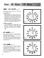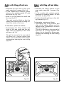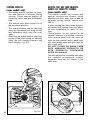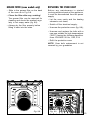
1
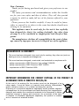
FAN
OVENS
Instruction for the use - Installation advice
KEEP IN A SAFE PLACE
Before operating this oven,
please read these instructions carefully
Dear Customer,
Thank you for having purchased and given your preference to our
product.
The safety precautions and recommendations within this booklet
are for your own safety and that of others. They will also provide
a means by which to make full use of the features offered by your
appliance.
Please preserve this booklet carefully. It may be useful in future,
either to yourself or to others in the event that doubts should arise
relating to its operation.
This appliance must be used only for the task it has explicitly
been designed for, that is for cooking foodstuffs. Any other form
of usage is to be considered as inappropriate and therefore dangerous.
The manufacturer declines all responsibility in the event of damage caused by improper, incorrect or illogical use of the appliance.
DECLARATION OF CE CONFORMITY
– This oven has been designed to be used only for cooking. Any other use (such as
heating a room) is improper and dangerous.
– This oven has been designed, constructed, and marketed in compliance with:
- safety requirements of EEC Directive “Low voltage” 2006/95
- safety requirements of EEC Directive “EMC” 89/336;
- requirements of EEC Directive 93/68.
IMPORTANT INFORMATION FOR CORRECT DISPOSAL OF THE PRODUCT IN
ACCORDANCE WITH EC DIRECTIVE 2002/96/EC.
At the end of its working life, the product must not be disposed of as
urban waste. It must be taken to a special local authority differentiated
waste collection centre or to a dealer providing this service.
Disposing of a household appliance separately avoids possible negative
consequences for the environment and health deriving from inappropriate
disposal and enables the constituent materials to be recovered to obtain
significant savings in energy and resources. As a reminder of the need
to dispose of household appliances separately, the product is marked
with a crossed-out wheeled dustbin.
2
IMPORTANT PRECAUTIONS AND RECOMMENDATIONS
– After having unpacked the appliance, check to ensure that it is not damaged.
If you have any doubts, do not use it and contact the store from where you
purchased it.
– Packing materials (i.e. plastic bags, polystyrene foam, nails, packing straps, etc.)
should not be left around within easy reach of children, as these may cause serious
injuries.
– Do not attempt to modify the technical characteristics of the appliance as it may
become dangerous to use.
– Do not carry out cleaning or maintenance operations on the appliance without having
previously disconnected it from the electric power supply.
– If you should decide not to use this appliance any longer (or decide to substitute an
older model), before disposing of it, it is recommended that it be made inoperative in
an appropriate manner in accordance to health and environmental protection regulations, ensuring in particular that all potentially hazardous parts be made harmless,
especially in relation to children who could play with old appliances.
IMPORTANT PRECAUTIONS AND RECOMMENDATIONS FOR USE OF ELECTRICAL
APPLIANCES
Use of any electrical appliance implies the necessity to follow a series of fundamental
rules. In particular:
– Never touch the appliance with wet hands or feet;
– do not operate the appliance barefooted;
– do not allow children or disabled people to use the appliance without your supervision.
The manufacturer cannot be held responsible for any damages caused by improper,
incorrect or unreasonable use of the appliance.
USING THE OVEN FOR THE FIRST TIME
You are advised to carry out the following operations:
– Assemble the interior of the oven as described under the heading “Cleaning and maintenance”
– Switch the empty oven ON at maximum temperature for about two hours to eliminate
traces of grease and smell from the components.
– Let the oven cool down, switch off the electrical supply, then clean the inside of the
oven with a cloth soaked in water and neutral detergent and dry thoroughly.
3
Control panel
1
4
3
Fig. 1.1
P
A
U
T
O
1(A or B)
5
2
4
3
Fig. 1.2
A
U
T
O
1(A or B)
6-7
2
4
3
Fig. 1.3
1(A or B)
8-9-10
4
2
3
Fig. 1.4
0
10
20
120
110
30
40
100
90
50
80
1(A or B)
A
4
70
60
11-12
B
2
TYPES OF THERMOSTAT
Depending on the models the thermostat
could be of type A (50 to 225°C) or type
B (50 to 250°C)
4
3
1(A or B)
2
4
3
1(A or B)
2
4
3
1(A or B)
2
4
3
1(A or B)
2
Fig. 1.5
P
A
U
T
O
5
Fig. 1.6
A
U
T
O
6-7
Fig. 1.7
8-9-10
Fig. 1.8
55
0
5
50
10
15
45
40
20
35
30
25
11-12
CONTROL PANEL
1.
2.
3.
4.
5.
6.
Oven thermostat knob (type A or B)
Function selector knob
Power on indicator lamp
Oven temperature indicator lamp
Electronic programmer
Electronic clock/end cooking timer
7.
8.
9.
10.
11.
12.
Electronic clock
Clock programmer (start-end)
Electric clock with alarm
Electric clock
Timer (120’ cut-off)
60’ alarm
5
How to use the oven
2
GENERAL FEATURES
OPERATING PRINCIPLES
The heating and cooking in electrical hot
air ovens take place by forced convection.
Heating and cooking in the fan oven are
obtained in the following ways:
The two elements which make this process take place are:
a. by forced convection
A fan sucks in the air contained in the
oven, which circulates it through the
circular heating element and then
forced back into the oven by the fan.
Before the hot air is sucked back
again by the fan to repeat the
described cycle, it envelops the food
in the oven, provoking a complete and
rapid cooking. It is possible to cook
several dishes simultaneously.
- Grill element
- Circular element
2000 W
2200 W
NOTE:
Upon first use, it is advisable to operate
the oven at the maximum temperature
(thermostat knob on the maximum position) for 60 minutes in the position
to eliminate possible traces of grease on
the heating elements.
Repeat the operation for another 15
minutes with the grill element on as
explained in the chapters GRILLING
and USE OF THE GRILL.
b. by radiation
The heat is radiated by the infra red
grill element.
c. by ventilation
The food is defrosted by using the
fan only function without heat.
WARNING:
The door is hot, use the handle.
During use the appliance becomes hot.
Care should be taken to avoid touching
heating elements inside the oven.
GREASE FILTER (some models only)
– A special screen is provided at the
back of the oven to catch grease particles, mainly when meat is being
roasted (see page 23).
– When baking pastry etc. this filter
should be removed.
– Always clean the filter after cooking as
any solid residues on it might adversely affect the oven performance.
6
Fig. 2.1A
Attention: the oven door becomes
very hot during operation.
Keep children away.
THERMOSTAT KNOB
(fig. 2.1A - 2.1B)
To turn on the heating elements of the
oven, set function selector knob to the
required position and the thermostat
knob to the desired temperature.
To set the temperature, turn the thermostat control knob indicator mark to the
required temperature.
The elements will turn on or off automatically which is determined by the thermostat.
The operation of the heating elements is
signalled by a light placed on the control
panel.
FUNCTION SELECTOR KNOB (fig. 2.2)
Rotate the knob clockwise to set the
oven to one of the following functions:
OVEN LIGHT
By turning the function selector knob to
this setting, the oven light will illuminate
in the oven cavity (15W).
The oven light will operate on all selected functions.
DEFROSTING FROZEN FOODS
Only the oven fan is on.
To be used with the thermostat knob in
the off “●” position because the other
positions have no effect.
The defrosting is done by simple ventilation without heat.
Recommended for:
To rapidly defrost frozen foods; 1 kilogram requires about one hour.
The defrosting times vary according to
the quantity and type of foods to be
defrosted.
0
Fig. 2.1B
Fig. 2.2
7
HOT AIR COOKING
The circular element and the fan are on.
The heat is diffused by forced convection and the temperature must be regulated between 50°C and the maximum
position with the thermostat knob.
It is not necessary to preheat the oven.
Recommended for:
For foods that must be well done on the
outside and tender or rare on the inside,
i. e. lasagna, lamb, roast beef, whole
fish, etc.
GRILLING
The infra-red heating element is switched
on. The heat is diffused by radiation.
Use with the oven door closed and the
thermostat knob must be regulated
between 50°C and 200°C max.
For correct use see chapter “USE OF THE
GRILL”.
Recommended for:
Intense grilling action for cooking with the
broiler; browning, crisping, “au gratin”,
toasting, etc.
It is recommended that you do not
grill for longer than 30 minutes at any
one time.
Attention: the oven door becomes
very hot during operation.
Keep children away.
8
COOKING ADVICE
STERILIZATION
Sterilization of foods to be conserved, in
full and hermetically sealed jars, is done
in the following way:
a. Set the switch to position
b. Set the thermostat knob to position
175 °C and preheat the oven.
c. Fill the dripping pan with hot water.
d. Set the jars onto the dripping pan
making sure they do not touch each
other and the door and set the thermostat knob to position 125 °C.
When sterilization has begun, that is,
when the contents of the jars start to
bubble, turn off the oven and let cool.
REGENERATION
Set the switch to position
and the
thermostat knob to position 150° C.
Bread becomes fragrant again if wet with
a few drops of water and put into the
oven for about 10 minutes.
ROASTING
USE OF THE GRILL
To obtain classical roasting, it is necessary to remember:
– that it is advisable to maintain a temperature between 180 and 200 °C.
– that the cooking time depends on the
quantity and the type of foods.
Set the switch to position
and the
thermostat knob between 50°C and
200°C max.
COOKING DIFFERENT DISHES AT
THE SAME TIME
With the function selector in position
, the ventilated oven allows you to cook
different types of food at the same time.
Fish, cakes and meat can be cooked
together without the smells and flavours
mixing.
The only precautions required are the
following:
– The cooking temperatures must be as
close as possible with a maximum difference of 20° - 25°C between the different foods.
– Different dishes must be placed in the
oven at different times according to
the cooking time required for each
one. This type of cooking obviously
provides a considerable saving on
time and energy.
Leave to warm up for approximately 5
minutes with the door closed.
Introduce the food to be cooked, positioning the rack as close to the grill as
possible.
The dripping pan should be placed
under the rack to catch the cooking
juices and fats.
Grilling with the oven door closed.
Grilling with the oven door closed and
do not for longer than 30 minutes at
any one time.
Attention: the oven door becomes
very hot during operation.
Keep children away.
9
Electronic programmer
The electronic programmer is a device
which groups together the following functions:
– 24 hours clock with illuminated display
– Timer (up to 23 hours and 59 minutes)
– Program for automatic oven cooking
– Program for semi-automatic oven
cooking.
3
Description of the illuminated
symbols:
AUTO - flashing - Programmer in automatic position but not programmed
AUTO - illuminated - Programmer in
automatic position with program
inserted.
Automatic cooking taking place
Timer in operation
Description of the buttons:
Timer
Cooking time
End of cooking time
Manual position and cancellation of
the inserted cooking program
or
To increase the numbers on
the digital display
or
To decrease the numbers on
the digital display.
and AUTO - flashing - Program
error.
(The time of day lies between the
calculated cooking start and end
time).
Note:
Select a function by the respective button and, in 5 seconds, set the required
time with the
( ) /
( ) buttons
(“one-hand” operation).
After a power cut the display resets to
zero and cancels the set programs.
P
A
U
T
O
10
Fig. 3.1
Fig. 3.2
ELECTRONIC CLOCK (fig.
3.2)
The programmer is equipped with an
electronic clock with illuminated numbers which indicates hours and minutes.
Upon immediate connection of the oven
or after a power cut, three zeros will
flash on the programmer display.
To set the correct time of day it is necessary to push the
button and then
the
( ) or
( ) button until you
have set the correct time (fig. 3.2).
In another way push simultaneously the
two buttons and at the same time
push the
( ) or
( ) button.
Note: If the clock is reset it deletes any
previously set programs
NORMAL COOKING WITHOUT THE
USE OF THE PROGRAMMER
To manually use the oven, without the
aid of the programmer, it is necessary to
cancel the flashing AUTO by pushing the
button
(AUTO will be switched off
and the symbol
will illuminate - Fig.
3.3).
Attention: If the AUTO is illuminated
(which means a cooking program has
already been inserted), by pushing the
button
you cancel the program and
return to manual operation.
If the oven is switch on, you must
switch off manually.
ELECTRONIC TIMER
The timer program consists only of a
buzzer which may be set for a maximum
period of 23 hours and 59 minutes.
If the AUTO symbol is flashing push the
button.
To set the time, push the
button and
the
( ) or
( ) until you obtain
the desired time in the panel (fig. 3.4).
Having finished the setting, the clock
hour will appear on the panel and the
symbol will be illuminated.
The countdown will start immediately and
may be seen at any moment on the panel
by simply pressing the button
.
At the end of the time, the
symbol
will disappear and the buzzer will sound
and continue for approximatley 7 minutes or until a button is pressed (not the
( )/
( ) buttons). After a short
time the display will revert back to the
time of day.
SETTING THE FREQUENCY OF THE
AUDIBLE SIGNAL
The buzzer has 3 different tones and can
be changed by pressing the
( ) button, but only when the time of day is displayed
A
U
T
O
Fig. 3.3
Fig. 3.4
11
AUTOMATIC OVEN COOKING
To cook food automatically in the oven,
it is necessary to:
1. Set the length of the cooking period
2. Set the end of the cooking time
3. Set the temperature and the oven
cooking program.
These operations are done in the
following way:
1. Set the length of the cooking period
by pushing the
button and the
( ) button to increase, or
( )
to decrease if you have passed the
desired time (fig. 3.5). The AUTO and
the
symbol will illuminate.
2. Set the end of the cooking time by
pressing the
button (the cooking
time already added to the clock time
will appear), and the
( ) button
(fig. 2.6); if you pass the desired time
you may get back by pushing the
( ) button.
After this setting, the
symbol will
disappear. If after this setting, the
AUTO flashes on the display and a
buzzer sounds, it means there was
an error in the programming, that is
that the cooking cycle has been
superimposed on the clock. In this
case, modify the end of cooking time
or the cooking period itself by following again the above mentioned
instructions.
3. Set the temperature and the cooking
program by using the switch and thermostat knobs of the oven (see specific
chapters).
Now the oven is programmed and everything will work automatically, that is the
oven will turn on at the right moment to
end the cooking at the established hour.
During cooking, the
symbol remains
illuminated.
By pushing the
button you can see
the time that remains until the end of
cooking.
The cooking program may be cancelled at any time by pushing
.
At the end of the cooking time the oven
will turn off automatically, the
symbol
will turn off, AUTO will flash and a buzzer will be sound, which can be turned
off by pushing any of the buttons except
the
( ) /
( ) buttons.
Turn the switch and thermostat knobs to
zero and put the programmer onto “manual” by pressing the
button.
Attention: After a power cut the clock
resets to zero and cancels the set programs.
After a power cut, three zeros will flash
on the display.
P
P
A
U
T
O
12
Fig. 3.5
A
U
T
O
Fig. 3.6
SEMI - AUTOMATIC COOKING
This is used to automatically switch off
the oven after the desired cooking period has elapsed.
Set the length of the cooking period by
pushing the
button and the
( )
button to increase, or
( ) to
decrease if you have passed the desired
time (Fig. 3.7).
At the end of the cooking period, the oven
and the
symbol will disappear, AUTO
will flash and a buzzer will sound and can
be stopped by pushing any of the buttons
except the
( ) /
( ) buttons.
Turn the function selector switch and
thermostat knobs to zero and put the
programmer onto “manual” by pressing
the
button.
AUTO and the
symbol will be illuminated.
Then set the temperature and the cooking program using the function selector
switch and thermostat knobs (see specific chapters).
The oven is switched on and it will be
switched of automatically at the end of
the desired time.
During cooking, the
symbol remains
illuminated and by pressing the button
you can see the remaining cooking
time..
The cooking program can be cancelled at any time by pushing the
button.
P
A
U
T
O
Fig. 3.7
P
A
U
T
O
Fig. 3.8
13
Electronic clock/end cooking timer
The electronic programmer is a device
with the following functions:
– 24 hours clock with illuminated
display
– Timing of oven cooking with automatic
switch-off (max. 99 minutes).
ELECTRONIC CLOCK
Upon immediate connection of the oven
or after a mains failure, three zeros will
flash on the programmer panel.
To set the clock it is necessary to push
the
button and then, within 7 seconds,
the
or
button until you have set the
correct time.
The clock will show zero after a mains
failure.
Attention: When the programmer
display shows three flashing zeros the
oven cannot be switched on.
The oven can be switched on when the
symbol
is shown in the display.
SETTING THE FREQUENCY OF THE
ALARM SOUND
The selection from 3 possibilities of
sound can be made by pressing the
button.
4
COOKING WITH AUTOMATIC
SWITCH-OFF
The aim of this function is to
automatically stop the cooking after a pre
programmed time, for a maximum period
of 99 minutes.
To set the cooking time, push the
or
button until you obtain the desired
time in the display. The symbol AUTO
will be shown in the display. Then you
adjust the oven thermostat knob
according to the required temperature.
The oven will immediately start to
operate and will work for the pre
programmed time. The display shows the
count down. Clock time can be displayed
by pressing the
button. Once the time
has elasped, the oven will switch off
automatically, the symbol AUTO will go
off and an intermittent buzzer, lasting 7
minutes, will start; this can be stopped by
pressing the
button.
Important: Before the buzzer is stopped
switch off the oven manually.
To cancel the cooking program at any
time press the
and
buttons
together and release the
button first.
ELECTRONIC ALARM
A
U
T
O
Fig. 4.1
14
The programmer can be used as an
alarm only for a maximum period of 99
minutes.
To set the alarm, push the
or
button until you obtain the desired time
in the display. Once the time has
elasped, an intermittent buzzer, lasting 7
minutes, will start; this can be stopped
by pressing the
button.
Attention: If the bottom oven is
switched on when the buzzer starts, it
will be automatically switched off. For it
to operate furtherly you have to stop the
buzzer by pressing the
button.
Electronic clock
ELECTRONIC CLOCK
(fig. 5.1)
The electronic alarm is a device which
groups the functions of 24 hours clock
with illuminated display and 99 minutes
alarm.
Upon immediate connection of the oven
or after a blackout, three zeros will flash
on the programmer panel.
To set the hour it is necessary to push
the
button and then, within 7 seconds, the
or
button until you have
set the exact hour.
An energy black-out makes the clock
go to zero.
5
ELECTRONIC ALARM
The alarm program consists only of a
buzzer which may be set for a maximum
period of 99 minutes.
To set the time, push the
or
until
you obtain the desired time in the panel.
Having finished the setting, the
symbol will be lighted and the countdown will
start immediately. At the end of the time,
the
symbol will be switched off and
an intermittent buzzer, during 7 minutes,
will go off; this can be stopped by pressing the
buttons.
To stop the alarm countdown in any
moment press the
and
buttons
together and release the
button first.
SETTING THE FREQUENCY OF THE ALARM
SOUND
The selection from 3 possibilities of
sound can be made by pressing the
button.
Fig. 5.1
15
Clock programmer
The clock programmer is a device which
groups together the following functions:
– Electric clock
– Timing of oven cooking with automatic
switch-off (max. 180 minutes).
– End cooking buzzer
SETTING THE TIME
To adjust, simply press the knob “A” (fig.
6.1) and rotate anticlockwise to the correct time.
MANUAL COOKING (without programmer)
To use the oven without the programmer, i.e. only with the function selector/
thermostat, the programmer function
must be cancelled by rotating knob “A”
anticlockwise until the symbol
in window “B” coincides with the indicator (Fig.
6.1).
6
COOKING WITH AUTOMATIC SWITCH-OFF
– Turn on the oven by setting the switch
knob on the desired program and the
thermostat knob onto the desired temperature (see specific chapters).
– Set the cooking time by rotating knob
“A” anticlockwise until desired time in
window “B” coincides with the indicator (Fig. 6.2).
The oven will immediately start to operate and will work for the pre programmed time. Once the time has
elasped, the oven will switch off automatically and an intermittent buzzer will
start; this can be stopped by rotating
knob “A” until the symbol
in window
“B” coincides with the indicator (Fig.
6.3).
Turn the switch and thermostat knobs to
“off” position.
B
A
Fig. 6.2
B
B
A
16
Fig. 6.1
Fig. 6.3
A
Electric clock with alarm - Electric clock 7
ELECTRIC CLOCK WITH ALARM
(Fig. 7.1)
To adjust the clock, press knob “A” and
turn clockwise until it shows the correct
time.
Caution: the knob “A” will become loose
if turned anticlockwise.
ELECTRIC CLOCK
(Fig. 7.2)
To adjust the clock, press knob “A” and
turn clockwise until it shows the correct
time.
Caution: the knob “A” will become loose
if turned anticlockwise.
MINUTE COUNTER
The minute counter function consists
simply of an acoustic signal which
comes on once the set time has
elapsed.
To set the minute counter, rotate the
small knob (A) clockwise or anticlockwise (without pressing it) until the hand
(C) coincides with the required time
(max 55 minutes) (Fig. 7.1).
Countdown will begin immediately and
the hand (C) will begin to turn anticlockwise, always showing the remaining
time.
Once the set time has elapsed the bell
will ring until the hand (C) is positioned
to the symbol
by rotating the knob
(A) anticlockwise.
C
A
A
Fig. 7.1
Fig. 7.2
17
Timer - 60’ Alarm - 120’ Alarm
TIMER - 120’ CUT-OFF
8
(fig. 8.1)
The function of the timer runs the oven
for a preset time.
1) Starting up.
After setting the function selector and
thermostat to the required mode and
temperature, rotate the timer knob
clockwise until you reach the required
cooking time (max 120 minutes).
Once this time has elapsed, the timer
will return to the “0” position and the
oven will automatically switch off.
0
10
20
120
110
30
100
40
90
Fig.
Fig. 8.1
9.1
2) Manual position.
If the cooking time is longer than two
hours or if you wish to use the oven
manually, switching it off as required,
the knob must be turned to position
.
50
80
55
70
0
60
5
50
60’ ALARM
(fig. 8.2)
The minute counter is a timed acoustic
warning device which can be set for a
maximum of 60 minutes.
The knob must be rotated clockwise as
far as the 60 minute position and then
set to the required time by rotating it
anticlockwise.
120’ ALARM
40
Fig.
Fig. 8.2
9.2
20
35
110
30
0
25
10
100
20
30
90
80
40
70
Fig. 8.3
18
15
45
(fig. 8.3)
The minute counter is a timed acoustic
warning device which can be set for a
maximum of 120 minutes.
The knob must be rotated clockwise as
far as the 120 minute position and then
set to the required time by rotating it
anticlockwise.
10
60
50
Cleaning and maintenance
GENERAL ADVICE
Important:
Before any operation of cleaning and
maintenance disconnect the appliance from the electrical supply.
It is advisable to clean when the
appliance is cold and especially for
cleaning the enamelled parts.
Avoid leaving alcaline or acidic substances (lemon juice, vinegar, etc.) on
the surfaces.
Avoid using cleaning products with a
chlorine or acidic base.
The oven must always be cleaned after
every use, using suitable products and
keeping in mind that its operation for 30
minutes on the highest temperature
eliminates most grime reducing it to
ashes.
9
STAINLESS STEEL AND ALUMINIUM
PARTS AND SILK-SCREEN PRINTED
SURFACES
Clean using an appropriate product.
Always dry thoroughly.
IMPORTANT: these parts must be
cleaned very carefully to avoid scratching
and abrasion. You are advised to use a
soft cloth and neutral soap.
ENAMELLED PARTS
All the enamelled parts must be cleaned
with a sponge and soapy water only or
other non-abrasive products.
Dry preferably with a chamois leather.
STAINLESS STEEL SURFACES WITH
ANTI-FINGERPRINT TREATMENT
CAUTION:
The stainless steel surfaces used in
some ovens are protected with a Special
Lacquer to reduce finger-print marks.
To avoid damaging this lacquer, do not
clean the stainless steel with abrasive
cleaners or abrasive cloths or scouring
pads.
ONLY SOAP/WARM WATER MUST BE
USED TO CLEAN THE STAINLESS
STEEL SURFACES.
Do not use a steam cleaner because
the moisture can get into the
appliance thus make it unsafe.
INSIDE OF OVEN
The oven must be always cleaned after
every use, using suitable products and
keeping in mind that its operation for 30
minutes on the highest temperature
eliminates most grime reducing it to
ashes.
Do not store flammable material in
the oven.
19
OVEN FITTING OUT
Models with embossed cavity
The oven shelves are provided with a
security block to prevent accidental
extraction.
They must be inserted operating as per
figure 9.1.
To pull them out operate in the inverse
order.
Models with wire racks
– Assemble the wire racks to the oven
walls using the 2 screws (Fig. 9.2).
– In the models with catalytic panels
interpose the catalytic panels “A” with
the arrow up (Fig. 9.2).
– Slide in, on the guides, the shelf and
the tray (fig. 9.3).
The shelf must be fitted so that the
safety catch, which stops it sliding out,
faces the inside of the oven.
– To dismantle, operate in reverse order.
Fig. 9.1
A
Fig. 9.2
20
Fig. 9.3
Models with tilting grill and wire
racks
Models with tilting grill and sliding
shelves
– Assemble the wire racks on the oven
walls using the 2 screws (Fig. 9.4).
– In the models with catalytic panels
interpose the catalytic panels “A” with
the arrow up (Fig. 9.4).
– Slide in, on the guides, the shelf and
the tray (fig. 9.3).
The rack must be fitted so that the
safety catch, which stops it sliding out,
faces the inside of the oven.
– Assemble the sliding shelves on the
oven walls using the 2 screws (Fig.
9.6).
– In the models with catalytic panels
interpose the catalytic panels “A” with
the arrow up (Fig. 9.6).
– Position the shelf and tray on the sliding shelves (fig. 9.7).
To dismantle, operate as follows:
– Unscrewing the fixing screws and
slide off the wire racks and the catalytic liners (if supplied) to the oven
wall as in fig. 9.4.
The grill is secured to the rear wall of
the oven on a hinge system that
allows it to be lowered to allow proper
access when cleaning the oven ceiling
(fig. 9.5).
A
To dismantle, operate as follows:
– Unscrewing the fixing screws and
slide off the sliding shelves and the
catalytic liners (if supplied) to the oven
wall as in fig. 9.6.
The grill is secured to the rear wall of
the oven on a hinge system that
allows it to be lowered to allow proper
access when cleaning the oven ceiling
(fig. 9.5).
A
Fig. 9.4
Fig. 9.5
21
SLIDING SHELVES
(some models only)
– The sliding shelves facilitate the insertion and removal of shelves during
cooking. These shelves support all
accessory trays and are dishwasher
safe.
– The shelves stop when pulled out to
the maximum position.
– The sliding shelves can be removed
easily by unscrewing the fixing screws
and detaching them from the oven
walls.
– Removing the sliding shelves improves
access to the oven ceiling for cleaning
(after the grill heating element has
been lowered - fig. 9.5).
ADVICE FOR USE AND MAINTENANCE OF CATALYTIC PANELS
(some models only)
The catalytic panels are covered with
special microporous enamel which
absorbs and does away with oil and fat
splashes during normal baking over
200°C.
If, after cooking very fatty foods, the panels remain dirty, operate the oven “idling”
on max temperature for about 30 minutes.
These panels do not require to be
cleaned, however it is advised to periodically remove them from the oven (at
least the side panels) and to wash them
with tepid soapy water and then wipe off
with a soft cloth.
DO NOT CLEAN OR WASH THEM
WITH ABRASIVE PRODUCTS OR
WITH PRODUCTS CONTAINING
ACIDS OR ALKALIS.
The side panels are reversible and when
the catalytic microporous enamel
degrades, they can be turned to the
other side.
A
22
A
Fig. 9.6
Fig. 9.7
GREASE FILTER (some models only)
REPLACING THE OVEN LIGHT
– Slide in the grease filter on the back
of the oven as in Fig. 9.8.
Before any maintenance is started
involving electrical parts of the appliance,
it must be disconnected from the power
supply.
– Clean the filter after any cooking!
The grease filter can be removed for
cleaning and should be washed regularly in hot soapy water (fig. 9.8).
– Always dry the filter properly before
fitting it back into the oven.
– Let the oven cavity and the heating
elements cool down;
– Switch off the electrical supply;
– Unscrew the protective cover (fig. 9.9);
– Unscrew and replace the bulb with a
new one suitable for high temperatures
(300°C) having the following specifications: 230-240V 50 Hz, 15W, E14
– Refit the protective cover
NOTE: Oven bulb replacement is not
covered by your guarantee
2
Fig. 9.8
Fig. 9.9
1
23
REMOVING THE OVEN DOOR
The oven door can easily be removed as
follows:
– Open the door to the full extent (fig.
9.10a).
– Open the lever “A” completely on the
left and right hinges (fig. 9.10b).
– Hold the door as shown in fig. 9.10.
Fig. 9.10a
– Gently close the door (fig. 9.10) until
left and right hinge levers “A” are
hooked to part “B” of the door (fig.
9.10b)
A
– Withdraw the hinge hooks from their
location following arrow “C” (fig.
9.10d).
B
– Rest the door on a soft surface.
– To replace the door, repeat the above
steps in reverse order.
Fig. 9.10b
Do not use harsh abrasive cleaners
or sharp metal scrapers to clean
the oven door glass since they can
scratch the surface, which may
result in shattering of the glass.
Fig. 9.10c
C
24
Fig. 9.10
Fig. 9.10d
Advice
for the
installer
25
Installation
10
IMPORTANT
50
– The appliance should be installed by a
QUALIFIED INSTALLATION TECHNICIAN.
The appliance must be installed in compliance with regulations in force.
560
585
The oven can be fitted in standard units,
width and depth 60 cm.
Installation requires a compartment as
illustrated in figures 10.1 and 10.2.
On the lover side, the oven must lay on
supports standing the oven weight.
The 4 screws serve as fixing.
Fig. 10.1
560
591
555
594
in
0m
55
0
54
594
26
20
Fig. 10.2
50 mm
;
;
600
;;
30 mm
Fig. 10.3
50
550
Fig. 10.4
To ensure internal ventilation, aeration channels must be provided as illustrated in the
figures 10.3 and 10.4.
The walls surrounding the oven must be made of heat-resistant material.
Taking care NOT to lift the oven by the door handle.
27
OVEN DOOR
LOWER TRIM
AIR FLOW
Fig. 10.5
IMPORTANT:
To avoid damage to the lower trim please note the following instructions.
The lower trim is designed to allow for good air circulation and the correct opening of
the oven door.
To ensure the trim is not damaged due to the appliance being placed on the floor, the
appliance should be suitably supported as in above illustrations.
After installation the appliance door should be slowly opened to ensure no damage has
occurred.
No responsibility for lower trim damage will be accepted if these instructions have
not been followed.
28
Electrical section
Before effecting any intervention
on the electrical parts the appliance must be disconnected from
the network.
GENERAL
– The connection to the electrical network
must be carried out by qualified personnel and must be according to existing
norms.
– The appliance must be connected to the
electrical network verifying above all that
the voltage corresponds to the value
indicated on the specifications plate and
that the cables section of the electrical
plant can bear the load which is also
indicated on the plate.
– If the appliance is supplied without a
power supply plug and if you are not
connecting directly to the mains, a standardized plug suitable for the load must
be fitted.
– The colours of the wires in the appliance power cable may not correspond
with the colours marked on the terminals of your electrical plug. The plug
should always be wired as follows:
● connect the green/yellow wire to the
terminal marked with the letter E or
the earth symbol or coloured
green/yellow;
● connect the blue wire to the terminal
marked with the letter N or coloured
black;
● connect the brown wire to the terminal marked with the letter L or
coloured red.
11
– The bi-polar plug must be connected to
an outlet connected to the grounding
unit in conformity to security norms.
– If the oven is to be connected directly to
the mains, it must be placed with an
omnipolar switch with minimum opening
between the contacts of 3 mm between
the appliance and the mains.
– The power supply cable must not touch
the hot parts and must be positioned so
that it does not exceed 75°C at any
point.
– Once the oven has been installed, the
switch or socket must always be accessible.
– If the power supply cable is damaged it
must be substituted by a suitable cable
available in the after sales service.
N.B. For connection to the mains, do
not use adapters, reducers or branching devices as they can cause overheating and burning.
If the installation requires alterations to
the domestic electrical system call an
expert.
He should also check that the socket
cable section is suitable for the power
absorbed by the appliance.
The connection of the appliance to
the grounding unit is mandatory.
The manufacturer declines every
responsability for any inconvenience resulting from the inobservance of this condition.
29
CONNECTION OF THE POWER SUPPLY CABLE
Unhook the terminal board cover by
inserting a screwdriver into the two
hooks “A” (fig. 11.1).
Open the cable gland by unscrewing
screw “F” (fig. 11.2), unscrew the terminal screws and remove the cable.
The new supply cable, of suitable type
and section, is connected to the terminal
board following the diagram fig. 11.3.
FEEDER CABLE SECTION TYPE HO5RR-F
230 V
3 x 1,5 mm2
F
Fig. 11.2
230 V
L1
N (L 2)
PE
A
Fig. 11.1
30
Fig. 11.3
31
Descriptions and illustrations in this booklet are given as simply indicative.
The manufacturer reserves the right, considering the characteristics of the models described here, at any time
and without notice, to make eventual necessary modifications for their construction or for commercial needs.
cod. 1102113
ß6