1
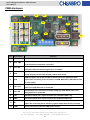
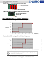
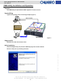
Chassis Management Board User’s Manual 80H11313101A1 CHENBRO Chassis Management Board User’s Manual July / 7 / 2009 15Fl., No.150, Jian Yi Road, Chung Ho City, Taipei Hsien, Taiwan R.O.C., Tel: +886 2 82265500 Fax: +886 2 82265392 Email: [email protected] 1 w w w . c h e n b r o . c o m 80H11313101A1 Chassis Management Board User’s Manual 80H11313101A1 Copyright Copyright © 2008 CHENBRO Micom Co., Ltd.. All rights reserved. Unless otherwise indicated, all materials in this manual are copyrighted by CHENBRO Micom Co., Ltd.. All rights reserved. No part of this manual, either text or image may be used for any purpose other than internal use within purchasing company. Therefore, reproduction, modification in any form or by any means, electronic, mechanical or otherwise, for reasons other than internal use, is strictly prohibited without prior written permission. CHENBRO Micom Co., Ltd. reserves the right to make improvement and modification to the products indicated in this manual at any time. Specifications are therefore subject to change without prior notice. Information provided in this manual is intended to be accurate and reliable. However, CHENBRO Micom Co., Ltd., assumes no responsibility for its use, nor for any infringements upon the rights of third parties, which may result from its use. Trademark All registered and unregistered trademarks and company names contained in this manual are property of their respective owners including. Technical Support CHENBRO works hard to offer our customers maximum performance from our chassis. But in case you have any problem with our product you can find supports from the following resources. Web Support Detail information of our products is in our website. You can find technical updates, installation guides, FAQs, technical specifications and more. Our web address is: www.chenbro.com. You can also fill out the technical support form at our Technical Support page. You technical issue inquiries will be sent directly to our support professionals. Phone Support You can also contact CHENBRO HQ or branch office for immediate support; their contact Information is as following: CHENBRO HQ CHENBRO Europe B.V. CHENBRO Micom (USA) Inc. Tel: 886-2-8226-5500 Tel: 31-40-295-2045 Tel: 1-909-947-3200 Fax: 886-2-8226-5423 Fax: 31-40-295-2044 Fax : 1-909-947-4300 15Fl., No.150, Jian Yi Road, Chung Ho City, Taipei Hsien, Taiwan R.O.C., Tel: +886 2 82265500 Fax: +886 2 82265392 Email: [email protected] 2 w w w . c h e n b r o . c o m Email Support Chassis Management Board User’s Manual 80H11313101A1 Contents 15Fl., No.150, Jian Yi Road, Chung Ho City, Taipei Hsien, Taiwan R.O.C., Tel: +886 2 82265500 Fax: +886 2 82265392 Email: [email protected] 3 w w w . c h e n b r o . c o m Copyright..................................................................................................................................................... 2 Trademark ................................................................................................................................................... 2 Technical Support..................................................................................................................................... 2 Contents ...................................................................................................................................................... 3 Revision History........................................................................................................................................ 4 Safety Information .................................................................................................................................... 5 Conventions Used in this Manual......................................................................................................... 5 Introduction ................................................................................................................................................ 5 About this Guide ............................................................................................................................... 5 Introducing Chenbro Chassis Management Board (CMB) .................................................... 5 CMB Hardware ........................................................................................................................................... 6 Function Switch Pin Definition (SW1) ......................................................................................... 7 System Failure & Alarm Mute Signal Pin Header (CN3) ......................................................... 8 CMB to M/B RS-232 or USB mode connecting selection (JP2) ............................................ 8 Fan PWM Duty Cycle v.s System Temperature................................................................................. 8 Function Switch DIP8 Setting at On for 55°C Alarm Temperature....................................... 8 Function Switch DIP8 Setting at Off for 65°C Alarm Temperature....................................... 8 CMB Utility Installation and Operation................................................................................................ 9 Purpose ............................................................................................................................................... 9 System Wiring.................................................................................................................................... 9 Supported OS..................................................................................................................................... 9 Utility Installation .............................................................................................................................. 9 Main operation window ................................................................................................................. 11 System Connection Relative Information......................................................................... 12 Scroll Function Menu............................................................................................................. 12 System Current Device Information................................................................................... 13 Status and Alarm Monitoring Pages .................................................................................. 14 Change the Logo............................................................................................................................. 17 Cabling Example ..................................................................................................................................... 18 Chassis Management Board User’s Manual 80H11313101A1 Revision History Date Modifications July / 7 / 2009 z First Release w w w . c h e n b r o . c o m 15Fl., No.150, Jian Yi Road, Chung Ho City, Taipei Hsien, Taiwan R.O.C., Tel: +886 2 82265500 Fax: +886 2 82265392 Email: [email protected] 4 Chassis Management Board User’s Manual 80H11313101A1 Safety Information z Read the installation instructions before connecting to the power source. z Only trained and qualified personnel should be allowed to install, replace or service this equipment. z Never install this product in a wet environment. z Position system cables and power cables carefully; route system cable and the power cable and plug so that they cannot be stepped on or tripped over. Be sure that nothing rests on your system component cables or power cable. Conventions Used in this Manual The following conventions are used in this manual. Important Icon: Provides important information on the current topic that must not be overlooked. Introduction About this Guide This Chassis Management Board (CMB) user’s manual provides the information for functions, capabilities, configuring and using of fan control in chassis. Introducing Chenbro Chassis Management Board (CMB) 15Fl., No.150, Jian Yi Road, Chung Ho City, Taipei Hsien, Taiwan R.O.C., Tel: +886 2 82265500 Fax: +886 2 82265392 Email: [email protected] 5 w w w . c h e n b r o . c o m Chenbro CMB provides a convenient way for fan, PSU and system temperature monitoring in chassis. Via the software utility, system manager can monitor the status in operation center. The function of CMB includes fan PWM control, fan failure, system overheat, PSU failure alarm and alarm mute. Chassis Management Board User’s Manual 80H11313101A1 CMB Hardware 12 5 13 15 14 16 7 6 A 8 9 18 B 11 10 17 1 2 4 3 No. Description 1 SW1 2 CN1, CN2 3 JT1, JT2 4 CN3 Function DIP1~10 function setup for Fan control, temperature detection or PWM control Standard 4-pin power connectors. When using up to 6x fans, it is recommended to have all power connectors connected. Reference thermal sensor pin headers. Must have 2 thermal couple wires connection when fan monitoring function is enabled. System failure & alarm mute signal pin headers (connecting to chassis LED board). Pin[1-2] = alarm LED; Pin[5-6] = alarm mute switch PWM fan bypass pin header for M/B on-board fan control. Specified cable CN6 required for connecting to fan connectors on M/B. Meanwhile, SW1-DIP9 should be set to [OFF] Group-A 8-pin fan connectors (for 8P8C double-deck fans only). SW1-DIP10 6 JA1~JA6 7 JF1~JF6 8 JP1 PSU failure alarm (TTL) signal connector (for redundant PSU only) 9 JM1 PSU failure alarm mute signal connector (for redundant PSU only) 10 B1 11 LED1 must set to [ON] when fan is connected Group-B 4-pin fan connectors (for 4P4C / 3P3C fan). SW1-DIP10 must set to [OFF] when fan is connected Buzzer continually alarm indicating system fan failure Buzzer dis-continually alarm indicating system temperature failure (overheat) Green LED blinking indicates CMB works normal 15Fl., No.150, Jian Yi Road, Chung Ho City, Taipei Hsien, Taiwan R.O.C., Tel: +886 2 82265500 Fax: +886 2 82265392 Email: [email protected] 6 w w w . c h e n b r o . c o m 5 Chassis Management Board User’s Manual 80H11313101A1 RS-232 (COM port) for M/B and CMB communication. RS-232 cable is required 12 CN9 13 CN7 14 JP2 15 JP3 Function Reserved for I2C function selection 16 CN4 Function Reserved for factory programming 17 CN5 External USB connector, the JP2 must be set to [2-3] closed. 18 CN8 Function Reserved for I2C connection when using CMB utility. Meanwhile the JP2 must be set to [1-2] closed. Function reserved for factory programming CMB to M/B RS-232 or USB mode connecting selection Pin[1-2] = RS-232 (COM Port), Pin[2-3] = USB Not support mixed fan connection on Group‐A and ‐B at same time. Function Switch Pin Definition (SW1) DIP 1~6 DIP 7 DIP 8 DIP 9 DIP 10 ON Temperature Fan1~6 Monitoring detecting by JT1 & Enable independently JT2 Enable Support 8-pin Alarm Temperature PWM controlled by connector fans is 55°C CMB (Group-A) OFF Temperature Fan1~6 Monitoring detecting by JT1 & Disable independently JT2 Disable Alarm Temperature PWM controlled by Support 4-pin connector fans is 65°C motherboard (Group-B) z DIP1~DIP6: Fan 1~6 monitoring enable [ON] / disable [OFF] When it’s enabled, the thermal sensors must be connected to [JT1 & 2] The fan quantity and SW1 setting enabled must be mapped When all fans monitoring set to [OFF], the fans will run as non-PWM mode without any alarm function No matter PWM or non-PWM fan is connected, the fan monitoring function is enabled when DIP1~6 is set to “ON” position. When it’s enabled, the thermal sensors must be connected to [JT1 & 2] When any fan monitoring is enabled, this DIP7 should be set to enabled at same time When it’s disabled, the fans will run as non-PWM mode z DIP8: alarm temperature setting by 55°C [ON] / 65°C [OFF] z DIP9: PWM control source mode selection. Local CMB [ON] / Motherboard on-board fan connector [OFF] z DIP10: Fan group selection. Group-A [ON] / Group-B [OFF]. DIP10 must be set at correct position, otherwise the fan will run as non-PWM. 15Fl., No.150, Jian Yi Road, Chung Ho City, Taipei Hsien, Taiwan R.O.C., Tel: +886 2 82265500 Fax: +886 2 82265392 Email: [email protected] 7 w w w . c h e n b r o . c o m z DIP7: temperature monitoring enable [ON] / disable [OFF] Chassis Management Board User’s Manual 80H11313101A1 System Failure & Alarm Mute Signal Pin Header (CN3) Pin[1‐2] : Alarm LED Pin[5‐6] : Alarm Mute Switch CMB to M/B RS-232 or USB mode connecting selection (JP2) Pin[1‐2] : RS‐232 (COM Port) Pin[2‐3] : USB Pin 1 Fan PWM Duty Cycle v.s System Temperature Function Switch DIP8 Setting at On for 55°C Alarm Temperature 100% 90% 80% Duty Cycle 70% 60% 50% 40% 20 30 40 50 60 70 80 Temperature °C Function Switch DIP8 Setting at Off for 65°C Alarm Temperature 100% 80% Duty Cycle 70% 60% 50% 40% 20 30 40 50 60 70 80 Temperature °C Apply 2 thermal couple on JT1 & JT2 and set DIP7 to ON enabling the temperature monitoring function 15Fl., No.150, Jian Yi Road, Chung Ho City, Taipei Hsien, Taiwan R.O.C., Tel: +886 2 82265500 Fax: +886 2 82265392 Email: [email protected] 8 w w w . c h e n b r o . c o m 90% Chassis Management Board User’s Manual 80H11313101A1 CMB Utility Installation and Operation Purpose The CMB Utility is required when CMB is applied in Chenbro chassis. System Wiring Typical wiring please refers to following example (Figure-1). Ethernet (UDP) Remote Host LAN Port RAID Card Motherboard PSU GUI Operation (Windows Base) COM Port FAN HDD HDD CMB I2C Board Local Operation RM31408 Figure-1 Supported OS Windows XP / 2000 / Server 2003 / Vista Utility Installation Download zipped utility file (Chenbro CMB Utility.zip) from Chenbro website. Execute “Setup.exe” by following indication. w w w . c h e n b r o . c o m 15Fl., No.150, Jian Yi Road, Chung Ho City, Taipei Hsien, Taiwan R.O.C., Tel: +886 2 82265500 Fax: +886 2 82265392 Email: [email protected] 9 Chassis Management Board User’s Manual 80H11313101A1 w w w . c h e n b r o . c o m 15Fl., No.150, Jian Yi Road, Chung Ho City, Taipei Hsien, Taiwan R.O.C., Tel: +886 2 82265500 Fax: +886 2 82265392 Email: [email protected] 10 Chassis Management Board User’s Manual 80H11313101A1 When setup completed, there will be a group (Chenbro CMB) and shortcut generated in the Windows start-up menu. User can verify a new device “Megawin USB” in the “COM / LPT” of device manager. Figure-2 This utility will be operated as windows register program, a small icon will be Shown on the tooling bar when minimize the operation window. Main operation window System Connection Relative Information There are two sub-pages for different function. w w w . c h e n b r o . c o m Status and Alarm Monitoring Pages Figure-3 System Current Device information Area 15Fl., No.150, Jian Yi Road, Chung Ho City, Taipei Hsien, Taiwan R.O.C., Tel: +886 2 82265500 Fax: +886 2 82265392 Email: [email protected] 11 Chassis Management Board User’s Manual 80H11313101A1 System Connection Relative Information This area shows the main information of connected systems, which includes: z Operation Duration: This presents CMB utility program is been executed after properly connection with M/B z Local or Remote Mode: The local mode is used when the CMB is connected via COM port to the M/B in the same chassis. The remote mode is used for a stand-alone server connect to an extension chassis which has CMB installed. Normally the remote mode is base on USB connection z System time: This shows the target execution of the system clock. z Device list: There are up to 6x system (CMB) can be monitored at one time. Factory default setting is start from system1, and normally to be the server with CMB integrated. For the system2~6, it’s normally runs as “remote” mode, see Figure-4 for the connection concept. Ethernet (UDP) Local Host RM31408 Remote Host M/B USB CMB USB JBOD #1 CMB USB JBOD #2 CMB USB JBOD #3 CMB USB JBOD #4 CMB USB JBOD #5 Figure-4 There are several function on the menu and allow customer to use depends on real operation requirement for remote management via Ethernet (UDP). z Protection Mode: This setting is operated base on preventing any improper access from remote server. However, the protection enable / disable only can be set in local mode, not the remote mode. When the protection mode is enabled, only local mode access and control is allowed. (See Figure-5) 15Fl., No.150, Jian Yi Road, Chung Ho City, Taipei Hsien, Taiwan R.O.C., Tel: +886 2 82265500 Fax: +886 2 82265392 Email: [email protected] 12 w w w . c h e n b r o . c o m Scroll Function Menu Chassis Management Board User’s Manual 80H11313101A1 Figure-5 z Remote Login: This is for host server to access the external chassis (ex. JBOD) with integrated CMB, monitor and control the CMB via Ethernet base on UDP. When execute the remote monitoring, the Ethernet networking information should be checked before a pop-up login window. Meanwhile, the password is required for accessing (See Figure-6). Figure-6 z Change Password: This is for the protection mode password change, only base on “local mode” administration. System Current Device Information This area provides the user-define information input which includes System Name, M/B model, RPS model, and connection COM port. User can save the data as a file. The COM port selection should be checked the device manager after utility is installed and executed. Only the COM port is set properly, the connection between CMB and M/B can be established. 15Fl., No.150, Jian Yi Road, Chung Ho City, Taipei Hsien, Taiwan R.O.C., Tel: +886 2 82265500 Fax: +886 2 82265392 Email: [email protected] 13 w w w . c h e n b r o . c o m Default password: chenbro Chassis Management Board User’s Manual 80H11313101A1 Status and Alarm Monitoring Pages This area includes the major information of environment status and alarm information. z Status: This page include the monitoring of “Fan status”, “Temperature status”, SW1 “Switch setting”, and CMB “Link status”. Fan monitoring: when PWM fan(s) connected, the RPM and PWM (%) mode will be detected and shown on the relative column. (See Figure-7 a.) Fan Group-A or -B will be automatically detected, and the default setting is Group-A. (See Figure-7 b.) According to Group-A application, the bottom group is only activated when 8P8C “double-deck fan” is connected. When the SW1-DIP1~6 is set to “OFF”, all the columns of fan status will show “NA”. (See Figure-8) b. a. Figure-7 w w w . c h e n b r o . c o m Bottom Group Figure-8 15Fl., No.150, Jian Yi Road, Chung Ho City, Taipei Hsien, Taiwan R.O.C., Tel: +886 2 82265500 Fax: +886 2 82265392 Email: [email protected] 14 Chassis Management Board User’s Manual 80H11313101A1 Temperature monitoring: this area shows the real environment temperature when the thermal sensors are connected and SW1-DIP7 is set to “ON” position. (Showing “NA” when DIP7 set to “OFF”, see Figure-9 a.). The threshold shows the definition of alarm temperature. It’s automatically detected according to DIP8. When the thermal sensor is not connected, the fan monitoring function will be disabled automatically or PWM fan runs up to 100% mode. (See Figure-9 b.) a. b. c. d. e. Figure-9 SW1 status: this shows the setting position of SW1 DIP1~10 on CMB. (See Figure-9 c.) Figure-9 d. shows the function description of SW1. Link Status: When a CMB is connected to M/B via COM port with this CMB utility operation, a message will show “Connected”, and message “Polling” shows every 3 seconds to check the linking status. (See Figure-9 e.) If there is no cable connection, this status will show “Disconnected”, and all the monitoring function is disabled. (See Figure-10) w w w . c h e n b r o . c o m Figure-10 15Fl., No.150, Jian Yi Road, Chung Ho City, Taipei Hsien, Taiwan R.O.C., Tel: +886 2 82265500 Fax: +886 2 82265392 Email: [email protected] 15 Chassis Management Board User’s Manual 80H11313101A1 z Alarm Notification: This page shows all the monitored devices status. When any alarm is triggered, the relative column will change to corresponding messages and defined colors. If user mute the buzzer via alarm mute switch at front control panel (connected to CN3), the failure LED will remain enabled until alarm event is fixed. Figure-11 shows the failure status with alarm mute triggered. The redundant PSU failure only be enabled when PSU module failed or un-installed. It’s not support the voltage monitoring. Figure-11 Alarm (Pop-up) Window: When any alarm event is triggered, a pop-up window (see Figure-12) is shown to notify administrator. 15Fl., No.150, Jian Yi Road, Chung Ho City, Taipei Hsien, Taiwan R.O.C., Tel: +886 2 82265500 Fax: +886 2 82265392 Email: [email protected] 16 w w w . c h e n b r o . c o m Figure-12 Chassis Management Board User’s Manual 80H11313101A1 Alarm Log File: Open the event log file (see Figure-13) to read detail alarm information (see Figure-14). Figure-13 Figure-14 User may change the default “CHENBRO” logo with the following process. 1. Create user own logo file: The picture format must be BMP file. The pixel must be 227 x 40. The file name must be productlogo.bmp 2. Copy the new file to C:\Program Files\CMB\others to instead the original one. Logo 15Fl., No.150, Jian Yi Road, Chung Ho City, Taipei Hsien, Taiwan R.O.C., Tel: +886 2 82265500 Fax: +886 2 82265392 Email: [email protected] 17 w w w . c h e n b r o . c o m Change the Logo Chassis Management Board User’s Manual 80H11313101A1 Cabling Example RS-232 Cable PWM Fan Bypass Cable (Optional item) TTL Alarm Mute 8-pin PWM Chassis Fan 1~6 pcs LED Board Cable Thermal Sensor Cables 4-pin PWM Chassis Fan LED Board 1~6 pcs w w w . c h e n b r o . c o m 15Fl., No.150, Jian Yi Road, Chung Ho City, Taipei Hsien, Taiwan R.O.C., Tel: +886 2 82265500 Fax: +886 2 82265392 Email: [email protected] 18