1
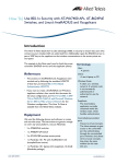
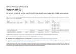
AT-A65 Expansion Module
Installation and Safety Guide
3
V X - X4
0 RE EV
11-0 -00 R
-00-6 611
843 44-000
8
BRO
BCM
AD
C
CO
8823G0829 546 1S
M
A2K
P
82
QM
1A??11
G
2
AT-A65 Expansion Module
AT-A65 Expansion Module Installation and Safety Guide
Document Number 613-001135 Rev A.
Copyright © 2008 Allied Telesis Inc. All rights reserved. No part of this
publication may be reproduced without prior written permission from Allied
Telesis, Inc.
Allied Telesis, Inc. reserves the right to make changes in specifications and other
information contained in this document without prior written notice. The
information provided herein is subject to change without notice. In no event
shall Allied Telesis, Inc. be liable for any incidental, special, indirect, or
consequential damages whatsoever, including but not limited to lost profits,
arising out of or related to this manual or the information contained herein,
even if Allied Telesis has been advised of, known, or should have known, the
possibility of such damages.
All company names, logos, and product designs that are trademarks or
registered trademarks are the property of their respective owners.
613-001135 Rev A
Installation and Safety Guide
3
Package Contents
The following items are included with each AT-A65 expansion module. Contact your
authorised Allied Telesis distributor or reseller if any items are damaged or missing.
■
One AT-A65 expansion module
■
One AT-A65 Expansion Module Installation and Safety Guide
■
One warranty card
Compatible Switches
Caution Attempting to install a module into a switch which is not compatible may
damage the switch and the module. Compatible expansion modules are listed in
your switch’s Hardware Reference. If you are unsure of a module's compatibility,
contact an authorised Allied Telesis distributor or reseller.
The AT-A65 is compatible with the following Allied Telesis switches:
■
AT-8624T/2M
■
AT-8624PoE
To be compatible with the AT-A65, the switch must run software version 2.9.1-17 or
higher of the AlliedWareTM operating system.
Compatible Data Cables and SFPs
The AT-A65 expansion module can act as either a:
■
1000Base-X SFP expansion bay or
■
10/100/1000Base-T copper port with RJ-45 connection
The module can automatically switch between the copper and fiber interface. When
an SFP is installed in the AT-A65, the SFP port is considered the active port and the
copper port becomes disabled. When there is no SFP installed then the copper port
becomes the active port.
SFP expansion bay qualities
The following SFP types are supported:
■
1000Base-SX fiber
■
1000Base-LX fiber
■
1000Base-ZX fiber
10/100/1000Base-T copper and 100Base-FX SFPs are not supported.
613-001135 Rev A
4
AT-A65 Expansion Module
10/100/1000Base-T copper port qualities
The port has the following qualities:
■
10, 100, and 1000Mbps auto-sensing
■
half duplex and full duplex auto-negotiation at 10/100Mbps
■
full duplex auto-negotiation at 1000Mbps
■
auto-MDI / MDI-X
For 10Base-T you can use Category 3 cables or better. For 100/1000Base-T you can
use Category 5 cables or better. The maximum cable length is 100 m (328 ft).
Installing an AT-A65 Expansion Module
You can insert or remove a module while the switch is powered on. The Fault LED
will flash 7 times. You must restart the switch to turn off the flashing LED and make
a module ready for operation.
1. Read the safety information.
For safety information, see the AT-8600 Series Installation and Safety Guide. A copy
of this guide is supplied with each switch, and can also be downloaded from
www.alliedtelesis.com/support/.
2. Gather the tools and equipment you will need.
You will need a screwdriver. You should also have any cables required for
connecting the expansion module to other network devices.
3. Remove the appropriate face-plate or current expansion module on
the switch’s front panel.
Use a screwdriver to loosen the captive screws on the face-plate or expansion
module. When removing an expansion module make sure that when you slide
the module out that it remains aligned with the card guides, as shown in the
figure on the following page.
If no expansion modules are currently installed, then install the AT-A65 into the
switch's left bay. This simplifies VLAN configuration.
If you have removed a face-plate, keep it for future use. If you later remove the
expansion module, replace the face-plate to prevent dust and debris from
entering the switch and to maintain proper airflow.
613-001135 Rev A
Installation and Safety Guide
5
4. Prepare the expansion module.
In an antistatic environment, remove the module from its packing material. Be
sure to observe ESD precautions.
Warning Do not attempt to install an expansion module without observing
correct antistatic procedures. Failure to do so may damage the switch or
expansion module. If you are unsure what the correct procedures are, contact
your authorised Allied Telesis distributor or reseller.
5. Slide the expansion module into place.
Make sure the module is aligned with the card guides on each side of the bay.
Slide the expansion module into the slot until the module face-plate makes
contact with the switch.
card guide
switch_module.eps
6. Secure the expansion module to the switch.
Firmly press the expansion module until its connectors engage the expansion
bay connectors inside the switch. Use a screwdriver to tighten the expansion
module’s screws. Do not over-tighten the screws.
7. Install the SFP if desired
Warning Do not look into the optical ports of SFP cables or transceivers.
Invisible laser radiation may be emitted from disconnected fibres or connectors.
You must insert the SFP transceiver with the release lever hinge at the bottom.
See the following figure as a guide.
To insert an SFP transceiver, slide the transceiver into the SFP socket, and firmly
press it until it engages. To remove an SFP transceiver, first release it by gently
pulling the release lever, then pull it out of the socket. Never force a transceiver
into or out of a socket.
613-001135 Rev A
6
AT-A65 Expansion Module
release lever
hinge
module_sfp.eps
8. Restart the switch.
Until the switch is restarted, the output of the show system and show switch
port commands cannot reflect the newly inserted module or SFP.
When you restart the switch, the Fault LED may flash for approximately 10
seconds as it runs internal tests.
9. Check that the PWR LED on the switch’s front panel lights green.
If the LED fails to light, refer to “Troubleshooting” on page 6.
10. Connect the twisted pair or fiber optic data cable.
If fitted, remove the expansion module’s port dust cover, and connect the data
cable. Make sure the cable connection is secure.
11. Check the expansion module’s LEDs.
Use the table in “AT-A65 Expansion Module LEDs” on page 7 to check the
module’s LEDs. Information on switch system and switch port LEDs can be
found in the Troubleshooting section of the Hardware Reference for your
switch.
Troubleshooting
This section provides information on how to detect and resolve the most common
problems that can cause expansion modules to malfunction. Other sources of
troubleshooting information are:
■
www.alliedtelesis.com.
■
The Software Reference for your switch unit.
Performing the following tasks will eliminate the most common faults:
■
Check that the AT-A65 is correctly installed.
613-001135 Rev A
Installation and Safety Guide
7
■
Make sure the power cord is securely connected to the switch and power
outlet.
■
Check that the power supply voltage to the switch is stable.
■
Check that the correct data cables are being used and that their connections are
secure.
■
Make sure that other network devices are working properly.
■
Use the show install command to check that the latest software version is
loaded. See the AT-8600 Series Software Reference for more information
about obtaining the latest software version.
■
If the switch is malfunctioning, reboot it by pressing the recessed Reset button
or entering the command restart reboot. Alternatively, power OFF and ON
the switch unit by disconnecting and reconnecting the main power supply
(including, if connected, the RPS power).
AT-A65 Expansion Module LEDs
Both the copper and the SFP ports share the same LEDs:
LED
State
Function
10
Green
The port is operating at 10Mbps.
Off
The port is not operating at 10Mbps.
Green
The port is operating at 100Mbps.
Off
The port is not operating at 100Mbps.
Both 10 and 100
Green
The port is operating at 1000Mbps.
FDX
Green
The port is operating in full duplex mode.
Off
The port is operating in half duplex mode.
Flashing green
There is data activity on the port.
Off
There is no data activity on the port.
100
ACT
Environmental Conditions
Operating Temperature
0 to 40º C (32 to 104º F)
Storage Temperature
-25 to 70º C (-13 to 158º F)
Operating Humidity
5% to 90% non-condensing
Storage Humidity
5% to 95% non-condensing
613-001135 Rev A
8
AT-A65 Expansion Module
Regulatory Standards
U.S. Federal Communications Commission
RADIATED ENERGY
Note: This equipment has been tested and found to comply with the limits for a Class A digital device
pursuant to Part 15 of the FCC Rules. These limits are designed to provide reasonable protection
against harmful interference when the equipment is operated in a commercial environment. This
equipment generates, uses, and can radiate radio frequency energy and, if not installed and used in
accordance with this instruction manual, may cause harmful interference to radio communications.
Operation of this equipment in a residential area is likely to cause harmful interference in which case
the user will be required to correct the interference at his own expense.
Canadian Department of Communications
This Class A digital apparatus meets all requirements of the Canadian Interference-Causing
Equipment Regulations.
Cet appareil numérique de la classe A respecte toutes les exigences du Règlement sur le matériel
brouilleur du Canada.
Emissions
EN55022, VCCI, 47 CFR Pt 15 (FCC), AS/NZS CISPR22.
Immunity
EN55024.VCCI
Safety
IEC60590-1, EN60950-1, UL60950-1,
CSA C22.2 No. 60950-1-03, EN60825-1
Where To Find More Information
For further details about your switch, see:
■
The AT-8600 Series Installation and Safety Guide, which provides safety and
statutory information, and outlines the procedure for installing switch units.
■
This AT-8600 Series Switch Hardware Reference.
■
The AT-8600 Series Software Reference, which provides detailed information on
configuring the switch and its software.
For other expansion options for your switch, see:
■
The AT-A45/xx Series, AT-A46, and AT-A47 Expansion Modules Installation Guide,
which outlines the procedure for installing expansion modules, and provides
technical specifications for the modules.
You can download these documents and updates from www.alliedtelesis.com.
You need Adobe® Acrobat® Reader® software to view, search, or print these
documents. You can download it from www.adobe.com.
613-001135 Rev A