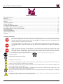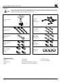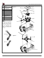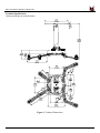
1
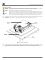
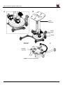
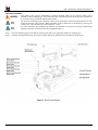
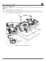
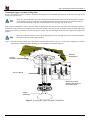
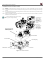
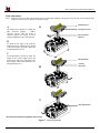
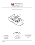
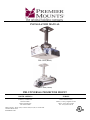
INSTALLATION MANUAL
PBL-UMS (Black)
PBL-UMW (White)
PBL UNIVERSAL PROJECTOR MOUNT
NORTH AMERICA
EUROPE
3130 East Miraloma Avenue
Anaheim, CA 92806 USA
USA and Canada –
Phone: 800-368-9700
Fax: 800-832-4888
Swallow House,
Shilton Industrial Estate,
Shilton, Coventry, England CV79JY
Phone: +44 (0) 2476 614700
Fax: +44 (0) 2476 614710
Other Locations – Phone: (001)-714-632-7100; Fax: (001)-714-632-1044
©Premier Mounts 2010
9530-002-011-09
PBL UNIVERSAL PROJECTOR MOUNT
Table of Contents
Warning Statements .......................................................................................................................................................... - 2 Parts List ........................................................................................................................................................................... - 3 Installation Tools .............................................................................................................................................................. - 3 Features ............................................................................................................................................................................. - 5 Projector Preparation ........................................................................................................................................................ - 6 Bracket Installation ........................................................................................................................................................... - 8 Leveling the Mounting Bracket ........................................................................................................................................ - 9 Securing the Upper Assembly Ceiling Plate ................................................................................................................... - 10 Securing the Projector to the Upper Assembly ............................................................................................................... - 11 Final Adjustments ........................................................................................................................................................... - 12 Plastic Cap Installation ................................................................................................................................................... - 13 Technical Specifications ................................................................................................................................................. - 14 Warranty ......................................................................................................................................................................... - 15 -
Warning Statements
THE CEILING STRUCTURE MUST BE CAPABLE OF SUPPORTING 40 LBS. IF NOT, THE CEILING MUST BE
REINFORCED. PROPER INSTALLATION PROCEDURE BY A QUALIFIED SERVICE TECHNICIAN, AS OUTLINED
IN THE INSTALLATION INSTRUCTIONS, MUST BE ADHERED TO. FAILURE TO DO SO COULD RESULT IN
SERIOUS PERSONAL INJURY, OR EVEN DEATH.
SAFETY MEASURES MUST BE PRACTICED AT ALL TIMES DURING THE INSTALLATION OF THIS PRODUCT.
USE PROPER SAFETY GEAR AND TOOLS FOR THE INSTALLATION PROCEDURE TO PREVENT PERSONAL
INJURY.
PRIOR TO THE INSTALLATION OF THIS PRODUCT, THE INSTALLATION INSTRUCTIONS SHOULD BE READ
AND COMPLETELY UNDERSTOOD. THE INSTALLATION INSTRUCTIONS MUST BE READ TO PREVENT
PERSONAL INJURY AND PROPERTY DAMAGE. KEEP THESE INSTALLATION INSTRUCTIONS IN AN EASILY
ACCESSIBLE LOCATION FOR FUTURE REFERENCE.
Indicates that the power plug is to be disconnected
Contact Premier Mounts with any questions.
from the power outlet.
Safety precautions must be taken at all times.
Warning and Caution statements.
A secure structure must support the weight, or load, of the projector. When mounting to a ceiling that contains wooden studs, dead
center of the wooden stud must be confirmed prior to installation.
Do not install on a structure that is prone to vibration, movement or chance of impact. Failure to do so could result in damage to the
projector and/or damage to the mounting surface.
Do not install near heater, fireplace, direct sunlight, air conditioning or any other source of direct heat energy. Failure to do so may
result in damage to the projector and could increase the risk of fire.
At least two qualified people should perform the installation procedure. Injury and/or damage can result from dropping or mishandling
the projector.
Recommended mounting surfaces: wooden studs and solid-flat concrete. If the mount is to be installed on any surface other than
wooden studs, use suitable hardware (which is commercially available).
Installation Manual
Page 2
PBL UNIVERSAL PROJECTOR MOUNT
Parts List
This mount is shipped with all proper installation hardware and components. Make sure that none of these parts are
missing and/or damaged before beginning installation. If there are parts missing and/or damaged, please stop the
installation and contact Premier Mounts (800) 368-9700.
Upper Assembly®
(Qty 1)
Universal
Mounting
Bracket (Qty 1)
#14 x 2” Wood
Screws (Qty 3)
M2.5 x 10mm
Security head
screws (Qty 4)
M6 x 25 Security
head screw
(Qty 1)
M3 x 12mm
Security head
screws (Qty 4)
M4 x 12 Security
head screws
(Qty 4)
M5 x 12
Security head
screws (Qty 4)
M6 x 12 Security
head screws
(Qty 4)
Plastic barrel
caps (Qty 4)
Installation Tools
Phillips Head Screw Driver
Pencil
Tape Measure
Ladder
Page 3
Portable Drill
1/8” Drill Bit
Stud Finder (Commercially Available)
M5 Security Allen Wrench (Supplied)
Soft Material/ Blanket
Green Level (Supplied)
Installation Manual
PBL UNIVERSAL PROJECTOR MOUNT
A
B
C
D
E
F
G
H
I
J
K
L
M
Single Wooden Stud
Mounts
Solid Structure
Mounting Points
Ceiling Plate
Security Allen Wrench
Extension
Tension Knobs
Safety Knob
Security Screws
Leveling Screws
Universal Mounting
bracket
Leg Assembly
Projector (not included)
Tri-Lock Opening
Option 1
A
B
C
D
E
F
G
H
K
NOTE: The four (two-piece)
leg assemblies can be used as
single leg or any combination
of single and dual legs
together as shown in Options
1 and 2. The number of legs
may vary depending on the
number of mounting points
found on the bottom of the
projector.
I
M
J
L
D
Combination
Leg
M
Option 2
H
Single Leg
J
L
Installation Manual
Page 4
PBL UNIVERSAL PROJECTOR MOUNT
Features
Congratulations on your recent purchase of your PBL Universal Projector Mount. This mounting system is designed for projectors
weighing 40lbs. (18.14 kg) or less. The mount is very easy to install and loaded with additional “no cost” installation features built
into the mount. These features allow you to optimize your projector’s position to the screen for best projector performance and picture
quality.
•
•
•
•
•
•
•
•
•
Page 5
Adjustable-height 9” – 12.5” suspension channel to lower the projectors height (can be removed for low-profile mounting of
only 2.5”)
0°- 45° angled ceiling compensation
Mounts to ceiling or a wall
Tilt / roll up to 20°+
Rotates 360°
Positive locking in any set position
Quick release system for easy projector mounting and removal
Cables can be routed inside the height extension channel
Upper ceiling plate allows for single wood stud mounting and cable insertion through the ceiling plate for clean appearance
Installation Manual
PBL UNIVERSAL PROJECTOR MOUNT
Projector Preparation
Proper installation procedure by qualified personnel as outlined in the installation instructions must be adhered
to. Failure to do so could result in serious personal injury and possible damage to the projector.
THE PROJECTOR IS FRAGILE. HANDLE WITH CARE AT ALL TIMES.
Review the projectors manufacture’s operation manual and refer to the ceiling mounting section of the operator’s
manual. Here you will normally find important reference information regarding installation dimensions such as
(distance from the screen to the lens of the projector, top of the lens placement to the top screen etc. Adherence
to these recommendations during your installation will enhance the quality of your final image on the screen.
Step 1. Carefully invert the projector and place it on a smooth flat surface. Identify the number of mounting points and screw thread
(pitch) size.
Step 2. Most projectors have either three or four mounting points and are M4, M5, or M6 in thread size (Figure 1).
Mounting
Points
Inverted
Projector
Blanket/
Soft Cloth
Flat
Surface
Figure 1. Projector Preparation
Step 3. Separate the upper assembly from the projector mounting bracket by slightly loosening the two tension knurl knobs to create
free play between the bracket tri-lock assembly and the upper section tri-lock assembly points (Figure 2A and 2B).
Step 4. Next loosen the security screw knurl knob far enough to allow the two parts to be rotated 180° apart and separate (Figure
2C).
Installation Manual
Page 6
PBL UNIVERSAL PROJECTOR MOUNT
B
A
Upper
Assembly
Safety
Knob
Tension
Knobs
Rotate 180°
To unlock
C
Tri-Lock
Opening
Figure 2. Mount Preparation
Page 7
Installation Manual
PBL UNIVERSAL PROJECTOR MOUNT
Bracket Installation
Only attach to the projector manufacturer’s specified mounting points on the projector chassis with a
minimum of three mounting legs. Please follow all safety instructions specified by the projector manufacturer
as well as the safety instructions outlined in this manual.
The two-piece mounting legs are designed to allow for the positioning of each leg around projector air vents
located on the base of the projector. Where applicable, each leg mount may be shortened by removing the
locking screw. This will allow for a better bracket fit, overall.
For easier installation, the mounting legs should be first mounted to the projector. Each leg should then be
adjusted so that they can mount to the Universal Mount (Figure 3).
Step 1. Locate the mounting points on the bottom of the projector and use the appropriate number of mounting legs.
Step 2 Select the mounting hardware that the projector requires and loosely install the universal mount on the projector.
Figure 3. Bracket Installation
Installation Manual
Page 8
PBL UNIVERSAL PROJECTOR MOUNT
Leveling the Mounting Bracket
Secure but do not over tighten the mounting hardware. Failure to do so will result in damaging the threads in the
projector.
Step 1. Rotate the leveling barrels to level the mounting bracket.
Step 2. Position the mounting bracket so that it avoids most, if not all, ventilation points (including lamp and filter access doors).
Step 3. When the desired position is achieved, tighten the mounting screws to the projector and then tighten the security hex head leg
screws with the M5 Security Allen Wrench (Figure 4).
M5 Security
Allen Wrench
Level
Inverted
Projector
Leveling
Barrels
DOWN
Adjusting the
Mount.
UP
Figure 4. Leveling the Mounting Bracket
Page - 9 -
Installation Manual
PBL UNIVERSAL PROJECTOR MOUNT
Securing the Upper Assembly Ceiling Plate
Review your projector’s owner’s manual to determine what distance is recommended from the front of the lens to the edge of the
screen for best picture ratio.
However in most home theater and office ceiling mount installations this is not practical as the projector would be
to low within the room. At a minimum you should at least locate the inverted projectors top of the lens point to a
point centered horizontally on the screen and no higher then the top image edge of the screen).
Most projector manufacturers prefer to have the center of the projector lens centered of the top of the screen when the projector is
inverted for ceiling mounting. It is normally better to have the top edge of the lens as close to parallel with the top image edge of the
screen as well. Before you mount your screen and projector, make sure the mounting location will safely support the weight of the
projector.
Make sure to measure from the center of the mounting bracket to the front edge of the lens to determine the proper
placement of the center of the upper assembly.
Step 1. Secure the ceiling assembly into a solid wood ceiling stud with the three (3) #14 x 2” wood screws (supplied) or with other
(commercially available) hardware depending on your installation environment (Figure 5).
Wooden
Ceiling Stud
Ceiling
Structure
#14 x 2” Wood
Secure the ceiling
mount to the center of
the wooden stud.
Upper
Assembly
Figure 5. Securing the Upper Assembly Ceiling Plate
Installation Manual
Page - 10 -
PBL UNIVERSAL PROJECTOR MOUNT
Securing the Projector to the Upper Assembly
Step 1. Make sure the three-knurl knobs are loosened to fully expose to the “tri-lock” mounting plate in the base of the upper
assembly.
Step 2. Carefully lift the projector and insert the mounting bracket mating special tri-lock cutout into the mating portion of the upper
assembly.
Step 3. Once inserted rotate the projector and mounting bracket 180° and secure the rear safety knob first to prevent further rotation
of the bracket in the upper assembly.
Step 4. Tighten the remaining two tension knurl knobs until the mount becomes rigid. The safety knob should line up with the
alignment slot on the mounting bracket.
Follow the numbering sequence prior to securing
the projector to the upper assembly.
The alignment slot
must be in direct
alignment with the
safety knob to lock
the mounting
bracket to the upper
assembly.
1
To secure the
mount, replace the
red safety knurl
knob with one (1)
M6 x 25 security
screw (supplied).
Insert universal bracket
to the tri-lock, then
rotate the projector 180°
2
Tension Knurl
Universal Mount
Tri-Lock Opening
Projector
Alignment Slot
Figure 6. Low Profile Installation
Page - 11 -
Installation Manual
PBL UNIVERSAL PROJECTOR MOUNT
Final Adjustments
Step 1. With the projector secured in the mount and power on and signal supplied to the projector you can now proceed with the final
height, tilt, roll and yaw to optimize the projected image.
Wooden Stud
A
A
The height can be adjusted by rotating the
PBC clockwise (higher) / counterclockwise (lower). Once the height is
achieved, tighten the locking set screw
using the supplied Security Allen Wrench.
Ceiling Structure
Security Allen
Wrench
B
To adjust the tilt angle of the projector,
slightly loosen the side M8 screws and tilt
to the desired angle and firmly tighten the
two M8 adjustment screws.
C
If roll adjustment is needed to square the
images on the screen, slightly loosen the
front and rear M8 screws and adjust to the
desired angle. Then firmly tighten the two
M8 adjustment screws.
Wooden Stud
B
Ceiling
Structure
C
Roll Adjustment
Re-check the hardware for tightness and security.
Figure 7. Final Adjustments
Installation Manual
Page - 12 -
PBL UNIVERSAL PROJECTOR MOUNT
Plastic Cap Installation
Step 1. Once all the final adjustments have been finished install the plastic caps on the leveling barrels (Figure 8).
Figure 8. Plastic Cap Installation
Page - 13 -
Installation Manual
PBL UNIVERSAL PROJECTOR MOUNT
Technical Specifications
All measurements are in inches(mm).
Figure 9. Technical Dimensions
Installation Manual
Page - 14 -
PBL UNIVERSAL PROJECTOR MOUNT
Warranty
PREMIER MOUNTS
LIMITED LIFETIME WARRANTY
What and Who is Covered by this Limited Warranty and for How Long
Premier Mounts warrants this product to be free from defects in material and workmanship for the lifetime of
the original owner of this product. The limited warranty is valid only for the original purchaser of the product.
What Premier Mounts Will Do
At the sole option of Premier Mounts, Premier Mounts will repair or replace any product or product part that is
defective. If Premier Mounts chooses to replace a defective product or part, a replacement product or part will
be shipped to you at no charge, but you must pay any labor costs.
What is Not Covered; Limitations
PR E M I E R M OUNT S DI SC L A I M S A NY L I A B I L I T Y F OR DA M A G E T O M OUNT S, A DA PT E R S,
DI SPL A Y S, PR OJ E C T OR S, OT H E R PR OPE R T Y , OR PE R SO NA L I NJ UR Y R E SUL T I NG , I N
W H OL E OR I N PA R T , F R OM I M PR O PE R I NST A L L A T I ON, M ODI F I C A T I ON, USE OR M I SUSE
OF I T S PR ODUC T S.
PR E M I E R M OUNT S DI SC L A I M S A L L OT H E R W A R R A NT I E S, E X PR E SS OR I M PL I E D,
I NC L UDI NG W A R R A NT I E S OF M E R C H A NT A B I L I T Y A ND F I T NE SS F OR A PA R T I C UL A R
PUR POSE .
PR E M I E R M OUNT S I S NOT R E SPONSI B L E F OR I NC I DE NT A L OR
C ONSE QUE NT I A L DA M A G E S, I NC L UDI NG B UT NOT L I M I T E D T O, I NA B I L I T Y T O USE I T S
PR ODUC T S OR L A B OR C OST S F OR R E M OV I NG A ND R E PL A C I NG DE F E C T I V E PR ODUC T S
OR PA R T S. SOM E ST A T E S DO NOT A L L OW T H E E X C L USI ON OR L I M I T A T I ON OF
I NC I DE NT A L OR C ONSE QUE NT I A L DA M A G E S, SO T H E A B OV E L I M I T A T I ON OR
E X C L USI ON M A Y NOT A PPL Y T O Y OU.
What Customers Must Do for Limited Warranty Service
If you discover a problem that you think may be covered by the warranty you MUST REPORT it in writing to
the address below within thirty (30) days. Proof of purchase (an original sales receipt) from the original
consumer purchaser must accompany all warranty claims. Warranty claims must also include a description of
the problem, the purchaser’s name, address, and telephone number. General inquiries can be addressed to
Premier Mounts Customer Service at 1-800-368-9700. Warranty claims will not be accepted over the phone or
by fax.
Premier Mounts
Attn: Warranty Claim
3130 E. Miraloma Avenue
Anaheim, CA 92806
How State Law Applies
T H I S W A R R A NT Y G I V E S Y OU SPE C I F I C L E G A L R I G H T S, A ND Y OU M A Y A L SO H A V E
OT H E R R I G H T S W H I C H V A R Y F R OM ST A T E T O ST A T E .
Page - 15 -
Installation Manual