1
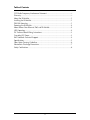
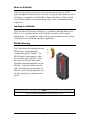
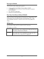
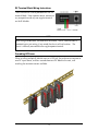
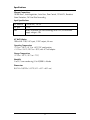
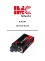
IE-MiniMc
Operation Manual
FCC Radio Frequency Interference Statement
This equipment has been tested and found to comply with the limits for a Class B computing device, pursuant to Part 15 of the FCC Rules.
These limits are designed to provide reasonable protection against harmful interference when the equipment is operated in a commercial
environment. This equipment generates, uses and can radiate radio frequency energy and, if not installed and used in accordance with the
instruction manual, may cause harmful interference to radio communications. Operation of this equipment in a residential area is likely to
cause harmful interference in which the user will be required to correct the interference at his own expense.
Any changes or modifications not expressly approved by the manufacturer could void the user’s authority to operate the equipment.
The use of non-shielded I/O cables may not guarantee compliance with FCC RFI limits. This digital apparatus does not exceed the Class B
limits for radio noise emission from digital apparatus set out in the Radio Interference Regulation of the Canadian Department of
Communications.
Le présent appareil numérique n’émet pas de bruits radioélectriques dépassant les limites applicables aux appareils numériques de classe B
prescrites dans le Règlement sur le brouillage radioélectrique publié par le ministère des Communications du Canada.
Warranty
IMC Networks warrants to the original end-user purchaser that this product, EXCLUSIVE OF SOFTWARE, shall be free
from defects in materials and workmanship under normal and proper use in accordance with IMC Networks' instructions
and directions for a period of six (6) years after the original date of purchase. This warranty is subject to the limitations set
forth below.
At its option, IMC Networks will repair or replace at no charge the product which proves to be defective within such
warranty period. This limited warranty shall not apply if the IMC Networks product has been damaged by unreasonable
use, accident, negligence, service or modification by anyone other than an authorized IMC Networks Service Technician
or by any other causes unrelated to defective materials or workmanship. Any replaced or repaired products or parts carry
a ninety (90) day warranty or the remainder of the initial warranty period, whichever is longer.
To receive in-warranty service, the defective product must be received at IMC Networks no later than the end of the
warranty period. The product must be accompanied by proof of purchase, satisfactory to IMC Networks, denoting
product serial number and purchase date, a written description of the defect and a Return Merchandise Authorization
(RMA) number issued by IMC Networks. No products will be accepted by IMC Networks which do not have an RMA
number. For an RMA number, contact IMC Networks at PHONE: (800) 624-1070 (in the U.S and Canada) or (949) 4653000 or FAX: (949) 465-3020. The end-user shall return the defective product to IMC Networks, freight, customs and
handling charges prepaid. End-user agrees to accept all liability for loss of or damages to the returned product during
shipment. IMC Networks shall repair or replace the returned product, at its option, and return the repaired or new
product to the end-user, freight prepaid, via method to be determined by IMC Networks. IMC Networks shall not be
liable for any costs of procurement of substitute goods, loss of profits, or any incidental, consequential, and/or special
damages of any kind resulting from a breach of any applicable express or implied warranty, breach of any obligation
arising from breach of warranty, or otherwise with respect to the manufacture and sale of any IMC Networks product,
whether or not IMC Networks has been advised of the possibility of such loss or damage.
EXCEPT FOR THE EXPRESS WARRANTY SET FORTH ABOVE, IMC NETWORKS MAKES NO OTHER WARRANTIES,
WHETHER EXPRESS OR IMPLIED, WITH RESPECT TO THIS IMC NETWORKS PRODUCT, INCLUDING WITHOUT
LIMITATION ANY SOFTWARE ASSOCIATED OR INCLUDED. IMC NETWORKS SHALL DISREGARD AND NOT BE
BOUND BY ANY REPRESENTATIONS OR WARRANTIES MADE BY ANY OTHER PERSON, INCLUDING EMPLOYEES,
DISTRIBUTORS, RESELLERS OR DEALERS OF IMC NETWORKS, WHICH ARE
INCONSISTENT WITH THE WARRANTY SET FORTH ABOVE. ALL IMPLIED WARRANTIES INCLUDING THOSE OF
MERCHANTABILITY AND FITNESS FOR A PARTICULAR PURPOSE ARE HEREBY LIMITED TO THE DURATION OF THE
EXPRESS WARRANTY STATED ABOVE.
Every reasonable effort has been made to ensure that IMC Networks product manuals and promotional materials
accurately describe IMC Networks product specifications and capabilities at the time of publication. However, because of
ongoing improvements and updating of IMC Networks products, IMC Networks cannot guarantee the accuracy of printed
materials after the date of publication and disclaims liability for changes, errors or omissions.
i
Table of Contents
FCC Radio Frequency Interference Statement .....................................................i
Warranty.............................................................................................................i
About the IE-MiniMc..........................................................................................1
Installing the IE-MiniMc......................................................................................1
DIN Rail Mounting.............................................................................................1
Powering the IE-MiniMc.....................................................................................2
About Power Over Ethernet (PoE) and IE-MiniMc...............................................2
LED Operation...................................................................................................2
DC Terminal Block Wiring Instructions...............................................................3
Cascading DC Power .........................................................................................3
IMC Networks Technical Support.......................................................................4
Specifications .....................................................................................................5
Fiber Optic Cleaning Guidelines.........................................................................6
Electrostatic Discharge Precautions.....................................................................7
Safety Certifications............................................................................................8
ii
About the IE-MiniMc
The IE-MiniMc Industrial Ethernet miniature media converter features 10/100
switching copper-to-fiber conversion, miniature size, plug-and-play operation, and as
a PD device, is compliant to the IEEE 802.3af Power Over Ethernet (PoE) standard.
The IE-MiniMc supports an extended voltage range as well as extended operating
temperature.
Installing the IE-MiniMc
The IE-MiniMc installs virtually anywhere: as a standalone, table-top device or on a
DIN rail. As a standalone device, install IE-MiniMc in locations with extremely
limited space. Also included, are Velcro strips to attach the device to most surfaces.
A PowerTray/18 is available for high density applications.
DIN Rail Mounting
The IE-MiniMc can be mounted with two
DIN Rail clips, a hardware option
available through IMC Networks. The
DIN Rail clips include screws, to allow
the installation onto a DIN Rail. Install
the screws into DIN Rail clips, which
should be mounted perpendicular to the
DIN Rail. Snap the converter onto the
clips. To remove the converter from the
DIN Rail, use a flat-head screwdriver into
the slot to gently pry the converter from
the rail.
NOTE
The DIN clips are designed for use on a DIN-35 rail.
1
Powering the IE-MiniMc
The IE-MiniMc includes multiple powering options:
•
•
•
•
A country-specific, high-reliability AC power adapter (included)
The IEEE 802.3af Power over Ethernet standard; draws power from power
sourcing equipment
The 4-terminal DC power block
IE-PowerTray/18 for Rack Mounting
About Power Over Ethernet (PoE) and IE-MiniMc
Power Over Ethernet technology allows the IE-MiniMc to be a Powered Device (PD)
and draw power when connected to Power Sourcing Equipment (PSE). Power
Sourcing Equipment distributes an electrical current across existing copper data
cabling.
LED Operation
Each IE-MiniMc includes two LEDs, located on the RJ-45 connector.
LED functions are as follows:
FX LNK/ACT
TX LNK/ACT
Glows green when a link is established on the fiber port; blinks green
when activity is detected on the fiber port.
Glows amber when a link is established on the copper port; blinks
amber when activity is detected on the copper port.
2
DC Terminal Block Wiring Instructions
The IE-MiniMc can also be powered with the DC
terminal block. From a power source, connect to
any one positive and any one negative terminal
on the IE-MiniMc.
+5V DC
NOTE
When using stranded wire, the leads must be tinned. The DC terminal block is
protected against mis-wiring; if mis-wired, the chassis will not function. The
chassis is internally connected to the negative power terminal.
Cascading DC Power
When installing multiple IE-MiniMc units on a DIN rail, the end user can connect to
one DC input source, and then cascade from one DC block to the next, until
reaching the maximum current available.
3
IMC Networks Technical Support
Tel: (949) 465-3000 or (800) 624-1070 (in the U.S. and Canada);
+32-16-550880 (Europe)
Fax: (949) 465-3020
E-Mail: [email protected]
Web: www.imcnetworks.com
4
Specifications
Ethernet Connections
10/100 BaseT, Auto Negotiation, Auto-Cross, Flow Control, 1916 MTU, Broadcast
Storm Protection, Full Line-Rate Forwarding.
Input Specifications
DC terminal
DC jack
PoE
7 to 50 VDC, 1-0.1A
5 VDC
When IE-MiniMc uses PoE technology to be a PD, the maximum
supply voltage is 50V
AC Wall Adapter
100 to 240 ±10% VAC input, 5 VDC output, 2A max.
Operating Temperature
-13°F to +185°F (-25°C to +85°C) DC configuration
+14°F to +122°F (-10°C to +50°C) with AC wall adapter
Storage Temperature
-31°F to +167°F (-35°C to +75°C)
Humidity
5 to 95% (non-condensing); 0 to 10,000 ft. altitude
Dimensions
0.83”H x 1.80”W x 3.35”D (2.11 x 4.57 x 8.51 cm)
5
Fiber Optic Cleaning Guidelines
Fiber Optic transmitters and receivers are extremely susceptible to contamination by
particles of dirt or dust, which can obstruct the optic path and cause performance
degradation. Good system performance requires clean optics and connector ferrules.
1.
Use fiber patch cords (or connectors, if you terminate your own fiber) only from
a reputable supplier; low-quality components can cause many hard-to-diagnose
problems in an installation.
2.
Dust caps are installed at IMC Networks to ensure factory-clean optical devices.
These protective caps should not be removed until the moment of connecting
the fiber cable to the device. Should it be necessary to disconnect the fiber
device, reinstall the protective dust caps.
3.
Store spare caps in a dust-free environment such as a sealed plastic bag or box
so that when reinstalled they do not introduce any contamination to the optics.
4.
If you suspect that the optics have been contaminated, alternate between
blasting with clean, dry, compressed air and flushing with methanol to remove
particles of dirt.
6
Electrostatic Discharge Precautions
Electrostatic discharge (ESD) can cause damage to your add-in modules. Always
observe the following precautions when installing or handling an add-in module or
any board assembly.
1.
Do not remove unit from its protective packaging until you’re ready to install it.
2.
Wear an ESD wrist grounding strap before handling any module or component.
If you do not have a wrist strap, maintain grounded contact with the system unit
throughout any procedure requiring ESD protection.
3.
Hold boards by the edges only; do not touch the electronic components or gold
connectors.
4.
After removal, always place the boards on a grounded, static-free surface, ESD
pad or in a proper ESD bag. Do not slide the board over any surface.
WARNING! Integrated circuits and fiber optic components are
extremely susceptible to electrostatic discharge damage. Do not
handle these components directly unless you are a qualified service
technician and use tools and techniques that conform to accepted
industry practices.
7
Safety Certifications
UL/CUL: Listed to Safety of Information Technology Equipment, including
Electrical Business Equipment.
CE: The products described herein comply with the Council Directive on
Electromagnetic Compatibility (2004/108/EC) and the Council
Directive on Electrical Equipment Designed for use within Certain
Voltage Limits (2006/95/EC). Certified to Safety of Information
Technology Equipment, Including Electrical Business Equipment. For
further details, contact IMC Networks.
Class 1 Laser product, Luokan 1 Laserlaite,
Laser Klasse 1, Appareil A’Laser de Classe 1
European Directive 2002/96/EC (WEEE) requires that any equipment that bears this
symbol on product or packaging must not be disposed of with unsorted municipal
waste. This symbol indicates that the equipment should be disposed of separately
from regular household waste. It is the consumer’s responsibility to dispose of this
and all equipment so marked through designated collection facilities appointed by
government or local authorities. Following these steps through proper disposal and
recycling will help prevent potential negative consequences to the environment and
human health. For more detailed information about proper disposal, please contact
local authorities, waste disposal services, or the point of purchase for this equipment.
8
19772 Pauling • Foothill Ranch, CA 92610-2611 USA
TEL: (949) 465-3000 • FAX: (949) 465-3020
www.imcnetworks.com
© 2010 IMC Networks. All rights reserved.
The information in this document is subject to change without notice. IMC Networks assumes no responsibility for any
errors that may appear in this document. IE-MiniMc is a trademark of IMC Networks. Other brands or product names
may be trademarks and are the property of their respective companies.
Document Number 55-80722-00 A4
November 2010