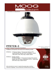
1
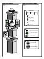
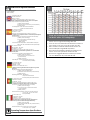
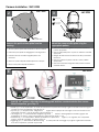
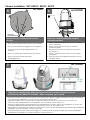
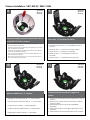
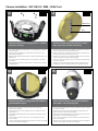
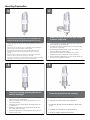
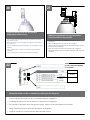
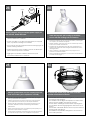
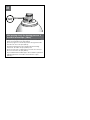
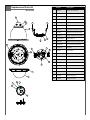
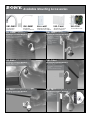
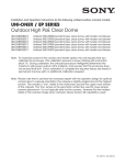
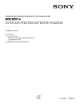
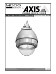
UNI-OPL7 Series
Outdoor Pressurized Dome Housings
Installation and Operation Instructions for the following model:
UNI-OPL7C2
UNI-OPL7T2
Outdoor Pressurized Pendant Housing w/heater & blower, clear lower dome
Outdoor Pressurized Pendant Housing w/heater & blower, tinted lower dome
Note: AC 24V power supply for the camera and the heater/blower is an installer/reseller provided item. Note: Please note that to achieve the increased depth with the aspheric design for optimal camera lens to capsule orientation, the capsule is slightly angled around the highest section. This creates a ”line’, visible to the naked eye, around the upper most section of the capsule. This “line” serves as the geometric center line used to insure proper camera placement. It is not typically seen by the camera. However, Sony RZ series PTZ cameras are able to tilt up above the horizon to 25°, this wide range of tilt motion at a wide angle view may cause this line to be captured in the image.
Mounting instructions for:
SNC-RZ25
SNC-RX530
SNC-RX550
SNC-RX570
SNC-RH124
SNC-RS44
SNC-RS46
Quick Reference: Camera Installation Steps
SNC-RZ25...............................Go to Steps 2-4
SNC-RX Series........................Go to Steps 5-7
SNC-RH/RS.............................Go to Steps 8-15
81-IN6586
10-14-2009
IMPORTANT SAFEGUARDS
1
SAFETY PRECAUTIONS
Read Instructions - All the safety and operating
instructions should be read before the unit is
operated.
2
Retain Instructions - The safety and operating
instructions should be retained for future
reference.
3
Heed Warnings - All warnings on the unit and in
the operating instructions should be adhered to.
4
Follow Instructions - All operating and user
instructions should be followed.
5
Electrical Connections - Only a qualified
electrician should make electrical connections..
6
Attachments - Do not use attachments not
recommended by the product manufacturer as
they may cause hazards.
7
Cable Runs - All cable runs must be within
permissible distance
8
Mounting - This unit must be properly and securely
mounted to a supporting structure capable of
sustaining the weight of the unit.
C AUT ION
RISK OF ELECTRIC SHOCK
DO NOT OPEN
CAUTION: TO REDUCE THE RISK OF ELECTRIC SHOCK,
DO NOT REMOVE COVER (OR BACK).
NO USER SERVICEABLE PARTS INSIDE.
REFER SERVICING TO QUALIFIED SERVICE PERSONNEL
The lightning flash with an arrowhead
symbol, within an equilateral triangle, is
intended to alert the user to the presence
of non-insulated “dangerous voltage”
within the product’s enclosure that may be
of sufficient magnitude to constitute a risk
of electric shock to persons.
The exclamation point within an equilateral
triangle is intended to alert the user to
presence of important operating and
maintenance (servicing) instructions in the
literature accompanying the appliance.
Accordingly:
a. The installation should be made by a qualified installer.
b. The installation should be in compliance with local codes.
c.
Care should be exercised to select suitable hardware to install the unit, taking into account both the composition of the mounting surface and the weight of the unit.
Be sure to periodically examine the unit and the supporting structure to make sure that the integrity
of the installation is intact. Failure to comply with the
foregoing could result in the unit separating from the
support structure and falling, with resultant damages or
injury to anyone or anything struck by the falling unit.
UNPACKING
Unpack carefully. Electronic components can be
damaged if improperly handled or dropped. If an item
appears to have been damaged in shipment, replace
it properly in its carton and notify the shipper.
Be sure to save:
1
The shipping carton and packaging material.
They are the safest material in which to make
future shipments of the equipment.
2
These Installation and Operating Instructions.
SERVICE
If technical support or service is needed, contact Sony
at the following number:
TECHNICAL SUPPORT
8:15AM to 7:30PM (Eastern Time)
1-800-883-6817
If technical support or service is needed, contact
Sony at the following number.
TECHNICAL SUPPORT
8:15 AM to 7:30 PM
(EASTERN TIME)
1-800-883-6817
©2007 Sony Corporation
Contents of Box
Contents of Box Details
A
(1) Spacer Packet
(4) ½”
(8)
25mm
1”
50mm
(4)
2”
200mm
(4) M3 x 6mm Machine Screw
(4) M3 lock washers
(1) 1/4 x 20 Bolt
(1) 1/4 flat washer
B
C
(1) 1/4 lock washer
(3) 8 x 32 x 3/8" bolt
(3) Cable ties
B
(1) 4 Pin Auxiliary Connector
A
(1) 4 Pin Power Connector
(1) RJ45 Coupling
C
(1) Teflon Tape
(1) Pendant Gasket
!
Electrical Specifications
Power 24VAC
Class 2 Only
UNI-OPL7C2
12
1
,5
22
,75
20
1,0
18
1,5
16
2,5
14
4
12
6
10
MM2
AWG
77 Watts at 24 VAC
Heater: 50 Watts
Blower: 1 Watt
Camera: Approximately 25 Watts at 24 VAC*
English
Español
*Refer to applicable camera specs for precise consumption.
Input Connectors (Outdoor Units):
(1) BNC (Analog Video)
(2) Screw-Down Connectors (Power/Alarms)
(1) RJ45 (Data)
Tools Required: .100” Flat Head Screwdriver
Phillips Head Screwdriver
77 vatios en 24 VAC
Calentador: 50 vatios
Soplador: 1 vatio
Cámara: Aproximadamente 25 Watts a 24 VAC *
* Consulte con las especificaciones de la cámara aplicable para el
consumo exacto.
Conectadores De la Entrada (Unidades Al aire libre):
(1) BNC (Vídeo Análogo)
(2) Conectadores Del Tornillo-Abajo
(Power/Alarms)
(1) RJ45 (datos)
Las Herramientas Requirieron: Destornillador Principal
Plano Del 100" Destornillador Principal Phillips
77 watts à 24 VCA
Réchauffeur : 50 watts
Ventilateur : 1 watt
Appareil photo: Environ 25 Watts à 24 VAC *
Français
Deutsch
* Se reporter aux spécifications applicables à la consommation
caméra précis.
Connecteurs D'Entrée (Unités Extérieures) :
(1) BNC (Vidéo Analogue)
(2) Connecteurs De Vis-Vers le bas
(Power/Alarms)
(1) RJ45 (données)
Outils Requis : Tournevis Principal Plat De 100"
Tournevis Principal Phillips
77 Watt bei 24 VAC
Heizung: 50 Watt
Gebläse: 1 Watt
Kamera: ca. 25 W bei 24 VAC *
* Wenden Sie sich an geltenden Kamera Angaben zur genauen
Verbrauch.
Eingang Stecker (Im Freienmaßeinheiten):
(1) BNC (Analoger Bildschirm)
(2) Schraube-Unten Stecker (Power/Alarms)
(1) RJ45 (Daten)
Werkzeuge Erfordert: 100"Flacher
Hauptschraubenzieher
Kreuzkopfhauptschraubenzieher
77 watts em 24 VAC
Calefator: 50 watts
Ventilador: 1 watt
Camera: Aproximadamente 25 Watts a 24 VCA *
Portuguese * Consulte a Ficha câmera aplicável ao consumo precisa.
Italiano
Conectores Da Entrada (Unidades Ao ar livre):
(1) BNC (Vídeo Análogo)
(2) Conectores Do Parafuso-Para baixo
(Power/Alarms)
(1) RJ45 (dados)
Ferramentas Requeridas: Chave de fenda Principal
Lisa Do 100". Chave de fenda
Principal Phillips
77 watt a 24 VCA
Riscaldatore: 50 watt
Ventilatore: 1 watt
Fotocamera: Circa 25 Watt a 24 VAC *
* Fare riferimento a specifiche fotocamera applicabili per il
consumo precise.Connettori Dell'Input (Unità Esterne):
(1) BNC (Video Analog)
(2) Connettori Della Vite-Giù (Power/Alarms)
(1) RJ45 (dati)
Attrezzi Richiesti: Cacciavite Capo Piano Del 100"
Cacciavite Capo "phillips"
Operating Temperature Specifications
-40°C to + 50°C (-40°F to +122°F)
These
are recommended
distances
The
beam
angle may bemaximum
adjusted on
the
for
24VAC
with
a
10%
voltage
drop.
bottom of the unit.
• Éstos se recomiendan las distancias máximas para
24VAC con una gota del voltage del 10%.
• Ceux-ci sont recommandés des distances maximum
pour 24VAC avec une chute de tension de 10%.
• Diese werden maximale Abstände für 24VAC mit
einem 10% Spannungsabfall empfohlen.
• Estes são recomendados distâncias máximas para
24VAC com uma queda de tensão de 10%.
• Questi sono suggeriti distanze massime per 24VAC
con una differenza de potenziale di 10%.
Camera Installation: SNC-RZ25
SNC-RZ25
2
3
SNC-RZ25
SNCRZ25
(2) 3mm screws
(1) ¼”x 20 bolt
lock washer
SNCRZ25
MOUNTING HOLES
Remove the quick release plate from the
housing.
Mount the camera to the plate using the
appropriate pattern.
• Quite la placa rápida del lanzamiento de la cubierta.
• Monte la cámara fotográfica a la placa usando el
patrón apropiado.
• Montez l'appareil-photo au plat en utilisant le modèle
approprié.
• Bringen Sie die Kamera zur Platte mit dem passenden
Muster an.
• Monte a câmera à placa usando o teste padrão
apropriado.
• Monti la macchina fotografica alla piastra usando il
modello adatto.
• Enlevez le plat rapide de dégagement du logement.
• Entfernen Sie die schnelle Freigabeplatte vom
Gehäuse.
• Remova a placa rápida da liberação da carcaça.
• Rimuova la piastra rapida del rilascio
4
SNC-RZ25
1/2” Spacers
or standoffs
Add (4) 1/2” spacers, align tabs in mounting plate and turn counterclockwise then secure.
16.
When completed, go to step 12.
• Añadir (4) 1 / 2 "de separación, se suman las pestañas en la placa de montaje y gire en sentido entonces seguro.
16.
Cuando se haya completado, vaya al paso 12.
• Ajouter (4) 1 / 2 "d'espacement, l'alignement des onglets dans la plaque de montage et de tourner dans le sens
16.
antihoraire sécurisée. Une fois terminé, passez à l'étape 12.
• "Hinzufügen" (4) 1 / 2 "Abstandhalter, Angleichung der Registerkarten in Montageplatte und dann gegen den
16 fort.
Uhrzeigersinn zu sichern. Wenn abgeschlossen, fahren Sie mit Schritt 12
• Adicionar (4) 1 / 2 "espaçadores, alinhar separadores na placa de montagem e, em seguida, vire à esquerda
segura. Quando concluído, vá para a etapa 16.
12.
• Aggiungi (4) 1 / 2 "Distanziatori, allineare le linguette nella piastra di montaggio e poi girate a garantire antiorario.
Una volta completato, passare al punto 12.
16.
Camera Installation: SNC-RX530 / RX550 / RX570
5
SNC-RXSERIES
SNCRX550
6
SNC-RXSERIES
SNCRX550
(4) 3mm screws
SNC RX550
MOUNTING HOLES
Remove the quick release plate from the
housing.
Mount the camera to the plate using the
appropriate pattern.
• Quite la placa rápida del lanzamiento de la cubierta.
• Monte la cámara fotográfica a la placa usando el
patrón apropiado.
• Montez l'appareil-photo au plat en utilisant le
modèle approprié.
• Bringen Sie die Kamera zur Platte mit dem passenden Muster an.
• Monte a câmera à placa usando o teste padrão
apropriado.
• Monti la macchina fotografica alla piastra usando
il modello adatto.
• Enlevez le plat rapide de dégagement du logement.
• Entfernen Sie die schnelle Freigabeplatte vom
Gehäuse.
• Remova a placa rápida da liberação da carcaça.
• Rimuova la piastra rapida del rilascio
dall'alloggiamento.
7
SNC-RXSERIES
Align tabs in mounting plate with the base plate and turn counterclockwise to secure.
NO SPACERS OR STANDOFFS REQUIRED. When completed, go to step 12.
16.
• Alinee las pestañas en la placa de montaje con la placa base y girar en sentido antihorario para seguro. SPACERS O
16.
NO OBLIGATORIO STANDOFFS. Cuando se haya completado, vaya al paso 12.
• Alignez les onglets dans une plaque de montage avec la plaque de base et à assurer son tour dans le sens
16.
antihoraire. SPACERS STANDOFFS OU NON REQUIS. Une fois terminé, passez à l'étape 12.
• Richten Sie Registerkarten in Montageplatte mit der Bodenplatte und dann gegen den Uhrzeigersinn zu sichern. NO
SPACERS ODER Standoffs REQUIRED. Wenn abgeschlossen, fahren Sie mit Schritt 16
12 fort.
• Alinhar guias na montagem da chapa com base prato e vire à esquerda para garantir. SPACERS OU NÃO STANDOFFS
16.
REQUIRED. Quando concluído, vá para a etapa 12.
• Allineare le linguette nella piastra di montaggio con la piastra di base e girare antiorario per sicurezza. DISTANZIALI
STANDOFFS N O RICHIESTE. Una volta completato, passare al punto 16.
12.
Camera Installation: SNC-RH124 / RS44 / RS46
8
SNC-RH124
SNC-RS44
SNC-RS46
Remove existing bracket to mount SNC-RH124
or the SNC-RS series cameras.
• Retire el soporte existentes para organizar SNC-RH124 o la
SNC-cámaras de la serie RS.
• Retirez le support afin de faire face SNC-RH124 ou le Groupe
SNC-caméras de la série RS.
• Entfernen Sie vorhandene Halterung an SNC-mount-RH124
oder die SNC-RS-Serie Kameras.
• Remover suporte existente para montar SNC-RH124 ou do
SNC câmeras da série RS.
• Rimuovere supporto esistente per montare SNC-RH124 o la
SNC-telecamere della serie RS.
10
SNC-RH124
SNC-RS44
SNC-RS46
Add four additional 1/2” spacers.
• Agregue cuatro adicional de 1 / 2 "espaciadores.
• Ajoutez quatre supplémentaire de 1 / 2 "entretoises.
• Fügen Sie vier weitere 1 / 2 "Abstandshalter.
• Adicionar quatro adicional de 1 / 2 "espaçadores.
• Aggiungere quattro ulteriori 1 / 2 "distanziali.
9
SNC-RH124
SNC-RS44
SNC-RS46
Leave four 1/2” spacers as shown.
• Vacaciones de cuatro 1 / 2 "separadores como se
muestra.
• Laissez quatre 1 / 2 "espaceurs comme indiqué.
• Lassen Sie vier 1 / 2 "Spacer, wie gezeigt.
• Deixar quatro 1 / 2 "espaçadores, conforme
mostrado.
• Lascia quattro 1 / 2 "distanziali come mostrato.
11
SNC-RH124
SNC-RS44
SNC-RS46
Camera bracket should now appear as
shown.
• Soporte de cámara Shaud ahora aparecen como se
muestra.
• Support pour caméra devrait maintenant s'afficher
comme indiqué.
• Kamerahalterung shoud jetzt wie abgebildet
angezeigt.
• Suporte de câmera shoud agora aparecerá como
mostrado.
• Staffa Camera shoud ora appaiono come mostrato.
Camera Installation: SNC-RH124 / RS44 / RS46 Cont.
12
SNC-RH124
SNC-RS44
SNC-RS46
13
SNC-RH124
SNC-RS44
SNC-RS46
24VAC Power
RJ45
Attach the SNC RH124 ceiling plate to 1” (25mm)
spacers in housing
Connect control and power wires to camera
base, (see Sony camera instructions)
• Ate la placa del techo de SNC RH124” a los espaciadores 1 (de 25m
m) en la cubierta
• Conecte el control y accione los alambres a la base de la cámara,
(véase las instrucciones de la cámara de Sony)
• Attachez le plat de plafond de SNC RH124 » aux entretoises 1 (de
25mm) dans le logement
• Reliez la commande et actionnez les fils à la base d'appareil-photo,
(voir les instructions d'appareil-photo de Sony)
• Bringen Sie SNC RH124 Deckenplatte zu“ (25mm) Distanzscheiben 1 im
Gehäuse an
• Schließen Sie Steuerung an und treiben Sie Drähte zur Kameraunterseite an, (sehen Sie Sony-Kameraanweisungen)
• Una a placa do teto de SNC RH124” aos espaçadores 1 (de 25mm)
na carcaça
• Conecte o controle e pnha fios à base da câmera, (veja instruções
da câmera de Sony)
• Attacchi il piatto del soffitto di SNC RH124„ ai distanziatori 1 (di 25mm)
in alloggiamento
• Colleghi il controllo ed alimenti i legare alla base della macchina
fotografica, (vedi le istruzioni della macchina fotografica di Sony)
14
SNC-RH124
SNC-RS44
SNC-RS46
Attach base plate to ceiling plate with hardware
provided with camera
15
SNC-RH124
SNC-RS44
SNC-RS46
Attach main connector and install camera to
base plate. Secure locking pins
• El embase de la fijación a la placa del techo con hardware
proporcionó la cámara
• Ate el conectador principal e instale la cámara al embase. Asegure
las clavijas de cierre
• L'embase d'attache au plat de plafond avec le matériel a fourni en
appareil-photo
• Attachez le connecteur principal et installez l'appareil-photo sur
l'embase. Fixez les chevilles de verrouillage
• Grundplatte der Befestigungs zur Deckenplatte mit Hardware versah
mit Kamera
• Bringen Sie Hauptverbindungsstück an und bringen Sie Kamera zur
Grundplatte an. Sichern Sie Sicherungsstifte
• A placa baixa do anexo à placa do teto com ferragem forneceu
com a câmera
• Una o conector principal e instale a câmera à placa baixa. Fixe os
pinos de travamento
• La base di appoggio dell'attaccatura al piatto del soffitto con fissaggi
ha fornito la macchina fotografica
• Attacchi il connettore principale ed installi la macchina fotografica
alla base di appoggio. Fissi i perni di bloccaggio
Mounting Preparation
16
17
Wrap Teflon tape around the pipe threads
to ensure a tight seal.
TM
Securely attach pendant pipe or the UNI-WMB1. Pull
wiring through pipe and position grommet as shown.
• Segura adjuntar colgante o de la tubería de UNI-WMB1. Tire de la
tubería y el cableado a través de un drenaje timpánico posición como
se muestra.
• Securely joindre pendant la pipe ou le UNI-WMB1. Pull de câblage à
travers la pipe et la position œillet comme indiqué.
• Sicher befestigen Anhänger Rohr oder die UNI-WMB1. Ziehen Sie
Verkabelung durch Rohr-und Kabeldurchführungen Position wie
gezeigt.
• Securely anexar pingente cachimbo ou o UNI-WMB1. Puxar fiação
através do tubo e posição grommet como mostrado.
• Sospensione fissa tubo o la norma UNI-WMB1. Estrarre il tubo attraverso il
cablaggio e la posizione grommet come mostrato in figura.
18
Screw the coupling onto the pipe threads
until it is hand tight.
• Atornille el acoplador sobre los hilos de rosca de la pipa
hasta que es mano firmemente.
• Vissez le couplage sur les fils de pipe jusqu'à ce que ce
soit main fortement.
• Schrauben Sie die Koppelung auf die Rohrgewinde, bis
es Hand fest ist.
• Parafuse o acoplamento nas linhas da tubulação até
que esteja mão firmemente.
• Avviti l'accoppiamento sui filetti del tubo fino a che non
sia fortemente mano.
• La cinta del Teflon del abrigo alrededor de la pipa rosca
para asegurar un sello apretado.
• La bande de teflon d'enveloppe autour de la pipe filète
pour assurer un joint serré.
• Verpackung Teflonklebeband um das Rohr verlegt, um
eine feste Dichtung sicherzustellen.
• A fita adesiva do Teflon do envoltório em torno da
tubulação enfía para assegurar um selo apertado.
• Il nastro del Teflon dell'involucro intorno al tubo filetta per
accertare una guarnizione stretta.
19
Screw the (2) bolts into the coupling.
• Atornille (2) los pernos en el acoplador.
• Vissez (2) les boulons dans l'accouplement.
• Schrauben Sie die (2) Schraubbolzen in die Koppelung.
• Parafuse (2) os parafusos no acoplamento.
• Avviti (2) i bulloni nell'accoppiamento.
21
6
20
Loop the lanyard over the set screw to
temporarily hold housing.
Make the appropriate wiring connections
from the dome to the pendant.
• Loop el cordón sobre el tornillo de fijación para mantener temporalmente de la vivienda.
• Boucle de la longe sur la vis de réglage pour détenir temporairement
des logements.
• Loop das Trageband über die Stellschraube, um vorübergehend halten
Gehäuse.
• Loop o colhedor sobre o parafuso para prender temporariamente
habitação.
• Loop il cordino sulla vite di tenere temporaneamente alloggi.
• Hacer las conexiones de cableado de la cúpula de la
pendiente.
• Faites le câblage de la coupole de la suspension.
• Nehmen Sie die entsprechenden Kabel-Verbindungen von der
Kuppel auf den Anhänger.
• Faça as conexões de cabos da cúpula para o pingente.
• Apportare le opportune connessioni cablaggio dalla cupola a
ciondolo.
22
Please refer to camera
product manuals regarding
consumption
Four Position Connector
Power
77 Watts
Wiring the dome can be completed by referring to the diagram.
• Atar con alambre la bóveda puede ser terminada refiriendo al diagrama.
• Le câblage du dôme peut être accompli en se rapportant au diagramme.
• Das Verdrahten der Haube kann durchgeführt werden, indem man auf das Diagramm sich bezieht.
• Wiring a abóbada pode ser terminado consultando ao diagrama.
• Legare la cupola può essere completato riferendosi allo schema.
23
Green
Jumpers
Wires from
Dome
Yellow
24
Orange
Red
Input
-
+
Add 2 jumpers if using a common power supply for
the camera, heater & blower.
• Añadir 2 jumpers si utiliza una fuente de alimentación para la
cámara, calefacción y ventilador.
• Ajoutez 2 cavaliers si vous utilisez une alimentation pour l'appareil
photo, appareil de chauffage et de soufflerie.
• Add 2 Jumper, wenn Sie eine gemeinsame Stromversorgung für die
Kamera, Heizung & Gebläse.
• Adicionar 2 jumpers comum se utilizar uma fonte de alimentação
para a câmara, aquecedor e ventilador.
• Aggiungere 2 ponticelli se si utilizza un alimentatore per la
fotocamera, riscaldamento e ventilatore.
25
Slide the grommet down over the coupling to prevent
water from entering and complete the assembly.
• Resbale el ojal abajo sobre el acoplador para evitar que el agua
entre y para terminar a la asamblea.
• Glissez le canon isolant vers le bas au-dessus de l'accouplement
pour empêcher l'eau d'entrer et pour accomplir l'assemblée.
• Schieben Sie die Gummimuffe unten über der Koppelung, um zu
verhindern, daß Wasser und die Versammlung durchzuführen
hereinkommt.
• Deslize o ilhó para baixo sobre o acoplamento para impedir que a
água entre e para terminar o conjunto.
• Faccia scorrere il gommino di protezione giù sopra l'accoppiamento
per impedire l'acqua entrare e per completare il complessivo.
Undo the lanyard, pull housing up and twist
secure with the locking bolt and washers.
• Deshaga el acollador, tire de contener para arriba y tuerza seguro
con el perno y las arandelas de fijación.
• Défaites la lanière, tirez loger vers le haut et tordez bloqué avec le
boulon et les rondelles de fermeture.
• Annulieren Sie die Abzuglinie, ziehen Sie oben unterbringen und
verdrehen Sie sicheres mit dem verriegelnschraubbolzen und den
Unterlegscheiben.
• Undo o colhedor, puxe abrigar acima e torça seguro com o
parafuso e as arruelas travando.
• Undo la cordicella, tiri l'alloggio in su e torca sicuro con il bullone e
le rondelle di bloccaggio.
26
To install the dome align the tabs and twist
counter clockwise to secure.
• Para instalar la bóveda alinee las lengüetas y tuerza al revés
a la derecha para asegurar.
• Pour installer le dôme alignez les étiquettes et tordez contre
dans le sens des aiguilles d'une montre pour fixer.
• Um die Haube anzubringen richten Sie die Vorsprünge aus
und verdrehen Sie sich entgegengesetzt nach rechts um zu
sichern.
• Para instalar a abóbada alinhe as abas e torça-as contra no
sentido horário para fixar-se.
• Per installare la cupola allinei le linguette e torca contro in
senso orario per fissare.
Pressurizing Instructions
27
28
100
580
Fitting
50
0
150
Air Chuck
200
250
PSI 300
Hose
Regulator
Nitrogen
Tank
Hand tighten the screws on the dome.
Recommended torque 12 inches/lb (1.35Nm).
When pressurizing unit be sure to set the
guage or regulator from 10-20psi (.7-1.4bar).
• La mano aprieta los tornillos en la bóveda. Esfuerzo de
torsión recomendado 12 inches/lb (el 1.35Nm).
• La main serrent les vis sur le dôme. Couple recommandé 12 inches/lb (1.35Nm).
• Hand ziehen die Schrauben an der Haube fest.
Empfohlene Drehkraft 12 inches/lb (1.35Nm).
• A mão aperta os parafusos na abóbada. Torque
recomendado 12 inches/lb (1.35Nm).
• La mano stringe le viti sulla cupola. Coppia di torsione
suggerita 12 inches/lb (1.35Nm).
• Al presurizar la unidad sea seguro fijar la medida o el
regulador de 10-20psi (7-1.4bar).
• En pressurisant l'unité soyez sûr de placer la jauge ou le
régulateur de 10-20psi (7-1.4bar).
• Wenn Sie Maßeinheit unter Druck setzen, seien Sie sicher,
das Eichmaß oder den Regler von 10-20psi (7-1.4bar)
einzustellen.
• Ao pressurizar a unidade seja certo ajustar o guage ou o
regulador de 10-20psi (7-1.4bar).
• Nel pressurizzare l'unità sia sicuro regolare il misuratore o
il regolatore da 10-20psi (7-1.4bar).
29
30
Air Chuck
Tank
Valve
Place the air chuck on the tank valve and
begin filling until pressure relief valve opens.
Open the relief valve. Drain all air from the housing and
repeat twice to remove all moisture.
• Coloque la tirada del aire en la válvula del tanque y comience
• Abra la válvula de descarga. Drene todo el aire de la cubierta y
de la repetición dos veces para quitar toda la humedad.
• Ouvrez la soupape de sécurité. Évacuez tout l'air le logement et la
répétition deux fois pour enlever toute l'humidité.
• Öffnen Sie das Sicherheitsventil. Lassen Sie alle Luft aus dem
Gehäuse und der Wiederholung zweimal ab, um alle Feuchtigkeit
zu entfernen.
• Abra a válvula de escape. Drene todo o ar da carcaça e do
repeat duas vezes para remover toda a umidade.
• Apra la valvola di sfiato. Vuoti due volte tutta l'aria
dall'alloggiamento e dalla ripetizione per rimuovere tutta l'umidità.
•
•
•
•
a llenar hasta que la válvula de descarga de presión se abre.
Placez le mandrin d'air sur la valve de réservoir et commencez
à remplir jusqu'à ce que la valve de décompression s'ouvre.
Setzen Sie die Luftklemme auf das Behälterventil und fangen Sie
an zu füllen, bis Druckablaßventil sich öffnet.
Coloque o mandril do ar na válvula do tanque e comece a
encher-se até que a válvula de escape de pressão abra.
Disponga il mandrino dell'aria sulla valvola del carro armato e
cominci a riempirsi fino a che la valvola limitatrice della
pressione non si apra.
31
10
5
0
15
20
25
PSI 30
After purging check the housing pressure. It
should be around 5psi (.34bar).
• Después de purgar el cheque la presión de la cubierta.
Debe estar alrededor de 5psi (34bar).
• Après la purge du contrôle la pression de logement. Elle
devrait être autour de 5psi (34bar).
• Nachdem Überprüfung der Gehäusedruck bereinigt
worden ist. Sie sollte um 5psi (34bar) sein.
• Após ter removido a verificação a pressão da carcaça.
Deve ser em torno de 5psi (34bar).
• Dopo l'eliminazione dell'inceppo del controllo la pressione
dell'alloggiamento. Dovrebbe essere intorno a 5psi
(34bar).
32
How - to Clean a Dome Bubble
To effectively clean your video surveillance dome bubble (acrylic or
polycarbonate) from debris, follow these simple step-by-step instructions.
Materials Needed
•
•
•
•
•
Clean, dry, pressurized air
Water
High quality soft paper towel
Isopropyl alcohol (rubbing alcohol)
Scratch-resistant cloth
Cleaning Dome Exterior
1. When cleaning exterior of dome, make sure bubble is connected
securely to the camera housing.
2. While utilizing a nonabrasive cloth and cleaning agent, safe for use
on acrylic or polycarbonate plastic, in a spiral motion, gently clean
exterior of bubble.
3. Dry immediately with dry, pressurized air to prevent water spots.
Cleaning Dome Interior
1. Safely remove the dome bubble from the camera housing. To
prevent scratches or additional imperfections, utilize a scratchresistant cloth when handling the bubble.
2. Once removed, carefully place the bubble on a clean surface, safe
from dust and any other foreign debris. Do not place the bubble
face down on its curved surface.
3. While holding onto the bubble, use clean, dry, pressurized air to
gently blow off all loose particles. For more thorough cleaning, try
one of the following:
i. Rinse bubble with water and immediately dry with
pressurized air to prevent water spots
ii. Roll a section of high-quality paper towel into a tube,
and tear tube in half. Wet torn edge with rubbing
alcohol solution (75% alcohol & 25% water). While
holding the bubble facing downward, wipe the interior
with the paper towel tube in a circular motion from the
outside – in. Use spiraling motions when cleaning.
Repeat above steps to clean entire bubble.
Replacement Parts List
UNI-OPL7C2
2
4
3
16
17
1
15
14
13
1
15
17
13
5
14
Part No.
Description
1
RPPFDT02
Housing Top (Extended)
2
RPVL1938
Removable Pendent Coupling
3
RPVL1802
Plastic Rain Shroud
4
RPVL1795
Tank Valve Gasket
5
RP96RSORG11
Main O-Ring 9.25"
6
RPPFDTR01
Trim Ring w/o Dome
7
RCPFD7
Clear Dome with sealing O-Ring
7b
RCTPFD7
Tinted Dome with sealing O-Ring
8
RPPFDT03
Internal Sealing Bracket Assembly
9
RP96RSORG10
Small O-Ring 4.5"
10
RP70PT07a
Hermetic Connector, Gasket, Cable
11
RP95VALV08
5 to 7 psi Pressure Relief Valve
12
RP95VALV07
Tank Valve
13
RPFD072
24VAC Heater
14
RPVL1798a
½" Spacers (Set of 4)
15
RP40PCPPFD8
Connection PCB Assembly
16
RPFD060
Main Bracket Assembly
17
RPFD080
Blower
N/S
RP40CAPPFD811
External Input Video/Power Cables
N/S
RP46PKH2220
Packet Assembly-Hardware
N/S
RP46PKH1120
Packet Assembly-Electrical
N/S
RPVL2636
Adaptor Ring (Sony)
N/S
RPVL2825
Mount Plate (Sony)
16
7
6
8
10
11
9
12
Available Mounting Accessories
UNI-WMB1
UNI-RMB1
Aluminum
Parapet Mount
Gooseneck
Wall Mount
UNI-WMB1
Wall Mount
Mounting Accessories Needed:
UNI-PMA1
Aluminum Existing
Pole Mount Adaptor
UNI-CMA1
Aluminum Corner
Mount Adaptor
UNI-PBU1
Power Block Unit
UNI-PMA1 Pole Mount
Mounting Accessories Needed:
UNI-WMB1 - Gooseneck Wall Mount
Outdoor Pendant Housing
• UNI-WMB1 - Gooseneck
Wall Mount
• UNI-PMA1 - Aluminum
Exising Pole Mount
Adaptor
• Outdoor Pendant
Housing
UNI-RMB1 RoofMount (Parapet)
Mounting Accessories Needed:
UNI-CMA1 Corner Mount
Mounting Accessories Needed:
UNI-RMB1 - Aluminum Parapet Mount
Outdoor Pendant Housing
• UNI-CMA1 - Aluminum Corner
Mount Adaptor
• UNI-WMB1 - Gooseneck Wall
Mount
• Outdoor Pendant Housing
UNI-PBU1 Power Block Unit (Wall Mount)
Mounting Accessories Needed:
UNI-PBU1 Power Block Unit (Pole Mount)
Mounting Accessories Needed:
UNI-WMBI - Gooseneck Wall Mount
• UNI-WMB1 Gooseneck Wall
Mount
Warranty
For warranty information on this and other Sony Security Systems Products, please visit:
http://pro.sony.com/bbsccms/services/files/servicesprograms/SecurityWarranty.pdf