1
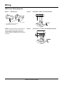
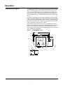
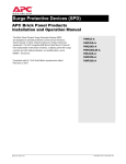
Installation and
Operation Manual
APC 2X Series
Hardwire Products
PMP2X-A
PMF2X-A
PMG2X-A
PMH2X-A
APC hardwired products are designed to provide specification-grade performance at the service entrance, branch panels, or
other critical locations for today’s electrical distribution systems. APC Hardwire Panel Mount Products package multi-phase surge
suppression and noise suppression into a compact, economical NEMA 4x enclosure. The units come standard with an audible
alarm, dry contacts, and status indicator LEDs.
Compliant with UL1449 3rd Edition requirements dated September 29, 2009.
Table of Contents
Precautions ............................................................................................... 4
Introduction ............................................................................................... 6
Unpacking and Preliminary Inspection ................................................... 7
Storage ....................................................................................................... 7
Identification Nameplate .......................................................................... 7
SPD Location Considerations ................................................................. 7
Environment ................................................................................................ 7
Audible Noise .............................................................................................. 7
Mounting ..................................................................................................... 7
Service Clearance ....................................................................................... 7
Equipment Performance ............................................................................. 7
Electrical .................................................................................................... 8
Voltage Rating ............................................................................................ 8
Wire Leads .................................................................................................. 9
Branch Circuit Overcurrent Protection and Disconnect Means ................... 9
Location of Surge Protective Device (SPD) .............................................. 10
System Grounding .................................................................................. 11
Installation ............................................................................................... 12
Mounting Recommendations .................................................................... 12
Wiring ....................................................................................................... 13
PM2X Series Wiring Diagrams ................................................................. 14
Operation ................................................................................................. 15
LED Status Indicators ............................................................................... 15
Audible Alarm ............................................................................................ 15
Dry Contacts ............................................................................................. 16
Remote Monitor Option ............................................................................. 17
Preventive Maintenance ......................................................................... 18
Customer Support ................................................................................... 20
Installation and Operation Manual
3
Precautions
Precautions
DANGER
HAZARD OF ELECTRIC SHOCK, EXPLOSION, OR ARC FLASH
• Apply appropriate personal protective equipment (PPE) and follow safe
electrical work practices. See NFPA 70E.
• This equipment must only be installed and serviced by qualified electrical personnel.
• Turn off all power supplying this equipment before working on or inside
equipment.
• Always use a properly rated voltage sensing device to confirm power is off.
• Replace all devices, doors and covers before turning on power to this
equipment.
• This equipment must be effectively grounded per all applicable codes.
Use an equipment-grounding conductor to connect this equipment to
the power system ground.
Failure to follow these instructions will result in death or serious injury.
CAUTION
LOSS OF BRANCH CIRCUIT POWER / LOSS OF SURGE
SUPPRESSION
• Ensure that the branch circuit breaker or fuse trip characteristic has
been coordinated with the overcurrent protection inside the SPD
(See Table 1).
• Perform periodic inspection of the SPD status indicator lights as part of
the preventative maintenance schedule.
• Promptly service the SPD when an alarm state exists.
• Use dry contacts to signal an alarm state to the central supervisory system for unmanned, inaccessible, or critical installations.
• Use multiple SPDs to achieve redundancy for critical applications.
Failure to follow these instructions can result in injury or
equipment damage.
At end-of-life conditions, Surge Protective Devices (SPDs) can lose their
ability to suppress power system voltage and attempt to draw excessive
current from the line. This SPD is equipped with overcurrent and
overtemperature components that will automatically disconnect the surge
suppression elements from the mains should the surge suppression
elements reach end of life. Tripping of the branch circuit breaker or fuse
feeding the SPD can occur. Mitigate the tripping of the branch circuit
breaker or fuse feeding the SPD by coordinating the surge suppression
elements with the branch circuits.
For the purposes of coordination, the SPD is equipped with overcurrent
components that will limit the per phase I2t, Iapparent, Ip, and Ith values to
those listed in Table 1 when connected to a power system with a shortcircuit current rating not exceeding 200,000 A.
4
Installation and Operation Manual
Precautions
Table 1:
SPD Device
Per Phase I2t
Iapparent
Ip
Ith
PM2X Series
44 kA2 seconds
8,500 A RMS
20,000 A RMS
110 A
CAUTION
LOSS OF SURGE SUPPRESSION
• During installation into an electrical system, SPDs must not be energized until the electrical system is completely installed, inspected, and
tested. All conductors must be connected and functional, including the
neutral. The voltage rating of the device and system must always be
verified before energizing the surge protective device.
• Any factory or on-site testing of power distribution equipment that exceeds the normal operating voltage, such as high potential insulation
testing, or any other tests where the suppression components will be
subjected to voltages higher than their rated turn-on voltage must be
performed with the suppressor disconnected from the power source.
The neutral connection at the SPD device must also be disconnected
prior to performing high-potential testing and then reconnected upon
completion of the test.
Failure to follow these instructions can result in injury or equipment
damage.
NOTE: Type 2 SPDs are designed for use on
the load side of the service entrance Overcurrent Protection Device (OCPD) only.
NOTE: For troubleshooting, call APC Technical
Support at 1-800-800-4272.
Proper installation is imperative to maximize the effectiveness and
performance of the Surge Protective Device (SPD). The installer should
follow the steps outlined in this instruction bulletin to ensure proper
installation. Read the entire instruction bulletin before beginning the
installation. These instructions are not intended to replace national or local
electrical codes. Check all applicable electrical codes to verify compliance.
Installation of surge suppressors should only be performed by qualified
electrical personnel.
Installation and Operation Manual
5
Introduction
Introduction
Thank you for choosing the APC SurgeArrest® PM_2X Series Hardwire Surge Protection Device.
The APC Hardwired Surge Protection Device (SPD) is a high-quality, high-energy surge attenuation system that has been
designed to protect sensitive equipment from damaging transient voltage surges. Proper installation is imperative to maximize
the surge suppressor’s effectiveness and performance.
This manual is to be used as a guide for installing the device. Read and understand all information contained in this manual prior
to installation. The outlined procedures are not intended to supersede local or national electrical codes. Check all applicable
electrical codes to assure compliance.
This device must be installed by qualified electrical personnel. The installer should follow the steps detailed in this manual
to ensure proper installation. A copy of the installer’s invoice, detailing the installation of this device, is required in order
to take advantage of the unit’s product warranty.
The SurgeArrest® PM_2X Series product lines specify a parallel SPD designed for service entrance and downstream
panelboard applications. These units provide replaceable hardwire surge protection and are available in 80kA per phase rating.
All APC products are extensively tested according to industry standards as set by IEEE C62.41 and C62.45 for Type 2
Applications. Type 2 applications are permanently connected to SPDs intended for installation on the load side of the service
equipment overcurrent device; including SPDs at the branch panel.
Save this manual! It includes instructions regarding the product warranty and replacement parts.
Testing
Any factory or on-site testing that exceeds the normal operating voltage, such as high-potential insulation testing or other tests
where the suppression components will be subjected to voltages higher than their rated “turn on” voltage, must be run with the
suppressor disconnected from the power source. For 4-wire SPD devices, the neutral connection at the SPD must also be
disconnected prior to performing high-potential testing and then reconnected upon completion of the test.
Failure to disconnect this surge suppression device and its associated suppression components during elevated voltage testing
will result in damage to the suppression components and/or other electronic components.
6
Installation and Operation Manual
Inspection
Unpacking and Preliminary
Inspection
Inspect the entire shipping container for damage or signs of mishandling
before unpacking the device. Remove the packing material and further
inspect the device for any obvious shipping damage. If any damage is found
and is a result of shipping or handling, immediately file a claim with the
shipping company.
Storage
The device should be stored in a clean, dry environment. Storage
temperature is -40 °F to +149 °F (-40 °C to +65 °C). All of the packaging
materials should be left intact until the device is ready for installation.
Identification Nameplate
The identification nameplate is located on the side of the unit.
Figure 1:
SPD Nameplate Example
PM_2X-A
_______V
002
100
APC Corporation
1-800-800-4272
www.apc.com
1010
8222-0521A
SPD Location
Considerations
Environment
The device is designed to operate in an ambient temperature range of
-4 °F to +149 °F (-20 °C to +65 °C) with a relative humidity of 0 to 95% noncondensing. This device has a Type 4X housing.
Audible Noise
The device background noise is negligible and does not restrict the location
of the installation.
Mounting
The device is designed to be surface mounted.
Service Clearance
The service clearance should meet all applicable code requirements.
Equipment Performance
To obtain the maximum system performance, locate the device as close to
the circuit being addressed as possible to minimize the interconnecting
wiring length. For every foot of wire length, approximately 160 Volts (6 kV / 3
kA, 8/20 microsecond) is added to the suppressed voltage rating. The
Voltage Protection Rating (VPR) is located on the device nameplate and is
measured six inches from the enclosure sidewall according to UL 1449
Third Edition.
Installation and Operation Manual
7
Electrical
Electrical
DANGER
HAZARD OF ELECTRIC SHOCK, EXPLOSION, OR ARC FLASH
Confirm the SPD voltage rating on the module or nameplate label is the
same as the operating voltage.
Failure to follow these instructions will result in death or serious injury.
Voltage Rating
Prior to mounting the SPD, verify that the device has the same voltage
rating as the power distribution system in which it is installed. Compare the
nameplate voltage or model number on the SPD with the nameplate of the
electrical distribution equipment.
The specifier or user of the device should be familiar with the configuration
and arrangement of the power distribution system in which the SPD is to be
installed. The system configuration of any power distribution system is
based strictly on how the secondary windings of the transformer supplying
the service entrance main or load are configured. This includes whether or
not the transformer windings are referenced to earth via a grounding
conductor. The system configuration is not based on how any specific load
or equipment is connected to a particular power distribution system. See
Table 2 for the service voltage of each SPD.
Table 2:
8
APC Hardwired SPD Voltage Ratings / Model Numbers
Service Voltage
Peak Surge Current
Rating Per Phase
Model Number
120/240,
1 phase, 3 wire
80 kA
PMP2X-A
120/208Y, 127/220Y
3 phase, 3–4 wire
80 kA
PMF2X-A
277/480Y,
3 phase, 3–4 wire
80 kA
PMG2X-A
220/380Y, 230/400Y, 240/415Y,
3 phase, 3–4 wire
80 kA
PMH2X-A
Installation and Operation Manual
Electrical
Wire Leads
Twenty-four inch leads are provided. The wire leads are 10 AWG stranded
copper wire. See Table 3 for wire color.
Table 3:
Wire Color
Wye and High-Leg Delta Systems
Wire
Color
Phases A, B, and C
Black
High-Leg
Orange
Neutral
White
Ground
Green
Delta Systems
Wire
Color
Phases A, B, and C
Black
Branch Circuit Overcurrent
Protection and Disconnect Means
DANGER
HAZARD OF ELECTRIC SHOCK, EXPLOSION, OR ARC FLASH
• Use conductors rated for the Overcurrent Protection Device (OCPD) per
applicable codes.
• Use conductors rated for the application per applicable codes.
Failure to follow these instructions will result in death or serious injury.
A branch circuit Overcurrent Protection Device (OCPD) either in the form of
a circuit breaker or fuse, must be provided for the PM2X device. The branch
circuit OCPD should either provide or include a disconnecting means.
Since the current drawn by the PM2X device during standby operation is
negligible, the PM2X device can be connected to a dedicated, separate
branch circuit or connected to a suitable existing branch circuit.
When connected to a separate, dedicated branch circuit, the OCPD setting
must be selected to protect the conductors feeding the PM2X device per
applicable state and local building codes.
During surge suppression, current will flow through the PM2X device. The
branch circuit OCPD must pass this surge current without tripping for the
PM2X device to function properly.
For further information concerning coordination of the OCPD with the PM2X
device, refer to the Caution statement “Loss of Branch Circuit Power/Loss of
Surge Suppression” page 4.
Installation and Operation Manual
9
Electrical
Location of Surge Protective
Device (SPD)
Install SPDs on the load side of the main overcurrent protection to comply
with NEC® Article 285 for Type 2 SPD.
Locate the SPD as close as possible to the circuit being addressed to
minimize the wire length and optimize SPD performance. Avoid long wire
runs so that the device will perform as intended. To reduce the impedance
that the wire displays to surge currents, the phase, neutral, and ground
conductors (wye and high-leg delta configurations), or phase conductors
(delta configurations), must be routed within the same conduit and tightly
bundled or twisted together to optimize device performance. Avoid sharp
bends in the conductors. See Figure 2.
Figure 2:
SPD Wiring for Wye and High-Leg
Delta Configurations
To load(s)
Phase A
Phase B
Phases
Phase C
Neutral
Neutral
Neutral bus
Ground
Ground
Ground bus
SPD
Panel
10
Installation and Operation Manual
Interconnect wiring
— Minimize length
—Avoid sharp bends
Grounding
System Grounding
CAUTION
LOSS OF SURGE PROTECTION
• Must be installed on solidly grounded power systems. Do not use on
ungrounded systems.
• Verify that the service entrance equipment is bonded to ground in
accordance with all applicable codes.
• Verify that the neutral terminals are grounded to system ground in
accordance with all applicable codes.
Failure to follow these instructions can result in equipment damage.
An equipment grounding conductor must be used on all electrical circuits
connected to the SPD. For the best performance, use a single-point ground
system where the service entrance grounding electrode system is
connected to and bonded to all other available electrodes, building steel,
metal water pipes, driven rods, etc. (for reference, see IEEE 142-2007). The
ground impedance measurement of the electrical system should be as low
as possible, and in compliance with all applicable codes, for sensitive
electronics and computer systems.
When a metallic raceway is used as an additional grounding conductor, an
insulated grounding conductor should be run inside the raceway and sized
in accordance with all applicable codes.
WARNING
INADEQUATE RACEWAY ELECTRICAL CONTINUITY
• Ground impedance must be as low as possible and in compliance with
all applicable codes for sensitive electronic and computer systems.
• Install an insulated grounding conductor inside a metallic raceway when
the raceway is used as an additional grounding conductor. Size the
conductor in accordance with all applicable codes.
• Maintain adequate electrical continuity at all raceway connections.
• Do not use isolating bushings to interrupt a metallic raceway run.
• Do not use a separate isolated ground for the SPD.
• Verify proper equipment connections to the grounding system.
• Verify ground grid continuity by inspections and testing as part of a
comprehensive electrical maintenance program.
Failure to follow these instructions can result in death or serious injury.
Installation and Operation Manual
11
Installation
Installation
DANGER
HAZARD OF ELECTRIC SHOCK, EXPLOSION, OR ARC FLASH
• Apply appropriate personal protective equipment (PPE) and follow safe
electrical work practices. See NFPA 70E.
• This equipment must only be installed and serviced by qualified
electrical personnel.
• Turn off all power supplying this equipment before working on or inside
equipment.
• Always use a properly rated voltage sensing device to confirm power is off.
• Replace all devices, doors and covers before turning on power to this
equipment.
• This equipment must be effectively grounded per all applicable codes.
Use an equipment-grounding conductor to connect this equipment to
the power system ground.
Failure to follow these instructions will result in death or serious injury.
Mounting Recommendations
12
The PM2X SPD should be nipple mounted directly to the equipment being
addressed. The measured torque for tightening the lock nut is not to exceed
100 in-lbs. Always use the mounting brackets (provided) as primary support.
Installation and Operation Manual
Wiring
Wiring
DANGER
HAZARD OF ELECTRIC SHOCK, EXPLOSION, OR ARC FLASH
• Apply appropriate personal protective equipment (PPE) and follow safe
electrical work practices. See NFPA 70E.
• This equipment must only be installed and serviced by qualified
electrical personnel.
• Turn off all power supplying this equipment before working on or inside
equipment.
• Always use a properly rated voltage sensing device to confirm power is off.
• Replace all devices, doors and covers before turning on power to this
equipment.
• This equipment must be effectively grounded per all applicable codes.
Use an equipment-grounding conductor to connect this equipment to
the power system ground.
Failure to follow these instructions will result in death or serious injury.
DANGER
HAZARD OF ELECTRIC SHOCK, EXPLOSION, OR ARC FLASH
Confirm the SPD voltage rating on the module or nameplate label is the
same as the operating voltage.
Failure to follow these instructions will result in death or serious injury.
Table 4:
Wiring Diagram Location1
Wiring for:
Figure and Page
Single-phase, 3-wire, grounded
installation
Figure 4 on page 14
Three-phase, 3- or 4-wire,
grounded WYE installation
Figure 5 on page 14
1
See “Dry Contacts” on page 16 for dry contact wiring.
Follow steps 1 through 7 to make wiring connections.
1. Turn off all power supplying this equipment before working on or inside
any enclosure containing this equipment.
2. Confirm surge protective device is rated for your system by comparing
voltage measurements to the Line Voltage (L-L, L-N) on the product
label.
3. Identify proper location for surge protective device. Locate as close as
possible to the panel being addressed so the wires are as short as
possible. Mount unit securely. See Figure 3 for mounting instructions.
NOTE: The surge protective device must be installed in an accessible
location (not within walls).
4. Install in accordance with national and local electrical codes and match
branch circuit Overcurrent Protection Device (OCPD) to the wire size.
5. Twist conductor 1/2 turn or more for every 12 inches of length.
6. Do not loop or coil wires. Be sure to maintain adequate wire bending
space per NEC® 2008 Article 408.
7. Unless installing a delta product, use on grounded systems only.
NOTE: On a high-leg delta installation, the high-leg of the power system
must be connected to the orange wire of the SPD.
NOTE: Always install the SPD on the LOAD side of the main disconnect.
Installation and Operation Manual
13
Wiring
PM2X Series Wiring Diagrams
Figure 3:
Mounting Unit
Figure 4:
Single-Phase, 3-Wire, Grounded Installation
Figure 5:
Three-Phase, 3- or 4-Wire, Grounded Wye Installation
Lock Nut
0.75 in. [19 mm] knockout (trade size)
Actual hole size 1.0 in. [25 mm]
NOTE: The neutral conductor is not present on
3-wire, grounded neutral power systems. For
proper operation of diagnostics, the neutral
(white) conductor of the SPD must be connected
to ground.
14
Installation and Operation Manual
Operation
Operation
DANGER
HAZARD OF ELECTRIC SHOCK, EXPLOSION, OR ARC FLASH
• Apply appropriate personal protective equipment (PPE) and follow safe
electrical work practices. See NFPA 70E.
• This equipment must only be installed and serviced by qualified
electrical personnel.
• Turn off all power supplying this equipment before working on or inside
equipment.
• Always use a properly rated voltage sensing device to confirm power is off.
• Replace all devices, doors and covers before turning on power to this
equipment.
• This equipment must be effectively grounded per all applicable codes.
Use an equipment-grounding conductor to connect this equipment to
the power system ground.
Failure to follow these instructions will result in death or serious injury.
LED Status Indicators
LEDs are located on the front of the HWA SPD device. They operate as
follows:
•
Verify that all phase voltages are present. If none of the LEDs are
illuminated, the device may not be installed correctly. Check the power
supply and service voltage. Upon energizing the SPD, check the LED
status.
•
•
If all of the LEDs are illuminated, surge suppression is operating.
•
If an inoperative condition occurs the device must be replaced by
qualified electrical personnel.
If one or more LEDs are not illuminated, there is a loss of surge
suppression on that phase.
Figure 6:
Diagnostic Operation
LED ON = OK
8222-0012-07
LED OFF = Loss of surge suppression on that phase
and/or Audible Alarm ON = Loss of surge suppression
Audible Alarm
The audible alarm does not have a silence switch. Silence the alarm by
removing power from the SPD (open the circuit breaker that it is connected to).
The alarm indicates that the device needs replacement by qualified electrical
personnel.
Installation and Operation Manual
15
Operation
Dry Contacts
The PM2X series SPD device is provided with dry contacts. The connection
for the dry contacts is provided by 24-inch wire leads. The wire leads are
22 AWG stranded copper wire. See Table 5 for wire color and contact state.
The unpowered state shall be closed between the red wire (common) and
the yellow wire (normally closed). This is also the alarm condition. The
opposite state, closed between the red wire (common) and the blue wire
(normally open), indicates that power is on to the unit and that no alarm
condition exists (See Table 5). These dry contact leads can be used for
remote indication of the SPD operating status to a computer interface board
or emergency management system. Also, these dry contact leads are
designed to work with the SPD remote monitor option described below.
The dry contacts are designed for a maximum voltage of 24 Vdc / 24 Vac
and a maximum current of 2 A. Higher energy applications may require
additional relay implementation outside the SPD. Damage to the SPD’s
relay caused by use with energy levels in excess of those discussed in this
instruction bulletin are not covered by warranty. For application questions,
call APC Technical Support at 1-800-800-4272.
Table 5:
Wire Color
Normal Contact State1
Blue
Closed
Red
Common
Yellow
Open
1
16
Dry Contact Configuration
Normal state shown is with AC power on the SPD.
Installation and Operation Manual
Operation
Remote Monitor Option
The option has two LEDs, one red and one green, and an audible alarm with
an enable/disable switch. Normal status is a lit green LED, and no audible
alarm. To test the integrity of the remote monitor, press the push-to-test
switch. The green LED will turn off, the red LED will turn on, and the alarm
will sound, if the alarm is enabled. Releasing the switch will complete the
test; the red LED will turn off, the green LED will turn on and the alarm will
shut off.
If protection on any phase is lost, the green LED will turn off, the red LED
will illuminate and an alarm will sound. The audible alarm can be silenced by
pushing the alarm enable/disable/test switch. The alarm will silence and the
green alarm LED will not be lit. The red LED will continue to be illuminated
until the inoperative condition has been cleared.
The remote monitor includes a 120 Vac to 12 Vdc adapter with a six-foot
power cord. Connections are made to the PM2X SPD diagnostic panel with
the 24-inch dry contact leads (provided). To extend the remote monitor
further (up to 1,000 ft. [305 m]), use an additional length of solid or stranded
30 to 14 AWG wire (not provided).
Figure 7:
Remote Monitor Option
0.230
[5.86]
4.400
[111.76]
3.950
[100.3]
3.500
[88.9]
0.460
[5.86]
1.25 2.500
[31.8] [63.5]
2x Ø 0.187
[4.75]
= OK
= Fault / Falla / Défaut
Monitor Remoto / Moniteur À Distance
Bouton pousser pour vérifier
120 V power cord
0.130
[3.3]
Dry Contacts
1.125
[28.58]
Installation and Operation Manual
17
Maintenance
Preventive Maintenance
DANGER
HAZARD OF ELECTRIC SHOCK, EXPLOSION, OR ARC FLASH
• Apply appropriate personal protective equipment (PPE) and follow safe
electrical work practices. See NFPA 70E.
• This equipment must only be installed and serviced by qualified
electrical personnel.
• Turn off all power supplying this equipment before working on or inside
equipment.
• Always use a properly rated voltage sensing device to confirm power is off.
• Replace all devices, doors and covers before turning on power to this
equipment.
• This equipment must be effectively grounded per all applicable codes.
Use an equipment-grounding conductor to connect this equipment to
the power system ground.
Failure to follow these instructions will result in death or serious injury.
Inspect the SPD periodically to maintain reliable system performance and
continued transient voltage surge suppression. Periodically check the state
of the display LED status indicators.
18
Installation and Operation Manual
Installation and Operation Manual
19
APC Worldwide Customer Support
Customer support for this or other APC products is available at no charge in the following ways:
•
Visit the APC website to access documents in the APC Knowledge Base and to submit customer support requests.
— www.apc.com (Corporate Headquarters)
Connect to localized APC Web sites for specific countries, each of which provides customer support information.
— www.apc.com/support
Global support searching APC Knowledge Base and using e-support.
•
Contact the APC Customer Support Center by telephone or e-mail.
— Local, country-specific centers: go to www.apc.com/support/contact for contact information.
For information on how to obtain local customer support, contact the APC representative or other distributors from whome you
purchased your APC product.
© 2010 Schneider Electric USA, Inc. APC, the APC logo, and APC SurgeArrest® are owned by Schneider
Electric Industries S.A.S., American Power Conversion Corporation, or their affiliated companies.
All trademarks are property of their respective owners.
990-3425A (8251-0142C)
10/2010