1
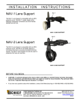
INSTALLATION
INSTRUCTIONS
Projector
Lock (PL-1)
The PL-1 projector lock, constructed with heavy gauge
steel, is designed to prevent access to projector mounts.
The projector lock protects against disconnecting
projectors from their mounts in most high-risk
environments, minimizing the probabilities theft.
The design of the PL-1 ensures proper ventilation for
your projector while providing excellent security and
protection.
PL-1
BEFORE YOU BEGIN
•
CAUTION: To prevent damage to your display, which could affect or void the Factory warranty,
thoroughly study all instructions and illustrations before you begin to install the mount brackets. Pay
particular attention to the “Important Warnings and Cautions” on Page 2.
•
If you have any questions about this installation, contact Chief Manufacturing.
Chief® is a registered trademark of Milestone AV Technologies. All rights reserved.
8803-000065 Rev C
Chief Manufacturing, a division of Milestone AV Technologies
©2008 Milestone AV Technologies
8401 Eagle Creek Parkway, Savage, MN 55378
05/08
P: 800.582.6480 / 952.894.6280 F: 877.894.6918 / 952.894.6918
Installation Instructions
PL-1
IMPORTANT WARNINGS and CAUTIONS!
WARNING
A WARNING alerts you to the possibility of serious injury or death if you do not follow
the instructions.
CAUTION
A CAUTION alerts you to the possibility of damage or destruction of equipment if you do not
follow the corresponding instructions.
•
WARNING
Improper installation can result in serious personal injury! Make sure that the
mounting surface can support a redundant weight factor five times the total weight of
the equipment. If not, reinforce the mounting surface structural members before
installing the mount.
•
WARNING
Make sure the mount is correctly oriented.
•
CAUTION
Check the unit for shipping damage before you begin the installation.
DIMENSIONAL DRAWING
2
Installation Instructions
PL-1
CONTENTS
PARTS LIST
DIMENSIONAL DRAWING ............................................... 2
TOOLS REQUIRED FOR INSTALLATION ....................... 3
PARTS LIST ...................................................................... 3
INSPECT INSTALLATION LOCATION............................. 3
INSTALLATION ................................................................. 4
Prior to assembly, unpack the carton completely. Verify
contents listed in Table 1.
Read installation instructions completely. If you are
missing any of the listed parts, contact Customer Service
at: 1-800/582-6480.
Table 1. Parts List
TOOLS REQUIRED FOR
INSTALLATION
•
Allen wrench set
NOTE: Other tools may be required depending on your
method of installation.
REF
DESCRIPTION
QTY
10
PL-1 Projector Lock
1
20
Screws
4
30
Spacers
4
PL1A*
Key C346A
OR
2
PL1B*
Key C346B
OR
2
PL1C*
Key C346C
2
*The PL-1 is shipped with two matching keys: PL1A, or
PL1B, or PL1C. To ensure security, the PL-1 is shipped
with one of three different keys.
INSPECT INSTALLATION
LOCATION
Because of the wide variety of possible mounting
situations, Chief Manufacturing only provides general
guidelines for the typical pole-mounted installation.
Study the following information carefully, and make
adjustments as necessary to fit your specific installation.
WARNING
There is a potential for personal injury or equipment
damage if the projector is not adequately mounted.
Be aware of the overall weight of the equipment,
including weight of projector and all attaching
hardware.
3
Installation Instructions
PL-1
INSTALLATION
This manual contains installation procedures that cover
pole-mounted applications:
NOTE: Omit Step1 thru 3 and proceed to Step 4 if the
projector is already installed on the 1-1/2” NPT pipe.
Set Screw
Key Lock
1. If projector is mounted, remove projector and SLB.
2. Loosen the thumbnuts and disconnect your projector
from the RPA.
3. Install the RPA mount on the 1-1/2” NPT pipe as
described in the instructions for your RPA mount.
Figure 1. Align Set Screw & Key Lock
4. Unlock and open the PL-1.
5. Align set screw of RPA with key lock of cage (see
Figure 1).
6. Tilt the lock side of the PL-1 down and route the RPA
thru the hole in the PL-1 (see Figure 2).
7. Set PL-1 on RPA (see Figure 3).
Figure 2. Place PL-1 on RPA
Figure 3. PL-1 on RPA
4
Installation Instructions
PL-1
INSTALLATION (CONT’D)
8. Install the projector (see Figure 4).
9. Tightening the center thumb screw first, make sure
all thumb screws are tight.
5
Installation Instructions
PL-1
INSTALLATION (CONT’D)
10. Route the cables (Figure 5).
11. Slide PL-1 halves together (see
Figure 6).
12. Insert key.
13. To operate the lock, do the following:
a.
To lock the PL-1, turn the key (supplied) 90°
clockwise.
b.
To unlock the PL-1, turn the key (supplied) 90°
counterclockwise.
14. Remove key.
Figure 4. Install Projector
Side Cable
Route Access
Cable Route Access
Side Cable
Route Access
Figure 5. Route Cables
Unlock (CCW)
90°
Lock (CW)
Figure 6. Lock Unit
6
Installation Instructions
PL-1
7
Installation Instructions
8
PL-1