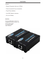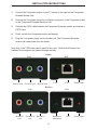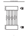
1
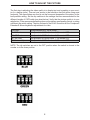
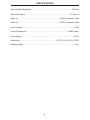
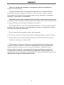
Component
Extender
USER
MANUAL
www.gefen.com
ASKING FOR ASSISTANCE
Technical Support:
Telephone
(818) 772-9100
(800) 545-6900
Fax
(818) 772-9120
Technical Support Hours:
8:00 AM to 5:00 PM Monday thru Friday.
Write To:
Gefen Inc.
C/O Customer Service
20600 Nordhoff St.
Chatsworth, CA 91311
Notice
Gefen Inc. reserves the right to make changes in the hardware, packaging and any
accompanying documentation without prior written notice.
Component Extender is a trademark of Gefen Inc.
© 2007 Gefen Inc., All Rights Reserved
TABLE OF CONTENTS
1
INTRODUCTION
2
FEATURES
3
INSTALLATION INSTRUCTIONS
4
CAT5 WIRING DIAGRAM
5
HOW TO ADJUST THE PICTURE
6
SPECIFICATIONS
7
WARRANTY
INTRODUCTION
Thank you for purchasing the Component Extender by Gefen, Inc.
The Component Extender allows users to extend Component video signals beyond the
A/V rack. The Component Extender Series can be used to extend a Component signal to
cover the distances up to 330 feet. Industry standard Category 5e (CAT-5e) cable is used
for the extension.
HOW IT WORKS
The Component Extender sender resides next to the TV source. With the supplied
Component cable, the Component Extender sender is connected to the source. The
Component Extender receiver is then placed next to the monitor or projector. Industry
standard Category 5e (CAT-5e) cable is used to link the Component Extender sender and
Component Extender receiver together.
OPERATION NOTES
READ THESE NOTES BEFORE INSTALLING
OR OPERATING THE COMPONENT EXTENDER SYSTEM
• Use industry standard Category-5e (CAT-5e) cable to operate the Component Extender
system. CAT-5e cable is preferred.
• Please connect all the cables between the source and the Component Extender before
powering up the Component Extender unit.
• The Component Extender units are housed in a metal box for better RF shielding.
1
FEATURES
Features
• Extends Component video up to 330 feet
• Power only required only on transmitter.
• Plug & Play installation.
• One CAT5 Cable for extension.
• No Loss of Quality.
Includes:
Component Extender sender unit
Component Extender receiver unit
5V DC power supply
Component Cable
User’s Manual
2
INSTALLATION INSTRUCTIONS
1.
Connect the Component output of your TV source to the input on the Component
Extender Sender Unit.
2.
Connect the Component input of your display or projector to the Component output
on the Component Extender Receiver Unit.
3.
Connect the CAT-5 cable between the Component Extender sender and receiver’s
CAT-5 input.
4.
Power on both the Component source and display
5.
Plug the 5 volt power supply into the sender unit. The Component Extender
receiver will draw power from the sender.
Note: Any of the 3 RCA lines can be used for any color. Both ends will need to be
matched for the signal to be passed through correctly.
Sender
Front
Red RCA In
Green RCA In
Back
5V DC
Blue RCA In
Cat 5
Power Light
Receiver
Front
Red RCA
Out
Green RCA
Out
Back
Brightness
Adjustment
Blue RCA
Out
3
Cat 5
Power Light
4
1
8
8
7
6
5
4
3
2
1
RJ-45 Jack
Brown
White/Brown
Green
White/Blue
Blue
White/Green
Orange
White/Orange
8
7
6
5
4
3
2
1
1
8
RJ-45 Jack
CAT5 WIRING DIAGRAM
HOW TO ADJUST THE PICTURE
The first step in adjusting the video quality is to display text and a graphic on your monitor (i.e. desktop icons). Then set your source to the resolution that you will be using most
frequently. The dip switches are used to set the focus and sharpness of the picture to the
best possible setting. Set the dip switches to the settings that are recommended for the
different lengths of CAT5 cable (see chart below). Verify that the picture quality is to your
satisfaction. If the recommended setting does not produce a great quality picture, try using
a different dip switch setting. The trim pod next to the RJ-45 connector on the Component
Extender-S allows brightness adjustments for video.
0-25 Feet
26-100 Feet
101-200 Feet
201-300 Feet
301 Feet and Up
All dip switches OFF for all colors.
Set dip switch #1 ON all colors. 2,3,4 remain OFF.
Set dip switch #2 ON all colors. 1,3,4 remain OFF.
Set dip switch #3 ON all colors. 1,2,4 remain OFF.
Set dip switch #4 ON all colors. 1,2,3 remain OFF.
NOTE: The dip switches are set to the OFF position when the switch is closest to the
number or in the down position.
5
SPECIFICATIONS
Video Amplifier Bandwidth .................................................................................. 350 MHz
Input Video Signal ......................................................................................... 1.2 Volts p-p
Video In ..................................................................................... 3 RCA Component Video
Video out .................................................................................. 3 RCA Component Video
Link Connector ........................................................................................................ RJ-45
Power Consumption .................................................................................. 5 Watts (max.)
Power Supply ......................................................................................................... 5V DC
Dimensions .......................................................................... 0.875”H x 1.625”W x 3.25”D
Shipping Weight ....................................................................................................... 3 lbs.
6
WARRANTY
Gefen Inc. warrants the equipment it manufactures to be free from defects in
material and workmanship.
If equipment fails because of such defects and Gefen Inc. is notified within two
(2) year from the date of shipment, Gefen Inc. will, at its option, repair or replace
the equipment, provided that the equipment has not been subjected to mechanical,
electrical, or other abuse or modifications.
Equipment that fails under conditions other than those covered will be repaired at the
current price of parts and labor in effect at the time of repair. Such repairs are warranted
for ninety (90) days from the day of reshipment to the Buyer.
This warranty is in lieu of all other warranties expressed or implied, including without
limitation, any implied warranty or merchantability or fitness for any particular purpose,
all of which are expressly disclaimed.
1. Proof of sale may be required in order to claim warranty.
2. Customers outside the US are responsible for shipping charges to and from Gefen.
3. Copper cables are limited to a 30 day warranty and cable must be free from any
scratches, markings, and neatly coiled.
The information in this manual has been carefully checked and is believed to be
accurate. However, Gefen Inc. assumes no responsibility for any inaccuracies that
may be contained in this manual. In no event will Gefen Inc., be liable for direct,
indirect, special, incidental, or consequential damages resulting from any defect
or omission in this manual, even if advised of the possibility of such damages. The
technical information contained herein regarding the Component Extender features and
specifications is subject to change without notice.
7