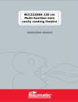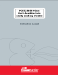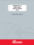
1
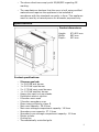
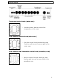
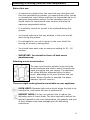
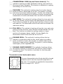
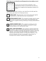
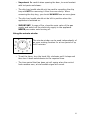
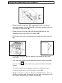
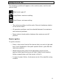
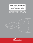
BT2740SS 90cm Multifunction twin cavity
cooking theatre
1
User Manual for your Baumatic
BT2740SS
90 cm Multi-function twin cavity cooking
theatre
NOTE: This User Instruction Manual contains important
information, including safety & installation points, which will
enable you to get the most out of your appliance. Please keep it
in a safe place so that it is easily available for future reference; for
you or any person not familiar with the operation of the appliance.
DD 19/12/06
2
Contents
Environmental note
4
Important safety information
5–9
Specifications
9 – 10
Control panel
Thermostat control knob (main oven)
Oven function selector knob (main oven)
Oven function and thermostat control knob (secondary oven)
11
11
11
11
Selecting a cooking function and temperature
Before first use
Selecting a main oven function
Thermostat control knob (main oven)
Selecting an oven function and temperature (secondary oven)
Cooking guidelines
Warnings
Using the minute minder
Using and assembling the rotisserie
Using the hob top
Electric ignition
Energy saving tips
12
12
12-13
13
14
15
15-16
16
17
18
18
19
Cleaning and maintenance
Cleaning the hob burners
Replacing the oven bulb
Removing the oven door for cleaning
Removing the inner door glass for cleaning
20
21
21
22
22-23
Installation
Positioning
Gas connection
Gas Safety (Installation and Use) Regulations
Gas connection
Gas adjustment (Conversion to LPG and flow adjustment)
Minimum flow adjustment for hob gas taps
Fitting a stability chain
Electrical connection
Connecting the mains supply cable
Replacing the mains supply cable
23
23-25
25-26
26
27
28-29
29
30
31
31–32
32
My appliance isn’t working correctly
33-34
Baumatic Ltd. Conditions of guarantee
35
Contact details
36
3
Environmental note
o The packaging materials that Baumatic uses are environmentally
friendly and can be recycled.
o Please discard all packaging material with due regard for the
environment.
4
Important safety information
Your safety is of the utmost importance to Baumatic.
Please make sure that you read this instruction booklet
before attempting to install or use the appliance. If you
are unsure of any of the information contained in this
booklet, please contact the Baumatic Technical
Department.
General Information
o This appliance is designed for domestic household use and for
the cooking of domestic foodstuffs.
o IMPORTANT: The adjacent furniture and all materials used in
the installation must be able to withstand a minimum
temperature of 85°C above the ambient temperature of the
room it is located in, whilst in use.
o Certain types of vinyl or laminate kitchen furniture are
particularly prone to heat damage or discolouration at
temperatures below the guidelines given above.
o Any damage caused by the appliance being installed in
contravention of this temperature limit, or by placing adjacent
cabinet materials closer than 20 mm to the appliance, will be
the liability of the owner.
o For use in leisure accommodation vehicles, please refer to
the appropriate information given in the installation instructions
for this appliance.
o IMPORTANT: Baumatic Ltd. DO NOT recommend that this
appliance is installed on any type of marine vessel.
o The use of this appliance for any other purpose or in any other
environment without the express agreement of Baumatic Ltd.
will invalidate any warranty or liability claim.
o Your new appliance is guaranteed against electrical or
mechanical defects, subject to certain exclusions that are noted
in Baumatic’s Conditions Of Guarantee. The foregoing does not
affect your statutory rights.
o Repairs may only be carried out by Baumatic Service
Engineers or their authorised service agent.
5
Warning and safety instructions
o This appliance complies with all current European safety
legislation. Baumatic do wish to emphasise that this compliance
does not remove the fact that the appliance surfaces will
become hot during use and retain heat after operation.
Child Safety
o Baumatic strongly recommend that babies and young children
are prevented from being near to the appliance and not allowed
to touch the appliance at any time. During and after use, all
surfaces will become hot.
o If it is necessary for younger family members to be in the
kitchen, please ensure that they are kept under close supervision
at all times.
General Safety
Make sure that you understand the controls before using the
appliance.
Check that all of the controls on the appliance are turned off
after use.
Always stand back when opening the oven door, this will allow
heat to disperse.
Take care when removing items from the oven, as the contents
may be hot.
Always keep the oven doors closed when the oven is not in use.
Always follow the basic principles of food handling and hygiene,
this will prevent the possibility of bacterial growth.
Always keep ventilation slots clear of obstructions.
Keep fingers away from the hinge areas when closing the door,
otherwise you may trap them.
Oven gloves should be used when placing food in the oven cavity
and when removing it. Care should be taken to avoid direct
contact with any of the elements in the appliance.
o DO NOT LEAVE THE APPLIANCE UNATTENDED WHILST IN
USE.
6
o Do not place heavy objects on the oven door or lean on the
oven door when it is open, as this can cause damage to the oven
door hinges. Nobody should be allowed to sit or stand on any
part of the cooker.
o Do not store chemicals, food stuffs, pressurised containers in or
on the cooker or in the cabinets immediately above or near the
hob burners.
o Do not heat up unopened food containers, as pressure can build
up which may cause the container to burst.
o Do not place flammable or plastic items on or near the hob
burners, these types of materials should also not be placed in
the oven or the compartment below the oven.
o Do not leave heated oil or fat unattended, as this is a fire risk.
You should not fill a deep fat frying pan more than one third full
of fat or oil, you should also not use a lid.
o Do not allow fat or oil to build up in the oven trays, grill pan or
oven base.
o Do not place pans or baking trays directly on the base of the
oven cavity, or line it with aluminium foil.
o Do not grill food containing fat without using the grill trivet. The
grill trivet should never be covered with aluminium foil.
o Do not place hot enamel parts in water, leave them to cool first.
o Do not allow vinegar, coffee, milk, saltwater, lemon, tomato
juice or any liquid with high sugar content to remain in contact
with the enamel parts of the appliance. Spillages should be
wiped up immediately.
o Do not allow electrical fittings or cables to come into contact
with areas on the appliance that get hot.
o Do not use the appliance to heat the room it is located in or to
dry clothing. No clothing should be placed over or near to the
hob burners or oven door.
o Do not install the appliance next to curtains or soft furnishings.
7
o Do not attempt to lift or move cooking appliances by using the
oven door or handle, as this may cause damage to the appliance
or result in injury to the person lifting the appliance.
o Do not store chemicals, food stuffs, pressurised containers in or
on the cooker or in cabinets immediately above or next to the
cooker.
Cleaning
o Cleaning of the oven should be carried out on a regular basis.
o Great care should be taken whilst using this appliance and when
following the cleaning procedure.
o IMPORTANT: The appliance must be disconnected from the
mains before following the cleaning procedure.
Installation
This appliance must be correctly installed by a
suitably qualified person, strictly in accordance
with the manufacturer’s instructions. Please see
the specific section of this booklet that refer to
installation.
o Baumatic Ltd. declines any responsibility for injury or
damage, to person or property, as a result of improper
use or installation of this appliance.
o Heat, steam and moisture will be created during use of the
appliance, take care to avoid injury and ensure that the room is
adequately ventilated. If the appliance is going to be used for
prolonged periods of time, then additional ventilation may be
required.
o Please consult with your qualified installer if you are in any doubt
about the amount of ventilation that you will require.
Declaration of conformity
This appliance complies with the following European Directives:
-73/23/EEC
regarding “low voltage”
-89/336/EEC regarding “electromagnetic disturbances”
-90/396/EEC regarding “gas appliances”
-89/109/EEC regarding “materials in contact with food”.
8
o The above directives comply with 93/68/EEC regarding CE
marking.
o The manufacturer declares that the oven is built using certified
materials and requires the appliance to be installed in
accordance with the standards currently in force. This appliance
must be used by a trained person for domestic purposes only.
Specifications
Product dimensions:
Height:
Width:
Depth:
870-920 mm
895 mm
600 mm
Product specifications:
o
o
o
o
o
o
o
o
o
o
o
o
o
o
o
o
o
5 burner gas hob:
1 x 3.60 kW wok burner
1 x 3.00 kW rapid burner
2 x 1.75 kW semi-rapid burners
1 x 1.00 kW auxillary burner
Heavy duty cast iron pan stands
Pushbutton electric ignition
8 function main oven
5 function secondary oven
Oven energy efficiency class: B
Main oven capacity: 59.4 litres
Main oven storage compartment capacity: 18 litres
Secondary oven capacity: 37.1 litres
Secondary oven storage compartment capacity: 10 litres
Minute minder
Cooling fan
Thermostatically controlled grills
9
o Double glazed removable doors
o Adjustable feet
Standard accessories:
o
o
o
o
o
o
o
Wok stand
3 x Safety shelves
2 x Enamelled drip trays with handle
2 x Trivets
Rotisserie rack
Rotisserie skewer with removable handle
LPG conversion jets
Optional extras:
o BPS1 Pizza stone
o BTGRID Double-sided griddle plate
Electrical details
Rated Voltage:
Supply Connection:
Max Rated Inputs:
Mains Supply Lead:
Oven Light Bulb:
230 Vac 50 Hz
20 A (double pole switched fused
outlet with 3mm contact gap)
3.8 kW
3 core x 2.5 mm² (not supplied)
E14 25 W/300°C screw type pigmy
Gas details
Gas Connection Type:
Gas Type (Natural Gas):
Gas Type (LPG):
1/2” BSP
20 mbar
See table on page 28 for this
information.
For future reference please record the following information which can
be found on the rating plate and the date of purchase which can be
found on your sales invoice. The rating plate for your oven can be
located by opening the door of the storage compartment.
Model Number
……………………………….
Serial Number
……………………………….
Date of Purchase
……………………………….
10
Control Panel
Thermostat control knob (main oven)
o Use this control knob to control the
temperature in the oven.
Oven function selector knob (main oven)
o Use this control knob to select the oven
function and turn on the oven light in the
main oven.
Oven function and thermostat control knob (secondary oven)
o Use this control knob to select the oven
function and turn on the oven light in the
secondary oven.
11
Selecting a cooking function and temperature
Before first use
o To remove any residue from the oven that may have been left
from the manufacturing process, you should select either the fan
or conventional oven function and turn the thermostat dial to its
maximum temperature setting. For the secondary oven you
should select the conventional oven function and select its
maximum temperature setting.
o It is perfectly normal for a smell to be produced during this
process.
o You should make sure that any windows in the room are left
open during this process.
o It is advisable for you not to remain in the room whilst the
burning off process is taking place.
o You should leave each oven on maximum setting for 30 – 40
minutes.
o IMPORTANT: You should not burn off both ovens
simultaneously.
Selecting a main oven function
The main oven function selector knob should be
turned clockwise and used to select the particular
mode of cooking that you require. The appliance
will utilise different elements within the oven
cavity, depending on the oven function that you
select. When a function is selected, the power
indicator light will come on.
There are eight cooking functions available on your appliance:
OVEN LIGHT: Separate light control which allows the light to be
switched on, even when the oven is switched off.
DEFROST MODE: The fan runs without heat to reduce the
defrosting time of frozen foods. The time required to defrost the
food will depend on the room temperature, the quantity and type
of food. Always check food packaging for the defrosting
instructions.
12
CONVENTIONAL OVEN (top and lower element): This
method of cooking provides traditional cooking, with heat from
the top and lower elements. This function is suitable for roasting
and baking on one shelf only.
FAN OVEN: This method of cooking uses the circular element
while the heat is distributed by the fan. This results in a faster
and more economical cooking process. The fan oven allows food
to be cooked simultaneously on different shelves, preventing the
transmission of smells and tastes from one dish onto another.
HALF GRILL: This method of cooking utilises the inner part only
of the top element, which directs heat downwards onto the food.
This function is suitable for grilling small portions of bacon, toast
and meat etc. The thermostat control knob must be turned to its
maximum setting.
FULL GRILL: This method of cooking utilises the inner and outer
parts of the top element, which directs heat downwards onto the
food. This function is suitable for grilling medium or large
portions of sausages, bacon, steaks, fish etc. Ideally the
thermostat control knob should be set to 200°C
FAN AND GRILL: This method of cooking utilises the top
element in conjunction with the fan, which helps to provide a
quick circulation of heat. This function is suitable where quick
browning is required and “sealing” the juices in, such as steaks,
hamburgers, some vegetables etc.
FAN AND LOWER ELEMENT: This method of cooking utilises
the bottom element in conjunction with the fan, which helps to
circulate the heat. This function is suitable for sterilising and
preserving jars.
Thermostat control knob (main oven)
The oven thermostat control knob should be turned
clockwise and it sets the required temperature of
the oven. It is possible to regulate the temperature
within a range of 60 - 250°C.
13
Selecting an oven function and temperature (secondary oven)
If you turn the control knob clockwise, it will
automatically select a conventional oven function
and you can regulate the temperature between 60 250°C.
To use one of the other functions, you should turn the dial past the
max. setting and select the following functions.
OVEN LIGHT: Separate light control which allows the light to
be switched on, even when the oven is switched off.
UPPER ELEMENT ONLY: This method of cooking uses the outer
part of the top element to direct gentle heat downwards onto
the food. For gentle cooking, browning or keeping cooked dishes
warm.
LOWER ELEMENT ONLY: This method of cooking uses the
lower element to direct heat upwards to the food. For slowcooking recipes or for warming up meals.
GRILL AND ROTISSERIE: This method of cooking utilises the
top element, which directs heat downwards onto the food. This
function is suitable for grilling small portions of bacon, toast and
meat etc. This function will also operate the rotisserie if it is
inserted (see separate section on “Using the rotisserie”). The
grill and rotisserie will give a moderate to strong heat. For
cooking whole chickens, kebabs and fast roasting.
14
Cooking guidelines
o Please refer to the information given on food packaging for
guidance on cooking temperatures and times. Once familiar with
the performance of your appliance, temperatures and times can
be varied to suit personal preference.
o If you are using the fan oven function, then you should follow
the information given on the food packaging for this particular
mode of cooking.
o Make sure that frozen foods are thoroughly thawed before
cooking, unless the instructions on the food packaging advise
that you can “cook from frozen”.
o You should pre-heat the oven and not place food inside of it until
the oven operating light has gone off. You can choose not to preheat when using the fan oven mode; however you should extend
the cooking time given on the food packaging by approximately
ten minutes.
o Before cooking, check that any unused accessories are removed
from the oven.
o Place cooking trays in the centre of the oven and leave gaps
between the trays to allow air to circulate.
o Try to open the door as little as possible to view the dishes.
o The oven light will remain on during cooking.
Warnings
o Keep the main oven door closed when using any of the grill or
oven functions.
o Do not use aluminium foil to cover the grill pan or heat items
wrapped in aluminium foil under the grill. The high reflectivity of
the foil could potentially damage the grill element.
o You should never line the base of your oven with aluminium foil.
o During cooking, never place pans or cookware directly onto the
bottom of the oven. They should always be placed on the shelves
provided.
o The grill heating element becomes extremely hot during
operation, avoid touching it inadvertently when handling the
food which you are grilling.
15
o Important: Be careful when opening the door, to avoid contact
with hot parts and steam.
o The drip tray handle should only be used to reposition the drip
tray and NOT for removing it from the oven cavity. When
removing the drip tray, you should ALWAYS use an oven glove.
o The drip tray handle should not be left in position when the
appliance is switched on.
o IMPORTANT: In case of fire, close the main valve of the gas
supply and switch off the electricity supply to the appliance.
NEVER pour water onto burning oil.
Using the minute minder
The minute minder can be used independently of
an oven cooking function for a time period of up
to 60 minutes.
o To set the timer, turn the knob fully clockwise until it stops and
then turn it back anticlockwise to the required time.
o The time period that has been set will expire when the control
knob reaches zero, a brief audible signal will sound.
16
Using and assembling the rotisserie
o Place the food on the spit (L), making sure that it is placed
centrally between the two forks (F). Otherwise excess strain will
be placed on the motor (R).
o Place one end of the spit (L) onto support (G) and put the
opposite end into the hole of the motor (P).
o Fill the drip tray with a little water and place this under the spit
(L).
o Fit the grill deflector (S) into position and leave the door half
way open.
o Turn the Oven function and thermostat control knob (secondary
oven) to the
button.
symbol and then press the Rotisserie On/Off
o To rotate the spit in the opposite direction, whilst wearing a
protective oven glove, turn the rotation knob (A).
o Make sure that you press the Rotisserie On/Off button, then turn
the Oven function and thermostat control knob (secondary oven)
to 0 before attempting to remove the spit (L).
17
Using the hob top
The following symbols will appear on the control panel, next to each
control knob:
Black circle: gas off
Large flame: maximum setting
Small flame: minimum setting
o The minimum setting is at the end of the anti-clockwise rotation
of the control knob.
o All operation positions must be selected between the maximum
and minimum positions.
o Never select a knob position between the maximum and off
position.
Electric ignition
To ignite a burner:
o Press in the control knob of the burner that you wish to light and
turn it anti-clockwise to the spark symbol which is just after the
maximum position.
o Whilst keeping the control knob depressed, press the hob
ignition button and the burner will light. Keep the hob ignition
button pressed down until the burner is fully lit.
o In case of power failure, the burners can be lit by carefully using
a match.
18
Energy saving tips
o The diametre of the bottom of the pan should correspond to that
of the burner.
o The burner flame must never extend beyond the diametre of the
pan.
o Use flat bottomed pans only
o When possible, keep a lid on the pan whilst cooking.
o Cook vegetables with as little water as possible, to reduce
cooking times.
IMPORTANT: Always place pans centrally over the hob burners and
position them so that the handles cannot get accidentally caught or
knocked off. You should also make sure that the handle is not over one
of the other hob burner flames.
19
Cleaning and maintenance
Cleaning operations must only be carried out
when the oven is cool.
The appliance should be disconnected from your
mains supply before commencing any cleaning
process.
o The oven should be thoroughly cleaned before it is operated for
the first time and after each use. This will avoid residual food
stuffs becoming baked on the oven cavity. After residues have
been baked on several times, they are far more difficult to
remove.
o Never clean the oven surfaces by steam cleaning.
o The oven cavity should only be cleaned with warm soapy water,
using either a sponge or soft cloth. No abrasive cleaners should
be used.
o Any stains that may appear on the bottom of the oven will have
originated from food splashes or spilt food, these splashes occur
during the cooking process. These could possibly be a result of
the food being cooked at an excessively high temperature or
being placed in cookware that is too small.
o You should select a cooking temperature and function that is
appropriate for the food that you are cooking. You should also
ensure that the food is placed in an adequately sized dish and
that you use the drip tray where appropriate.
o Outer parts of the oven should only be cleaned with warm soapy
water, using either a sponge or soft cloth. No abrasive cleaners
should be used.
o If you use any form of oven cleaner on your appliance, then you
must check with the manufacturer of the cleaner that it is
suitable for use on your appliance.
o Any damage that is caused to the appliance by a cleaning
product will not be fixed by Baumatic free of charge, even
if the appliance is within the guarantee period.
20
Cleaning the hob burners
The hob burners should be cleaned once a week or more frequently if
they get soiled.
o Remove the hob burners by pulling them upwards and away
from the hob top.
o Soak them for about ten minutes in hot water and a little
detergent.
o After cleaning and washing them, wipe and dry them carefully.
o Before placing the burners back on the hob top, make sure that
the gas jet is not blocked.
o IMPORTANT: Make sure that you reassemble the burners in the
original way.
Replacing the oven bulb
IMPORTANT: The oven must be disconnected from
your mains supply before you attempt to either
remove or replace the oven bulb.
o Remove all oven shelves,
and the drip tray.
o Unscrew the lamp cover.
o Unscrew the bulb and
remove it from its holder.
o Replace the bulb with a 25 W/300°C, screw type pigmy.
o Do not use any other type of bulb.
o Screw the lamp cover back into its original position.
21
Removing the oven door for cleaning
o Open the oven door fully.
o The hinges (A) are provided with two movable hooks (B).
o Rotate the hooks into the slot (C).
o You should grip the sides of the door at the centre and then
incline it slightly towards the oven cavity and then by pulling it
gently away from the oven cavity.
o IMPORTANT: You should make sure that the door is supported
at all times and that you place the door on some padded
material whilst cleaning it.
o The oven door and door glass should only be cleaned using a
damp cloth and a small amount of detergent. The cloth MUST
NOT have come into contact with any form of cleaning product
or chemical previously.
o Replace the oven door by introducing the hinges back into their
relevant slots. Before closing the doors DO NOT FORGET TO
RESET THE MOVABLE HOOKS.
o DO NOT attempt to move the hooks whilst the door is not
attached to the oven, as the hinges are under high spring
tension and injury may result.
Removing the inner door glass for cleaning
o Do not use any abrasive cleaner that could cause damage.
o Remember that if the surface of the glass panel becomes
scratched, this could lead to a dangerous failure.
o To facilitate cleaning, the door glass can be lifted out after
removing the fixing screws and turning the metal stoppers that
hold the glass in position.
22
o When refitting, make sure that the glass is correctly seated in
the door recess and the correct way round, before turning the
metal stoppers back to their original position and fully tightening
the fixing screws.
Installation
The installation must be carried out by a suitably
qualified person, in accordance with the current
version of the following.
o UK Regulations and Safety Standards or their European
Norm Replacements.
o Building Regulations (issued by the Department of the
Environment).
o Building Standards (issued by the Scottish Development
Department).
o IEE Wiring Regulations.
o Electricity At Work Regulations.
o Gas Safety (Installation and Use) (Amendment)
Regulations.
Positioning
The adjacent furniture and all materials used in the
installation must be able to withstand a minimum
temperature of 85°C above the ambient
temperature of the room it is located in, whilst in
use.
o Your appliance is heavy, so you should be careful when moving
or positioning it.
o Do not try to move the cooker by pulling on either the door,
handle or control panel.
23
o The cooker is designed to slot in between 600 mm deep
cabinets, which are spaced approximately 940 mm apart.
o It can also be used as freestanding, with a cabinet to one side, in
a corner setting or with its back to a wall.
o IMPORTANT: It must not be situated with either side
closer than 20 mm to a combustible wall or cupboard that
is taller than the cooker. It should not be installed at the end
of a run of cabinets, if there is a cabinet at immediate right
angles to the cooker door.
o The wall behind the cooker and 450 mm above and across the
width of the cooker should be an incombustible material and
preferably an easy clean surface, such as ceramic tiles.
o Any overhanging surface or cooker hood should be at least 700
mm above the hob top.
o Baumatic do not recommend that the cooker is positioned below
wall cupboards, as the heat and steam from the appliance and
what is being cooked, may damage the cupboard and its
contents.
o The cooker may be located in a kitchen, or a bedroom, but not in
a room containing a bath or shower. The cooker must not be
installed in a bedroom of less than 20m³ in size.
o LPG models must not be installed in a room or internal space
below ground level (e.g. in a basement).
o The cooker is fitted with four legs that can be adjusted to match
the height of your kitchen cabinets.
o To assemble them it is necessary to raise the cooker and to
screw the four legs into position, on each corner of the base of
the appliance.
24
o IMPORTANT: They must be screwed clockwise into position and
not just slotted into the holes on each corner.
Gas connection
This appliance must be installed by a competent
person in accordance with the current versions of
the following UK (United Kingdom) or ROI (Republic
of Ireland) Regulations and Safety Standards or
their European Norm Replacements.
Important information
o This cooker is supplied to run on natural gas only and cannot
be used on any other type of gas without modification.
o Conversion for use on LPG and other gases must only be
undertaken by a qualified person. For information on the use of
other gases, please contact the Baumatic Technical Department.
o The cooker must be installed by a qualified person, in
accordance with the current edition of the Gas Safety
(Installation and Use) (Amendment) Regulations and the
relevant building/I.E.E. Regulations.
o Failure to install the appliance correctly could invalidate
Baumatic’s guarantee and lead to prosecution under the
regulations quoted above.
o In the UK, CORGI registered installers are authorised to
undertake the installation and service work, in compliance with
the above regulations.
Ventilation requirements
o The room containing the cooker should have an air supply in
accordance with the current edition of BS 5440: Part 2:
o The room must have opening windows or equivalent; some
rooms may also require a permanent vent.
o If the room has a volume between 5 and 10m³, it will require an
air vent of 50cm² (effective area). Unless it has a door which
opens directly to the outside.
o If the room has a volume of less than 5m³, it will require an air
vent of 100cm² (effective area).
25
o If there are any other fuel burning appliances in the same room
the current edition of BS 5440: Part 2: should be consulted to
determine air vent requirements.
o Ensure that the room containing the cooker is well ventilated,
keep natural ventilation holes or install a mechanical ventilation
device (mechanical cooker hood).
o Prolonged intensive use of the appliance may call for additional
ventilation, either by the opening of a window, or by increasing
the level of the mechanical ventilation device (where present).
o This cooker is not fitted with a device for discharging the
products of combustion. Ensure that the ventilation rules and
regulations are followed.
o Excess steam from the oven, vents out at the top back edge of
the cooker, so make sure that the walls behind and near the
cooker are resistant to heat, steam and condensation.
o Your cooker must stand on a flat surface so that when it is in
position the hob is level. When in position check that the cooker
is level by using a spirit level and adjust the 2 feet at the rear
and the 2 feet at the front if necessary.
o Remember that the quantity of air necessary for combustion
must never be less than 2m³/h for each kW of power (see total
power in kW on the appliance rating plate).
Gas Safety (Installation and Use) Regulations
o It is the law that all gas appliances are installed by competent
persons in accordance with the current edition of the Gas Safety
Installation and Use Regulations.
o It is in your interest and that of safety to ensure compliance with
the law.
o In the UK, CORGI registered installers work to safe standards of
practice. The cooker must also be installed in accordance with
the current edition of BS 6172. Failure to install the cooker
correctly could invalidate the warranty, liability claims and lead
to prosecution.
o IMPORTANT: It is a requirement for a stability chain to be
fitted to the appliance. Please see page 30 for more
detailed information on this.
26
Gas connection
ALL INSTALLATION AND SERVICE WORK MUST BE
CARRIED OUT BY A CORGI REGISTERED ENGINEER.
o Prior to installation, ensure that the gas supply conditions
(nature of the gas and gas pressure) and the adjustment
conditions are compatible. The adjustment conditions for this
appliance are stated on the rating plate which can be found on
the back cover.
o This appliance is not designed to be connected to a combustion
product evacuation device. Particular attention should be given
to the relevant requirements regarding ventilation.
o Connection to the cooker should be made with an approved
appliance flexible connection to BS 669.
o If the cooker has been converted for use with LPG, then it should
be connected to the gas supply using a bayonet type hose. The
hose MUST be suitable for use with LPG gas. They are
identifiable by a red band or stripe.
o A hose length of 0.9m to 1.25m is recommended. The length of
hose chosen should be such that when the cooker is in situ, the
hose does not touch the floor.
o Care should be taken to ensure that the temperature rise of
areas at the rear of the cooker that are likely to come in contact
with the flexible hose do not exceed 70°C.
o Gas pressure may be checked on a semi-rapid hob burner.
Remove the appropriate injector and attach a test nipple. Light
the other burners and observe that the gas pressure complies
with the gas standards in force.
o This cooker can be connected to the supply both on the right and
left hand side at the rear of the cooker. To reverse the position,
remove the blanking plug and refit it to the opposite side to
where the hose is being connected.
o IMPORTANT: On completion carry out a gas tightness test.
27
Gas adjustment (Conversion to LPG and flow adjustment)
All work must be carried out by a CORGI registered
engineer.
IMPORTANT: Always isolate the cooker from the electricity
supply before changing the injectors and/or adjusting the
minimum flow of the burners.
o Remove the pan-stands, burners and
flame spreaders (A).
o Unscrew the injector (B) and replace it
with the stipulated injector for the new gas
supply (see table below).
BURNER
GAS
PRESSURE
(mbar)
INJECTOR
DIAMETRE
1/100mm
GAS
CONSUMPTION
POWER
(kW)
Max Min
Auxiliary
Liquid gas- G30
G31
Nat. gas- G20/G25
Town gas- G110
G120
Liquid gas- G30
G31
Nat. gas- G20/G25
Town gas- G110
G120
Liquid gas- G30
G31
Nat. gas- G20/G25
Town gas- G110
G120
Liquid gas- G30
G31
Nat. gas- G20/G25
Town gas- G110
G120
28 – 30
37
20/25
8
8
28 – 30
37
20/25
8
8
28 – 30
37
20/25
8
8
28 – 30
37
20/25
8
8
50
73 gr/h
1
0.3
70
126
120
60
95 dm³/h
227 dm³/h
1.7
0.32
2.5
0.5
3.6
0.7
Semi-rapid
Rapid
Wok
95
155
150
75
124 gr/h
162 dm³/h
385 dm³/h
182 gr/h
110
210
201
92
238 dm³/h
567 dm³/h
135
290
260
343 dm³/h
816 dm³/h
262 gr/h
28
o Reassemble all the burners carefully; in particular you should
make sure that the flame spreader is correctly placed on the
burner.
Minimum flow adjustment for hob gas taps
All work must be carried out by a CORGI registered
engineer.
o Switch the burner
on and set the
knob at the
minimum
position.
o Remove the knob
from the tap and
place a small
bladed
screwdriver to
the outside the
tap.
o Unscrew the adjusting screw, in order to increase the gas flow
or tighten the adjusting screw to decrease the gas flow.
o The correct adjustment is obtained when the flame has a
length of about 3 – 4 mm.
o For butane/propane gas, the adjusting screw must be tightly
screwed in.
o Refit the control knob.
o Make sure that the flame does not go out by quickly turning
from maximum flow to minimum flow. If it does then remove
the control knob and make further adjustments to the gas
flow, testing it again once the adjustment has been made.
29
Fitting a stability chain
IMPORTANT: It is a legal requirement for your
CORGI registered installer to fit a stability chain.
The stability hook should be securely fixed to the fabric of the building,
in an adjacent position to the safety chain at the rear of the appliance.
The chain should be kept as short as is practical.
30
Electrical connection
This appliance must be installed by a qualified
person in accordance with the latest edition of the
I.E.E. Regulations and in compliance with Baumatic’s
instructions.
Before connecting the appliance, make sure that the supply voltage
marked on the rating plate corresponds with your mains supply
voltage.
WARNING: THIS APPLIANCE MUST BE EARTHED.
o This appliance must be wired into a 20 A double pole switched
fused spur outlet, having 3 mm contact separation and placed in
an easily accessible position adjacent to the appliance. It should
not be located above the appliance and no more than 1.25m
away from it.
o The spur outlet must still be accessible even when your oven is
located in its operating position.
o Cable type: H05 RRF 3 core x 2.5 mm²
Connecting the mains supply cable
IMPORTANT
The wires in the mains lead are
coloured in accordance with the
following code:
GREEN AND YELLOW
BLUE
BROWN
EARTH
NEUTRAL
LIVE
o Open the mains terminal block cover as shown, unscrew the
cable clamp (A) and unscrew (not fully) the screws in the mains
terminal block (L, N, E) which secure the three wires of the
mains cable.
o Fit the cable and refit the cable clamp (A).
o Allow sufficient cable length for the cooker to be pulled out for
cleaning, but do not let it hang closer than 50mm to the floor.
31
o The cable can be looped if necessary, but make sure that is not
kinked or trapped when the cooker is in position.
Replacing the mains supply cable
If the mains supply cable is damaged, then it must be replaced by an
appropriate replacement which can be obtained from the Baumatic
Spares Department.
The mains supply cable should be replaced in accordance with the
following instructions:
o Switch the appliance off at the control switch.
o Open the box of the supply board.
o Unscrew the clamp (A) fixing the cable.
o Replace the cable with one of the same length and in accordance
with the specification given above.
o The “green-yellow” earth wire must be connected to the terminal
. It must be about 10 mm longer than the live and
marked
neutral wires.
o The “blue” neutral wire must be connected to the terminal
marked with letter (N) - the live wire must be connected to the
terminal marked with letter (L).
32
My appliance isn’t working correctly
o The oven isn’t coming on.
* Check that the oven is in manual operation mode.
* Check that you have selected a cooking function and a cooking
temperature.
o There appears to be no power to the oven and grill.
* Check that the appliance has been connected to the electrical
mains supply correctly.
* Check that the mains fuses are in working order.
* Check that the operating instructions for setting the time of day
and putting the appliance into manual operation mode have been
followed.
o The grill function works but the main oven does not.
* Check that you have selected the correct cooking function.
o The grill and top oven element is not working, or cuts out
for long periods of time during use.
* Allow the oven to cool for approximately 2 hours. Once cool,
check whether the appliance is again working properly.
o My food is not cooking properly
* Ensure that you are selecting the correct temperature and the
correct cooking function for the food that you are cooking. It
may be appropriate to adjust your cooking temperature by plus
or minus 10°C, to achieve the best cooking results.
o My food is not cooking evenly
* Check that the oven has been installed correctly and is level.
* Check that the correct temperatures and shelf positions are
being used.
33
o The oven light is not working
* Refer to page 21 and follow the “Replacing the oven bulb”
section.
o I am getting condensation in my oven
* Steam and condensation is a natural by product of cooking any
food with high water content, such as frozen food, chicken etc.
* You may get condensation in the oven cavity and forming
between the oven door glasses. This is not necessarily a sign
that the oven is not working correctly.
* Do not leave food in the oven to cool after it has been cooked
and the oven has been switched off.
* Use a covered container, where practical, when cooking to
reduce the amount of condensation that forms.
IMPORTANT: If your appliance appears not to be
operating correctly, then you should disconnect it
from your mains supply and then contact the
Baumatic Service Department on telephone
number (0118) 933 6911.
DO NOT ATTEMPT TO REPAIR THE APPLIANCE
YOURSELF.
Please note that if an engineer is asked to attend whilst the product is
under guarantee and finds that the problem is not the result of an
appliance fault, then you may be liable for the cost of the call out
charge.
The appliance must be accessible for the engineer to perform
any necessary repair. If your appliance is installed in such a
way that an engineer is concerned that damage will be caused
to the appliance or your kitchen, then he will not complete a
repair.
This includes situations where appliances have been tiled in,
sealed in with sealant, have wooden obstructions placed in
front of the appliance, like plinths. Or any installation other
than the one specified by Baumatic Ltd. has been completed.
Please refer to the conditions of guarantee document on page 35 of
this instruction manual for clarification of this.
34
Baumatic Ltd. Conditions of guarantee
Dear Customer,
Your new Baumatic appliance comes complete with a free 12 month guarantee covering both parts and
labour costs resulting from defective materials or workmanship.
Baumatic also gives you the opportunity to automatically extend the guarantee period for a further 12
months at no extra cost, giving an initial guarantee period of 24 months. The extended guarantee period
applies to England, Scotland, Wales and Northern Ireland only.
To qualify for your full 24 months guarantee you must register your appliance within 28 days of purchase
to be covered under this guarantee. This can be done online via: www.baumatic.co.uk or through returning
the guarantee card which can be found in each new Baumatic appliance.
* In addition, your appliance is covered by a 5 year parts warranty. Baumatic Ltd will provide free of
charge the parts required to repair the appliance, only if they are fitted by a Baumatic engineer, for any
defect that arises due to faulty materials or workmanship within a period of 5 years from the original
purchase date.
* An additional 1 to 3 year insurance scheme for labour is available should you wish to extend the
warranty period.
Should any person other than an authorised representative of Baumatic Ltd interfere with the appliance, the
policy is negated and Baumatic Ltd will be under no further liability.
The guarantee covers the appliance for normal domestic use only, unless otherwise stated.
Any claims made under the terms of the guarantee must be supported by the original invoice/bill of sale
issued at the time of purchase.
This guarantee is transferable only with the written consent of Baumatic Ltd.
If the appliance fails and is considered either not repairable or uneconomical to repair between 12 months
(2 years if registered) and five years, a free of charge replacement will not be offered.
The guarantee for any replacement will only be for the remainder of the guarantee on the original product
purchased.
The guarantee does not cover:
- Sinks and taps
- Failure to comply with the manufacturers instructions for use.
- The replacement of cosmetic components of accessories
- Accidental damage or wilful abuse.
- Subsequent loss or damage owing to the failure of the appliance or electrical supply
- Incorrect installation
- Losses caused by Acts of God, civil war, failure to obtain spare parts, strikes or lockouts
- Filters, fuses, light bulbs, external hoses, damage to bodywork, paintwork, plastic items, covers,
baskets, trays, shelves, burner bases, burner caps, decals, corrosion, rubber seals.
In the course of the work carried out it may be necessary to remove the appliance from it operating
position. Whilst all reasonable care will be taken, Baumatic Ltd cannot accept responsibility for damage
sustained to any property whatsoever in this process.
This guarantee is in addition to and does not diminish your statutory or legal rights.
Contacting Baumatic Ltd
Sales
Service
Spares
TEL: 0118 933 6900
TEL: 0118 933 6911
TEL: 0118 933 6922
FAX: 0118 931 0035
FAX: 0118 986 9124
FAX: 0118 933 6942
For ROI (Republic of Ireland), please contact one of the numbers below:
TEL: 01 – 6266798
FAX: 01 - 6266634
Technical/Advice
0118 933 6933
0118 933 6942
Thanks you for buying Baumatic.
* Applies to UK, Scotland, Wales & Northern Ireland only (Republic of Ireland has 1 year labour & 1 year parts warranty only)
35
Headquarters
Baumatic Ltd.
Baumatic Buildings,
6 Bennet Road,
Reading,
Berkshire
RG2 0QX, United Kingdom
Sales Telephone
+44 118 933 6900
Sales Fax
+44 118 931 0035
Service Telephone
+44 118 933 6911
Service Fax
+44 118 986 9124
Spares Telephone
+44 118 933 6922
Technical / Advice Telephone
+44 118 933 6933
E-mail:
[email protected]
[email protected]
Http (Internet site):
www.baumatic.com
36
37
38
39
40