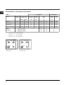
1
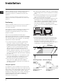
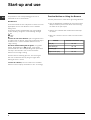
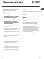
Operating Instructions HOB Contents GB English, 1 Installation, 2-6 Positioning Electrical connections Gas Connection Technical data Characteristic of the burners and nozzles Description of the appliance, 7 Overall view Start-up and use, 8 Practical Advise on Using the Burners Precautions and tips, 9 General safety Disposal PI 640 A GB PI 640 TC GB Maintenance and care, 10 Switching the appliance off Cleaning the appliance Greasing the Taps Troubleshooting, 11 GB Installation The hob should not be installed in a bed sitting room with a volume of less than 20m3. If it is installed in a room of volume less than 5m3 an air vent of effective area of 110cm2 is required, if it is installed in a room of volume between 5m3 and 10m3 an air vent of effective airvent of 50cm2 is required, while if the volume exceeds 11m3 no airvent is required. However, if the room has a door or a window which opens directly to the outside no air vent is required even with the volume is between 5m3 and 11m3. Intensive or prolonged use of the appliance could mean that extra aeration is needed, such as the opening of a window or a more powerful fan. If there are other fuel burning appliances in the same room, B.S. 5440 Part 2 Current Edition, should be consulted to determine the requisite air vent requirements. Min. 600 mm. min. 50 min. 50 The dimensions of the room for the furniture must be those indicated in the figures. Fixing hooks are provided which allow to place the hob plate on work tops that measure from 20 to 40 mm in thickness. To obtain a good fixing of the hob plate it is advisable to use all the hooks supplied. 555 mm m 55 m mm ! This unit may be installed and used only in permanently ventilated rooms according to the British Stancards Codes Of Practice: B.S. 6172 / B.S. 5440, Par. 2 and B.S. 6891 Current Editions. The following requirements must be observed: HOOD HOOD 475 ! The appliance must be installed by a qualified person according to the instructions provided. Incorrect installation may damage property or cause harm to people or animals. LESS THAN 420 min. 650 with hood min. 700 without hood ! Keep packaging material out of the reach of children. It can become a choking or suffocation hazard (see Precautions and tips). LESS THAN 420 Positioning Min. 420 mm. ! Please keep these operating instructions for future reference. Pass them on to possible new owners of the appliance. The hob may be located in a kitchen, a kitonen/diner or bed sitting room, but not in a bathroom or shower room. The furniture standing next to the unit, that is higher than the working boards, must be placed at least 600 mm from the edge of the board. The minimum distance combustible material can be fitted above the hob in line with the edges of the hob is 420mm. If is fitted below 420mm a space of 50mm must be allowed from the edges of the hob. The minimum distance combustible material kitchen units can be fitted directly above the hob is 700mm. min. 650 mm. with hood min. 700 mm. without hood ! Before operating your new appliance please read this instruction booklet carefully. It contains important information for safe use, installation and care of the appliance. Min. 420 mm. Fastening Clamps - Assembly Diagram Fitting the appliance 2 Clamp Position for H=20mm top 30 The appliance can be installed next to furniture units which are no taller than the top of the cooker hob. The wall in direct contact with the back panel of the cooker must be made of non-flammable material. During operation the back panel of the cooker could reach a temperature of 50°C above room temperature. For proper installation of the cooker, the following precautions must be taken: 20 GB Clamp Position for H=30mm top Front Electrical Connection for Gas Cooktop Fit the supply cord with a standard plug for the demand rate indicated on the rating plate or connect it directly to the electrical mains. In the latter case, a single pole switch must be placed between the appliance and the mains, with a minimum opening between the contacts of 3 mm in compliance with current safety codes (the earthing wire must not be interrupted by the switch). The power supply cord must be positioned so that it does not reach a temperature in excess of 50°C above room temperature at any point. 40 Clamp Position for H=40mm top GB Back ! Use the clamps contained in the "accessory kit." In the event the cooktop is not installed above a built-in oven, a wood panel must be inserted as insulation. This panel must be placed at least 20 mm from the bottom of the cooktop itself. ! The installer must ensure that the correct electrical connection has been made and that it is compliant with safety regulations. Before making the actual connection, make sure that: The fuse and electrical system can withstand the load required by the appliance; Ventilation When installing the cooktop above a built-in oven, the oven should be placed on two wooden strips; in the case of a joining cabinet surface, remember to leave a space of at least 45 x 560 mm at the back (see picture). . m 60 m 5 45 m m. ! The hob can only be installed above built-in ovens provided with cooling ventilation. Electrical connection The cooktops fitted with a tripolar electrical supply cord are designed to be be used with alternating current according to the indications on the rating plate located under the cooktop. The earthing wire can be identified by its yellow-green colour. In the case of installation over a built-in electric oven, the electrical connections for the cooktop and oven should be independent, not only for safety purposes, but also to facilitate removal of one or both in the future. That the electrical supply system is equiped with an efficient earth hook-up according to the norms and regulations prescribed by law; That the plug or switch is easily accessible. ! The wires in the mains lead are coloured in accordance with the following code: Green & Yellow - Earth Blue - Neutral Brown - Live As the colours of the wires in the mains lead may not correspond with the coloured markings identifying the terminals in your plug, proceed as follows: Connect the Green & Yellow wire to the terminal marked E or or coloured Green or Green & Yellow. Connect the Brown wire to the terminal marked L or coloured Red. Connect the Blue wire to the terminal marked N or coloured Black. ! The cable must not be bent or compressed. ! The cable must be checked regularly and replaced by authorised technicians only (see Assistance). ! The manufacturer declines any liability should these safety measures not be observed. 3 GB Gas Connection Adapting the Cooktop for Different Types of Gas The cooktop should be connected to the gas supply by an authorized installer. During installation of this product it is essential to fit an approved gas tap to isolate the supply from the appliance for the convenience of any subsequent removal or servicing. Connection of the appliance to the gas mains or liquid gas tanks must be carried out according to the safety standards currently in force, and only after it is ascertained that it is suitable for the type of gas to be used. If not, follow the instructions indicated in the section entitled, Adapting the Cooktop for Different Types of Gas. If the cooktop is to be connected to tanks containing liquid gas, use pressure regulators that comply with current safety standards. ! To insure that the appliance operates safety, the gas is regulated correctly and your appliance lasts over time, make sure that gas pressure levels comply with the indications given in Table 1, Nozzle and Burner Specifications. To adapt the cooktop to a different type of gas than that for which it was designed, (see the sticker under the hob or on the packaging), the burner nozzles must be changed, as follows: Gas Connection to Non-flexible Pipe (copper or steel) Regulation of Air Supply to the Burner The burners do not need a primary air regulator. ! Connection to the gas source must be done in such a way as to not create any stress points at any part of the appliance. The appliance is fitted with an adjustable, "L" shaped connector and a gasket for the attachment to the gas supply. Should this connector have to be turned, the gasket must be replaced (supplied with the appliance). The gas feed connector to the appliance is a threaded, male 1/2" connector for round gas pipe. Minimum Regulation Gas Connection to Flexible Steel Pipe The gas feed connector to the appliance is a threaded, male 1/2" connector for round gas pipe. Only use pipes, tubes and gaskets that comply with current safety codes. The maximum length of the flexible pipes must not exceed 2000 mm. Once the connection has been made, ensure that the flexible metal tube does not touch any moving parts and is not crushed. Check the Seal ! Once the appliance has been installed, make sure all the connections are properly sealed, using a soapy water solution. Never use a flame. 4 1. Remove the pan supports and slide the burners out of the cooktop. 2. Unscrew the nozzles using a 7mm socket wrench and replace them with those for the new type of gas. (See table 1, Burner and Nozzle Specifications). 3. Reassemble the parts following the instructions in reverse order. 4. On completing the operation, replace the old rating label with the one showing the new type of gas; the sticker is available from our Service Centres. 1. Turn the gas valve to minimum. 2. Remove the knob and turn the regulator screw (positioned either on the side of the top or inside the shaft) clockwise until the flame becomes small but regular. 3. Make sure that, when the knob is turned rapidly high to low, the flame does not go out. 4. In the event of a malfunction on appliances with the security device (thermocouple) when the gas supply is set at minimum, increase the minimum supply levels using the regulator screw. ! In the case of liquid gas, the regulation screw must be fully screwed in (clockwise). ! Once the adjustment has been made, apply sealing wax, or a suitable substitute, to the old seals on the by-pass. ! If the gas pressure is different than that prescribed, a pressure regulator must be installed at the source, in compliance with national standards governing the use of piped gas regulators. DATA PLATE GB Gas section Class: II2H3+ Rated power kW (1): 8,05 (585 g/h - G30) (575 g/h - G31) Electrical section voltage: 220-240V ~ 50/60Hz This appliance conforms to the following European Economic Community directives: - 73/23/EEC of 19/02/73 (Low Voltage) and subsequent amendments; - 89/336/EEC of 03/05/89 (Electromagnetic Compatibility) and subsequent amendments; - 90/396/EEC of 29/06/90 (Gas) and subsequent modifications; - 93/68/EEC of 22/07/93 and subsequent amendments. - 2002/96/EC (1): The values in g/h refer to the capacities with liquid gas (Butane, Propane). 5 GB Characteristic of the burners and nozzles Table 1 Liquid Gas Burner Diameter (mm) Thermal power kW (p.c.s.*) By-Pass 1/100 Nozzle 1/100 Natural Gas Flow* g/h Nozzle 1/100 Nomin. Ridot. (mm) (mm) *** ** (mm) Flow* l/h Fast (R) 100 3,00 0,70 41 87 218 214 128 286 Semi Fast (S) 75 1,90 0,40 30 70 138 136 104 181 Auxiliary (A) 51 1,00 0,40 30 52 73 71 76 95 Triple Crown (TC) 130 3,25 1,30 57 91 236 232 133 309 28-30 20 35 37 25 45 Nominal (mbar) Minimum (mbar) Maximum (mbar) Supply Pressures ** ** *** At 15°C and 1013 mbar-dry gas Propane P.C.S. = 50.37 MJ/kg. Butane P.C.S. = 49.47 MJ/kg. Natural P.C.S. = 37.78 MJ/m3 S R PI 640 A GB 6 S A S TC PI 640 TC GB S A 20 17 25 Description of the appliance Overall view GB Support Grid for Cookware Gas Burners Control Knobs for Gas Burners Ignition Button for Gas Burners Ignitor for Gas Burners 7 Start-up and use GB The position of the corresponding gas burner is indicated on each control knob. Gas Burners The burners differ in size and power. Choose the most appropriate one for the diameter of the cookware being used. The burner can be regulated with the corresonding control knob by using one of the following settings: Off High Low To turn on one of the burners, place a lighted match or lighter near the burner, press the knob all the way in and turn in the counter-clockwise direction to the "High" setting. On those models fitted with an ignitor, the ignition button, identified by the symbol, must first be pressed and then the corresponding knob pushed all the way in and turned in the counter-clockwise direction to the "High" setting. ! If the burner accidently goes out, turn off the gas with the control knob and try to light it again after waiting at least 1 minute. To turn off a burner, turn the knob in the clockwise direction until it stops (it should be on the setting). 8 Practical Advise on Using the Burners For best performance, follow these general guidelines: Use the appropriate cookware for each burner (see table) in order to prevent the flame from reaching the sides of the pot or pan; Alwasy use cookware with a flat bottom and keep the lid on; When the contents come to a boil, turn the knob to "Low". Burner ø Cookware Diameter (cm) Fast (R) 24 - 26 Semi Fast (S) 16 - 20 Auxiliary (A) 10 - 14 Triple Crown (TC) 24 - 26 Precautions and tips ! This appliance has been designed and manufactured in compliance with international safety standards. The following warnings are provided for safety reasons and must be read carefully. General safety This manual is for a class 3 built-in cooktop. Gas appliances require regular air exchange to ensure trouble-free performance. When installing the cooker, follow the instructions provided in the paragraph on Positioning the appliance. These instructions are only valid for the countries the symbols for which appear on the manual and the serial plate. This appliance was designed for domestic use inside the home and is not intended for commercial or industrial use. The appliance must not be installed outdoors, even in covered areas. It is extremely dangerous to leave the appliance exposed to rain and storms. Do not touch the appliance with bare feet or with wet or damp hands and feet. The appliance must be used by adults only, to cook food according to the instructions in this manual. Do not use the hob as a worktop or chopping board. Always make sure pan handles are turned towards the centre of the hob in order to avoid accidental burns. GB Avoid closing the cover (if present) while the gas burners and electric plates are still warm. Do not use cookware with uneven or deformed bottoms. Disposal When disposing of packaging material: observe local legislation so that the packaging may be reused. The European Directive 2002/96/EC on Waste Electrical and Electronic Equipment (WEEE), requires that old household electrical appliances must not be disposed of in the normal unsorted municipal waste stream. Old appliances must be collected separately in order to optimise the recovery and recycling of the materials they contain and reduce the impact on human health and the environment. The crossed out wheeled bin symbol on the product reminds you of your obligation, that when you dispose of the appliance it must be separately collected. Consumers should contact their local authority or retailer for information concerning the correct disposal of their old appliance. Ensure that power supply cables of other electrical appliances do not come into contact with the hot parts of the hob. The openings and slots used for ventilation and heat dispersion must never be covered. Make sure the knobs are in the •/¡ position when the appliance is not in use. When unplugging the appliance always pull the plug from the mains socket, do not pull on the cable. Never carry out any cleaning or maintenance work without having unplugged the plug from the mains. 9 Maintenance and care GB Switching the appliance off Greasing the Taps Disconnect your appliance from the electricity supply before carrying out any work on it. The taps may jam in time or they may become difficult to turn. If so, the tap itself must be replaced. Cleaning the appliance ! This operation must be performed by a technician authorised by the manufacturer. ! Do not use abrasive or corrosive detergents, stain removers, anti-rust products, powder detergents or sponges with abrasive surfaces: these may scratch the surface. ! Never use steam cleaners or pressure cleaners on the appliance. It is usually enough to wash the hob with a damp sponge and dry it with absorbent kitchen roll. The flame spreaders should be washed frequently with hot water and detergent, taking care to eliminate any scale. In the hob equipped with automatic lighting, the terminal part of the electronic instant lighting devices should be cleaned frequently and the gas outlet holes on the flame spreaders should be checked to make sure they are free of any obstructions. Stainless steel may become marked if it comes into contact with very hard water or harsh detergents (containing phosphorous) for long periods of time. After cleaning, it is advisable to rinse thoroughly and dry. It is also recommended that drops of water be dried. 10 Troubleshooting It may happen that the appliance does not function properly or at all. Before calling the service centre for assistance, check if anything can be done. First, check to see that there are no interruptions in the gas and electrical supplies, and, in particular, that the gas valves for the mains are open. GB Problem Possible causes/Solution The burner does not light or the flame is not even around the burner. The gas holes on the burner are clogged. All the movable parts that make up the burner are mounted correctly. There are draughts near the appliance. The flame dies in models with a safety device. You pressed the knob all the way in. You keep the knob pressed in long enough to activate the safety device. The gas holes are not blocked in the area corresponding to the safety device. The burner does not remain lit when set to minimum. The gas holes are not blocked. There are no draughts near the appliance. The minimum setting has been adjusted properly. The cookware is unstable. The bottom of the cookware is perfectly flat. The cookware is positioned correctly at the centre of the burner. The pan support grids have been positioned correctly. If, despite all these checks, the hob does not function properly and the problem persists, call the nearest Customer Service Centre. Please have the following information handy: The appliance model (Mod.). The serial number (S/N). This information can be found on the data plate located on the appliance and/or on the packaging. ! Never use unauthorised technicians and never accept replacement parts which are not original. 11 04/2005 - 195045883.01 XEROX BUSINESS SERVICES GB 12