1
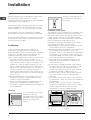
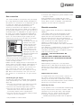
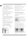
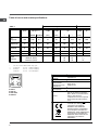
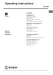
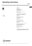
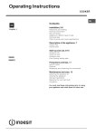
Operating Instructions COOKER GB GB English, 1 Contents Installation, 2-6 Positioning and levelling Electrical connections Gas connection Adapting to different types of gas Technical data Table of burner and nozzle specifications Description of the appliance, 7 Overall view Control panel Start-up and use, 8-10 K3G2/G K3G21/G K3G21S/IR K3G2S/G Using the hob Using the oven Analogue timer Oven cooking advice table Precautions and tips, 11 General safety Disposal Respecting and conserving the environment Maintenance and care, 12 Switching the appliance off Cleaning the appliance Gas tap maintenance Replacing the oven light bulb Assistance Installation The legs* fit into the slots on the underside of the base of the cooker. Before operating your new appliance please read this instruction booklet carefully. It contains important information concerning the safe installation and operation of the appliance. Please keep these operating instructions for future reference. Make sure that the instructions are kept with the appliance if it is sold, given away or moved. The appliance must be installed by a qualified professional according to the instructions provided. Any necessary adjustment or maintenance must be performed after the cooker has been disconnected from the electricity supply. Positioning ! This unit may be installed and used only in permanently ventilated rooms according to the British Standards Codes Of Practice: B.S. 6172/B.S. 5440, Par. 2 and B.S. 6891 Current Editions. The following requirements must be observed: a ) The cooker should not be installed in a bed sitting room with a volume of less than 20m3. If it is installed in a room of volume less than 5m3 an air vent of effective area of 110cm2 is required, if it is installed in a room of volume between 5m3 and 10m3 a supplementary airvent area of 50cm2 is required, if the volume exceeds 11m3 no airvent is required. However, if the room has a door or a window which opens directly to the outside no air vent is required even when the volume is between 5m3 and 11m3. b )During prolonged use of the appliance you may consider it necessary to open a window to the outside to improve ventilation. c ) If there are other fuel burning appliances in the same room, B.S.5440 Part 2 Current Edition, should, be consulted to determine the requisite air vent requirements. Installation of the cooker The appliance can be installed next to furniture units which are no taller than the top of the cooker hob. The wall in direct contact with the back panel of the cooker must be made of non-flammable material. During operation the back panel of the cooker could reach a temperature of 50°C above room temperature. For proper installation of the cooker, the following precautions must be taken: a ) The appliance can be placed in a kitchen, dining room or bedsit, but not in a bathroom. b )All furniture around the appliance must be placed at least 200 mm from the top of the cooker, should the surface of the appliance be higher than the worktop of this furniture. Curtains should not be placed behind the cooker or less than 200 mm away from the sides of the appliance. c ) Any hoods must be installed according to the requirements in the installation manual for the hoods themselves. d )If the cooker is installed beneath a wall cabinet, the latter must be situated at a minimum of 420 mm above the hob. The minimum distance between the worktop and kitchen units made of combustible material is 700 mm (Fig. A). e ) The wall in direct contact with the back panel of the cooker must be made of non-flammable materials. f ) The cooker is fitted with a safety chain that must be attached to a hook, secured to the wall behind the appliance. Some models can have their gas connection inverted. It is important to make sure the safety chain is always situated on the side which corresponds to the hose holder (Fig. B). Levelling 420 mm. Fig. A 2 600 mm. Min. Min. min. 650 mm. with hood min. 700 mm. without hood HOOD 420 mm. If it is necessary to level the appliance, screw the adjustable feet into the places provided on each corner of the base of the cooker (see figure). Min. GB Fig. B Gas connection 700 mm T he cooker should be connected to the gas-supply by a corgi registered installer. During installation of this product it is essential to fit an approved gas tap to isolate the supply from the appliance for the convenience of any subsequent removal or servicing. Connection of the appliance to the gas mains or liquid gas must be carried out according to the prescribed regulation in force, and only after it is ascertained that it is adaptable to the type of gas to be used. If not, follow the instructions indicated in the paragraph headed Adaptation to different gas types. On some models the gas supply can be connected on the left or on the right, as necessary; to change the connection, reverse the position of the hose HOT PARTS holder with that of the cap and replace the gasket (supplied with the appliance). In the case of connection to liquid gas, by tank, use pressure regulators that conform to the regulation in force. The gas supply must be connected to the left of the appliance. Be sure that the hose does not pass through the rear of the cooker touching hot parts. Make sure the supply pressure conforms with the values shown in the table entitled Caracteristics of the burners and nozzles. When the cooker is installed between cabinets (recessed), the gas connection must be effected by an approved flexible hose with bayonet fitting (BS 669 Current Edition). The gas inlet for the cookers is a threaded G 1/2 gas female fitting. Connecting the gas supply To make the connection, a flexible hose should be used corresponding to the current gas regulations which are: the hose must never be at any point in its lenght in contact with the hot parts of the cooker; the hose must never be longer than 1,5 metre; the hose must not be subject to any tension or torsional stress and it must not have any excessively narrow curves or bottlenecks; the hose must be easy to inspect along its entire length to check its condition; * Only available in certain models the hose must always be in good condition, never attempt to repair. The installation must comply with gas safety (installation and use) regulations 1984. In all cases for the above, by low, a qualified, corgi approved engineer must be called for installation. Electrial connection Power supply voltage and frequency: 230-240V a.c. 50/60 Hz. ! The supply cable must be positioned so that it never reaches at any point a temperature 50°C higher than the room temperature. The cable must be routed away from the rear vents. Should you require it, you may use a longer cable, however, you must ensure that the cable supplied with the appliance is replaced by one of the same specifications in accordance with current standards and legislation. Your appliance is supplied with a 13 amp fused plug that can be plugged into a 13 amp socket for immediate use. Before using the appliance please read the instructions below. WARNING - THIS APPLIANCE MUST BE EARTHED. THE FOLLOWING OPERATIONS SHOULD BE CARRIED OUT BY A QUALIFIED ELECTRICIAN. Replacing the fuse: When replacing a faulty fuse, a 13 amp ASTA approved fuse to BS 1362 should always be used, and the fuse cover re-fitted. If the fuse cover is lost, the plug must not be used until a replacement is obtained. Replacement fuse covers: If a replacement fuse cover is fitted, it must be of the correct colour as indicated by the coloured marking or the colour that is embossed in words on the base of the plug. Replacements can be obtained directly from your nearest Service Depot. Removing the plug: If your appliance has a non-rewireable moulded plug and you should wish to remove it to add a cable extension or to re-route the mains cable through partitions, units etc., please ensure that either: the plug is replaced by a fused 13 amp rewireable plug bearing the BSI mark of approval. or: 3 GB GB the mains cable is wired directly into a 13 amp cable outlet, controlled by a switch, (in compliance with BS 5733) which is accessible without moving the appliance. ! For appliances with a rating greater than 13 amp (eg: electric hob, double ovens and freestanding electric cookers etc.) the mains cable must be wired into a cooker output point with a rating of 45 amp. In this case the cable is not supplied. Disposing of the plug: Ensure that before disposing of the plug itself, you make the pins unusable so that it cannot be accidentally inserted into a socket. Instructions for connecting cable to an alternative plug: ! The wires in the mains lead are coloured in accordance with the following code: Green & Yellow - Earth Blue - Neutral Brown - Live If the colours of the wires in the mains lead do not correspond with the coloured markings identifying the terminals in your plug, proceed as follows: Connect Green & Yellow wire to terminal marked E or or coloured Green or Green & Yellow. Connect Brown wire to terminal marked L or coloured Red. Connect Blue wire to terminal marked N or coloured Black. If a 13 amp plug (BS 1363) is used it must be fitted with a 13 amp fuse. A 15 amp plug must be protected by a 15 amp fuse, either in the plug or adaptor or at the distribution board. If you are in any doubt about the electrical supply to your machine, consult a qualified electrician before use. How to connect an alternative plug: The wires in this mains lead are coloured in accordance with the following code: BLUE NEUTRAL (N) BROWN LIVE (L) GREEN AND YELLOW EARTH (E) Disposing of the appliance When disposing of the appliance please remove the plug by cutting the mains cable as close as possible to the plug body and dispose of it as described above. Checking the connection for leaks When the installation process is complete, check the hose fittings for leaks using a soapy solution. Never use a flame. Adapting to different types of gas It is possible to adapt the appliance to a type of gas other than the default type (this is indicated on the rating label on the cover). Adapting the hob Replacing the nozzles for the hob burners: 1. Remove the hob grids and slide the burners off their seats. 2. Unscrew the nozzles using a 7 mm socket spanner (see figure), and replace them with nozzles suited to the new type of gas (see Burner and nozzle specifications table). 3. Replace all the components by following the above instructions in reverse. Adjusting the hob burners minimum setting: 1. Turn the tap to the minimum position. 2. Remove the knob and adjust the regulatory screw, which is positioned inside or next to the tap pin, until the flame is small but steady. If the appliance is connected to a liquid gas supply, the regulatory screw must be fastened as tightly as possible. GREEN & YELLOW BROWN BLUE 13 amp fuse CROSS-BAR CORD GRIP 3. While the burner is alight, quickly change the position of the knob from minimum to maximum and vice versa several times, checking that the flame is not extinguished. 4 The hob burners do not require primary air adjustment. After adjusting the appliance so it may be used with a different type of gas, replace the old rating label with a new one that corresponds to the new type of gas (these labels are available from Authorised Technical Assistance Centres). Should the gas pressure used be different (or vary slightly) from the recommended pressure, a suitable pressure regulator must be fitted to the inlet hose in accordance with current national regulations relating to regulators for channelled gas. 5. Turn the knob from the MAX position to the MIN position quickly or open and shut the oven door, making sure that the burner is not extinguished. GB Adapting the grill Replacing the grill burner nozzle: 1. Remove the oven burner after loosening screw V (see figure). V Adapting the oven Replacing the oven burner nozzle: 1. Remove the oven compartment. 2. Slide out the protection panel A (see diagram). A V 3. Remove the oven burner after unscrewing the screws V (see figure). The whole operation will be made easier if the oven door is removed. 4. Unscrew the nozzle using a special nozzle socket spanner (see figure) or with a 7 mm socket spanner, and replace it with a new nozzle that is suited to the new type of gas (see Burner and nozzle specifications table). 2. Unscrew the grill burner nozzle using a special nozzle socket spanner (see figure) or preferably with a 7 mm socket spanner, and replace it with a new nozzle that is suited to the new type of gas (see Burner I and nozzle specifications table). Be careful of the spark plug wires and the thermocouple tubes. The oven and grill burners do not require primary air adjustment. After adjusting the appliance so it may be used with a different type of gas, replace the old rating label with a new one that corresponds to the new type of gas (these labels are available from Authorised Technical Assistance Centres). Should the gas pressure used be different (or vary slightly) from the recommended pressure, a suitable pressure regulator must be fitted to the inlet hose in accordance with current national regulations relating to regulators for channelled gas. Adjusting the gas oven burners minimum setting: 1. Light the burner (see Start-up and Use). 2. Turn the knob to the minimum position (MIN) after it has been in the maximum position (MAX) for approximately 10 minutes. 3. Remove the knob. 4. Tighten or loosen the adjustment screws on the outside of the thermostat pin (see figure) until the flame is small but steady. If the appliance is connected to liquid gas, the adjustment screw must be fastened as tightly as possible. 5 GB Table of burner and nozzle specifications Table 1 Liquid Gas Burner Diameter (mm) Thermal Power kW (p.c.s.*) By-Pass 1/100 Nozzle 1/100 Natural Gas Flow* g/h Nozzle 1/100 Nominal Reduced (mm) (mm) *** ** (mm) Flow* l/h Fast (Large)(R) 100 3.00 0.7 41 87 218 214 128 286 Semi Fast (Medium)(S) 75 1.90 0.4 30 70 138 136 104 181 Auxiliary (Small)(A) 51 1.00 0.4 30 52 73 71 76 95 Oven - 3.10 1.0 46 85 225 221 132 295 Grill - 2.50 - - 80 182 179 122 227 28-30 20 35 37 25 45 Nominal (mbar) Minimum (mbar) Maximum (mbar) Supply Pressures * ** *** At 15°C and 1013 mbar- dry gas Propane P.C.S. = 50,37 MJ/Kg Butane P.C.S. = 49,47 MJ/Kg Natural P.C.S. = 37,78 MJ/m3 S S A R K3G2/G K3G21/G K3G21S/IR K3G2S/G 6 20 17 25 TECHNICAL DATA Oven dimensions (HxWxD) Volume Useful measurements relating to the oven compartment Power supply voltage and frequency Burners 34x39x44 cm 58 l width 42 cm depth 44 cm height 23 cm see data plate may be adapted for use with any type of gas shown on the data plate, which is located inside the flap or, after the oven compartment has been opened, on the left-hand wall inside the oven. EC Directives: 2006/95/EC dated 12/12/06 (Low Voltage) and subsequent amendments 04/108/EC dated 03/05/89 (Electromagnetic Compatibility) and subsequent amendments 90/369/EEC dated 29/06/90 (Gas) and subsequent amendments 93/68/EEC dated 22/07/93 and subsequent amendments 2002/96/EC. Descriptionof the appliance Overall view GB Gas burner Hob grid Containment surface for spills GUIDE RAILS for the sliding racks position 5 position 4 position 3 position 2 position 1 Control panel GRILL DRIPPING PAN Adjustable foot Adjustable foot Control panel TIMER knob* OVEN control knob GAS BURNER ignition button* Hob BURNER control knobs OVEN LIGHT and ROTISSERIE button* * Only available in certain models. 7 Start-up and use GB Using the hob Lighting the burners For each BURNER knob there is a complete ring showing the strength of the flame for the relevant burner. To light one of the burners on the hob: 1. Bring a flame or gas lighter close to the burner. 2. Press the BURNER knob and turn it in an anticlockwise direction so that it is pointing to the maximum flame setting -. 3. Adjust the intensity of the flame to the desired level by turning the BURNER knob in an anticlockwise direction. This may be the minimum setting +, the maximum setting - or any position in between the two. If the appliance is fitted with an electronic lighting device* (see figure), press the ignition button, marked with the symbol , then hold the BURNER knob down and turn it in an anticlockwise direction, towards the maximum flame setting, until the burner is lit. Several models are equipped with an ignition device which is built into the knob; in this case the electronic ignition device* is present (see figure) but the ignition button is not. Simply press the BURNER knob and turn it in an anticlockwise direction so that it is pointing to the maximum flame setting, until the burner is lit. The burner may be extinguished when the knob is released. If this occurs, repeat the operation, holding the knob down for a longer period of time. If the flame is accidentally extinguished, switch off the burner and wait for at least 1 minute before attempting to relight it. If the appliance is equipped with a flame failure safety device*, press and hold the BURNER knob for approximately 2-3 seconds to keep the flame alight and to activate the device. To switch the burner off, turn the knob until it reaches the stop position . HOB GAS BURNER SAFETY DEVICE ELECTRONIC LIGHTING DEVICE * Only available in certain models. 8 Practical advice on using the burners For the burners to work in the most efficient way possible and to save on the amount of gas consumed, it is recommended that only pans that have a lid and a flat base are used. They should also be suited to the size of the burner. Burner ø Cookware diameter (cm) Fast (R) 24 - 26 Semi Fast (S) 16 - 20 Auxiliary (A) 10 - 14 To identify the type of burner, please refer to the diagrams contained in the Burner and nozzle specifications. Using the oven The first time you use your appliance, heat the empty oven with its door closed at its maximum temperature for at least half an hour. Ensure that the room is well ventilated before switching the oven off and opening the oven door. The appliance may emit a slightly unpleasant odour caused by protective substances used during the manufacturing process burning away. Before operating the product, remove all plastic film from the sides of the appliance. Never put objects directly on the bottom of the oven; this will avoid the enamel coating being damaged. Only use position 1 in the oven when cooking with the rotisserie spit. Lighting the oven To light the oven burner, bring a flame or gas lighter close to opening F (see figure) and press the OVEN control knob while turning it in an anticlockwise direction until it reaches the MAX position. If, after 15 seconds, the burner is still not alight, release the knob, open the oven door and wait for at least 1 minute before trying to light it again. F The oven is fitted with a safety device and it is therefore necessary to hold the OVEN control knob down for approximately 6 seconds. If the flame is accidentally extinguished, switch off the burner and wait for at least 1 minute before attempting to relight the oven. Adjusting the temperature dishes. To open the door pull it downwards (see figure). To set the desired cooking temperature, turn the OVEN control knob in an anticlockwise direction. Temperatures are displayed on the control panel and may vary between MIN (140°C) and MAX (250°C). Once the set temperature has been reached, the oven will keep it constant by using its thermostat. Grill To light the grill, bring a flame or gas lighter close to the burner and press the OVEN control knob while turning it in a clockwise direction until it reaches the , position. The grill enables the surface of food to be browned evenly and is particularly suitable for roast dishes, schnitzel and sausages. Place the rack in position 4 or 5 and the dripping pan in position 1 to collect fat and prevent the formation of smoke. The grill is fitted with a safety device and it is therefore necessary to hold the OVEN control knob down for approximately 6 seconds. The internal surfaces of the compartment (where present) may become hot. Do not place flammable materials in the lower oven compartment. In gas cooker models, there is a sliding protection layer A that shields the lower compartment from the heat generated by the burner (see figure). To remove the sliding protection remove the screw S (see figure). To replace it, lock it in place with the screw S. A If the flame is accidentally extinguished, switch off the burner and wait for at least 1 minute before attempting to relight the grill. When using the grill, leave the oven door ajar, positioning the deflector D between the door and the control panel (see figure) in order to prevent the knobs from overheating. D GB Before using the oven make sure that the sliding protection is fixed correctly. S Oven light The light may be switched on at any moment by pressing the OVEN LIGHT button. Timer* To activate the Timer proceed as follows: 1. Turn the TIMER knob in a clockwise direction " for almost one complete revolution to set the buzzer. 2. Turn the TIMER knob in an anticlockwise direction # to set the desired length of time. Lower compartment* There is a compartment underneath the oven that may be used to store oven accessories or deep * Only available in certain models. 9 GB Oven cooking advice table Foods Pasta Lasagne Cannelloni Gratin dishes Meat Veal Chicken Duck Rabbit Pork Lamb Fish Mackerel Dentex Trout baked in foil Pizza Neapolitan-style Pies Biscuits Tart Savoury pies Leavened cakes Grilled foods Veal steak Cutlets Hamburgers Mackerel Toast * Only available in certain models. 10 Weight (in kg) Rack position Preheating time (min) Recommended Temperature (°C) Cooking time (minutes) 2.5 2.5 2.5 3 3 3 10 10 10 210 200 200 60-75 40-50 40-50 1.7 1.5 1.8 2 2.1 1.8 3 3 3 3 3 3 10 10 10 10 10 10 200 220 200 200 200 200 85-90 90-100 100-110 70-80 70-80 90-95 1.1 1.5 1 3 3 3 10 10 10 180-200 180-200 180-200 35-40 40-50 40-45 1 3 15 220 15-20 0.5 1.1 1 1 3 3 3 3 15 15 15 15 180 180 180 180 30-35 30-35 45-50 35-40 1 1.5 1 1 4 pcs 4 4 3 4 4 5 5 5 5 5 15-20 20 7 15-20 5 Precautions and tips This appliance has been designed and manufactured in compliance with international safety standards. The following warnings are provided for safety reasons and must be read carefully. General safety These instructions are only valid for the countries whose symbols appear in the manual and on the serial number plate. The appliance was designed for domestic use inside the home and is not intended for commercial or industrial use. The appliance must not be installed outdoors, even in covered areas. It is extremely dangerous to leave the appliance exposed to rain and storms. Do not touch the appliance with bare feet or with wet or damp hands and feet. The appliance must be used by adults only for the preparation of food, in accordance with the instructions provided in this booklet (the instructions apply to all countries listed at the beginning of the booklet). The instruction booklet accompanies a class 1 (insulated) or class 2 - subclass 1 (recessed between 2 cupboards) appliance. Keep children away from the oven. Make sure that the power supply cables of other electrical appliances do not come into contact with the hot parts of the oven. The openings used for the ventilation and dispersion of heat must never be covered. Always use oven gloves when placing cookware in the oven or when removing it. Do not use flammable liquids (alcohol, petrol, etc...) near the appliance while it is in use. Do not place flammable material in the lower storage compartment or in the oven itself. If the appliance is switched on accidentally, it could catch fire. Always make sure the knobs are in the position and that the gas tap is closed when the appliance is not in use. When unplugging the appliance, always pull the plug from the mains socket; do not pull on the cable. Never perform any cleaning or maintenance work without having disconnected the appliance from the electricity mains. Repairs carried out by inexperienced persons may cause injury or further malfunctioning of the appliance. Contact Assistance. Do not rest heavy objects on the open oven door. The appliance should not be operated by people (including children) with reduced physical, sensory or mental capacities, by inexperienced individuals or by anyone who is not familiar with the product. These individuals should, at the very least, be supervised by someone who assumes responsibility for their safety or receive preliminary instructions relating to the operation of the appliance. Do not let children play with the appliance. Disposal When disposing of packaging material: observe local legislation so that the packaging may be reused. The European Directive 2002/96/EC relating to Waste Electrical and Electronic Equipment (WEEE) states that household appliances should not be disposed of using the normal solid urban waste cycle. Exhausted appliances should be collected separately in order to optimise the cost of re-using and recycling the materials inside the machine, while preventing potential damage to the atmosphere and to public health. The crossed-out dustbin is marked on all products to remind the owner of their obligations regarding separated waste collection. Exhausted appliances may be collected by the public waste collection service, taken to suitable collection areas in the area or, if permitted by current national legislation, they may be returned to the dealers as part of an exchange deal for a new equivalent product. All major manufacturers of household appliances participate in the creation and organisation of systems for the collection and disposal of old and disused appliances. Respecting and conserving the environment You can help to reduce the peak load of the electricity supply network companies by using the oven in the hours between late afternoon and the early hours of the morning. Check the door seals regularly and wipe them clean to ensure they are free of debris so that they adhere properly to the door, thus avoiding heat dispersion. If the appliance breaks down, under no circumstances should you attempt to repair the appliance yourself. 11 GB Care and maintenance 02/2009 - 195049686.03 XEROX FABRIANO GB Switching the appliance off Inspecting the oven seals Disconnect your appliance from the electricity supply before carrying out any work on it. Check the door seals around the oven periodically. If the seals are damaged, please contact your nearest Authorised After-sales Service Centre. We recommend that the oven is not used until the seals have been replaced. Cleaning the appliance Do not use abrasive or corrosive detergents such as stain removers, anti-rust products, powder detergents or sponges with abrasive surfaces: these may scratch the surface beyond repair. Never use steam cleaners or pressure cleaners on the appliance. It is usually sufficient simply to wash the hob using a damp sponge and dry it with absorbent kitchen roll. The stainless steel or enamel-coated external parts and the rubber seals may be cleaned using a sponge that has been soaked in lukewarm water and neutral soap. Use specialised products for the removal of stubborn stains. After cleaning, rinse well and dry thoroughly. Do not use abrasive powders or corrosive substances. The hob grids, burner caps, flame spreader rings and the hob burners can be removed to make cleaning easier; wash them in hot water and non-abrasive detergent, making sure all burnt-on residue is removed before drying them thoroughly. For hobs with electronic ignition, the terminal part of the electronic lighting devices should be cleaned frequently and the gas outlet holes should be checked for blockages. The inside of the oven should ideally be cleaned after each use, while it is still lukewarm. Use hot water and detergent, then rinse well and dry with a soft cloth. Do not use abrasive products. Clean the glass part of the oven door using a sponge and a non-abrasive cleaning product, then dry thoroughly with a soft cloth. Do not use rough abrasive material or sharp metal scrapers as these could scratch the surface and cause the glass to crack. The accessories can be washed like everyday crockery, and are even dishwasher safe. Stainless steel can be marked by hard water that has been left on the surface for a long time, or by aggressive detergents containing phosphorus. After cleaning, rinse well and dry thoroughly. Any remaining drops of water should also be dried. 12 Gas tap maintenance Over time, the taps may become jammed or difficult to turn. If this occurs, the tap must be replaced. This procedure must be performed by a qualified technician who has been authorised by the manufacturer. Replacing the oven light bulb 1. After disconnecting the oven from the electricity mains, remove the glass lid covering the lamp socket (see figure). 2. Remove the light bulb and replace it with a similar one: voltage 230 V, wattage 25 W, cap E 14. 3. Replace the lid and reconnect the oven to the electricity supply. Assistance Please have the following information handy: The appliance model (Mod.). The serial number (S/N). This information can be found on the data plate located on the appliance and/or on the packaging.