1
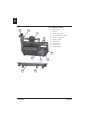
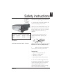
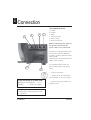
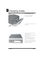
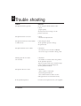
ENG
Operators guide
MP Compact4
4
1
3
2
5
6
7
Overview
1.
2.
3.
4.
Front cover
Top cover
Media roll
Roll guide
5.
6.
7.
8.
9.
Status lamp
Print button
Print roller
Release lever
Paper path
10.
11.
12.
13.
Spindle
Communication ports
Power connection
Power switch
9
8
11
10
4
9
12
A26618-A
13
ENGLISH - 1
ENG
MP Compact4 Mobile
14.
15.
16.
17.
18.
19.
20.
21.
22.
23.
14
16
15
17
Roll guide
Spool
Locking handle
Communication ports
Power connection
Power switch
Lock plate
Lock guide
Lock clips
Bottom plate
19
20
21
23
2 - ENGLISH
18
22
A26618-A
This symbol is used to notify the reader
of situations requiring special attention.
• Ensure that the power switch is off
when connecting to the socket.
The user is only authorized to carry out
tasks which are covered by this manual.
For any other tasks users are to refer to
a qualified service technician or
supplier.
• Ensure that the power cable is
Height: 105 mm disconnected before opening the
printer.
Weight: 3.5 kg
Dimensions & Weight for base model
Width: 230 mm
Depth: 260 mm
CAUTION
DOUBLE POLE/NEUTRAL FUSING
When cleaning or changing the print
head do not use any sharp objects.
Don't use any sharp objects to
remove labels from the print roller.
•
Required tools
- A pen or other pointed tool
- Pozidrive 1 screwdriver
- Allen keys 1-5 mm
- Flat head screwdriver max 2.5 mm
• Do not use cables longer than 5 m
for serial data communication. This may
result in data being lost or corrupted.
This is especially important in
environments which are prone to high
levels of electronic interference.
A26618-A
ENGLISH - 3
ENG
Safety instructions
ENG
Connection
To a computer or server
3
4
1
2
1. COM1
2. COM2
3. USB
4. Ethernet/LAN
5. Power switch
6. Power connection
Before connecting any cables to
the printer ensure that the
power cable is not connected.
The printer is equipped with serial
connections: 300-115 000 baud
(COM 1, COM 2). Ethernet TCP/
IP and USB.
USB will only work with Windows
2000 or later versions.
6
5
Use shielded cables and do not
place them parallel to the power
cable.
- Connect the cables.
• Always ensure that the cables
are connected to the correct port!
Power consumption of the base model
Maximum consumption: 0.7 A
Standby
45 mA (10-12W)
- Connect the power cable to an
earthed socket.
The printer shall be connected to an
earthed socket when the power cable
is connected.
4 - ENGLISH
A26618-A
Base model
The printer stops automatically
when it is out of media.
This is indicated by an LED, the
status lamp will indicate red.
- Turn the release lever to lift the
printhead.
- Remove the roll guide and the
empty media spool if applicable.
- Insert a new roll of media, as far
to the left as possible.
- Insert the media roll from the
side.
- Position and lock the roll guide.
- Turn the release lever to PRINT.
- Close the front cover.
- Feed through a blank label.
- Press the start button in order to
find the correct media position.
The printer will automatically read
the position of the media so that
printing starts correctly.
A26618-A
ENGLISH - 5
ENG
Changing media
ENG
Changing media
Printer equipped with cutter
- Pull out the locking pin.
- Fold down the cutter.
• Follow the instructions for the
base model.
- Feed the end of the media roll
through the cutter.
- Pull out the locking pin and fold
back the cutter.
- Feed through a blank label.
- Press the start button in order to
find the correct media position.
The printer will automatically read
the position of the media so that
printing starts correctly.
6 - ENGLISH
A26618-A
Printer with Peel-Off kit
Follow the instructions for the base
model.
- Remove several labels from the
carrier paper.
Feed the media
- behind the lower part of the front
cover
- through the reeling pins
- Pull the reeling device counterclockwise in order to increase
tension of the carrier paper.
- Press the start button in order to
find the correct media position.
MP Compact4 Mobile
The roller guide is blocked by a
locking device, which enables the
printer to be used in a vertical
position in a mobile environment.
- Turn the release lever to lift the
printhead.
- Remove the roll guide.
- Insert a new media roll.
- Feed in from the side of the
printer.
- Insert roll and lock the roll guide.
- Turn the release lever to PRINT.
- Feed through a blank label.
- Press the start button in order to
find the correct media position.
The printer will automatically read
the position of the media so that
printing starts correctly.
A26618-A
ENGLISH - 7
ENG
Changing media
ENG
Cleaning
Base model
- Turn the release lever to lift the
printhead.
- Remove the media roll.
• Use the special cleaning cloths
provided.
- Feed in the cloth in the same
manner as the media.
- Turn the release lever to PRINT.
- Hold on to the cloth.
- Start the printer by pressing the
red print button.
- Keep holding on to the cloth for
several seconds (the roller is cleaned).
- Let go of the cloth (the print
head is cleaned).
Discard the cleaning cloth.
Printer with cutter
- Pull out the locking pin.
- Fold down the cutter.
• Follow instructions for the base
model.
8 - ENGLISH
A26618-A
Base model
- Open the front cover.
- Lift up the top cover by pressing
carefully with a pen or similar on
the catch.
- Loosen the locking plug.
- Press on the roller with your
thumb and move it to the left.
- Lift out the right hand part of
the roller.
- Move the roller along the opening.
- Lift out the roller.
Replace roller in a reverse order.
• Ensure that the pinion engages
the driving belt. The driving belt
stretches when the roller is in the
correct position.
A26618-A
ENGLISH - 9
ENG
Changing the roller
ENG
Changing the print head
Warning!
Before beginning any work on
the printer ensure that the
power cable is not connected.
- Open the printer.
- Turn the release lever to PRINT.
- Remove the retaining screw.
- Press carefully on the front part
of the head so that the two screw
heads become free.
- Carefully loosen the connector at
the rear.
• Handle the print head with
care.
For information on the printer’s status:
Conduct a test print
- Load the media.
Use an approximately 110 mm wide print width.
- Hold in the start button.
- Turn on the power switch.
A test print will occur.
10 - ENGLISH
- Mount the new print head.
- Insert the connector at the rear.
- Replace the retaining screw.
- Turn the release lever to lift the
printhead.
- Close the printer.
- Feed in the media.
- Turn the release lever to PRINT.
• Ensure that the printed pattern
is even across the entire width of
the print surface. Any secondary
adjustment should be made according to instructions in the “Print
head adjustment” section.
- Exit test mode by shutting off the
power switch.
A26618-A
Adjusting the print head pressure
Adjusting the pressure of the
print head is necessary when
using different types of media,
e.g. labels, paper or tickets.
- Open the front cover.
- Turn the release lever to lift the
printhead.
Use a small flathead screwdriver and
turn the adjusting screws counterclockwise in order to increase the
pressure (about 0,5 - 1 turns).
For information on the printer’s
status:
Conduct a test print
- Load the media.
Use an approximately 110 mm
wide print width.
- Hold in the start button.
- Turn on the power switch.
A test print will occur
• Ensure that the printed pattern
is even across the entire width of
the print surface. Any secondary
adjustment should be made according to instructions in the “Print
head adjustment” section.
- Exit test mode by shutting off the
power switch.
A26618-A
ENGLISH - 11
ENG
Print head adjustment
ENG
Accessories
150 mm kit
This accessory makes it possible to
use a 150 mm media roll instead of a
standard 100 mm roll.
Mounting
- Unscrew the existing spindle.
- Install your 150 mm kit.
- Screw on the new spindle.
Peel-Off kit
The Peel-Off accessory separates
lables from their carrier paper.
The carrier paper is rolled up under
the printer.
This will only work with 100 mm
rolls.
• This accessory may only be
installed at the factory or by a
qualified service technician.
12 - ENGLISH
A26618-A
LTS kit
Label Taken Sensor, is most often
used together with the Peel-Off kit.
The photo cell controls the print out
so that a new label is printed only
after the previous label has been
removed.
For installation contact a qualified
service technician or your supplier.
Wall mounting
Enables wall mounting of the
printer.
- Secure the mounting plate on the
underside of the printer.
- Screw the guide securely to the wall
plate.
- Mount the wall plate.
- Hang up the printer.
A26618-A
ENGLISH - 13
ENG
Accessories
ENG
Accessories
Print Head Diagnostic (PHD)
Printers with an article number of
645130.02 or later can be equipped
with PHD-Print Head Diagnostic.
PHD warns against missing dots on
the print head. PHD requires
Labelpoint 4.49 or later versions.
• This accessory may only be
installed at the factory or by a qualified service technician.
Tower Mounting kit
Two MP Compact4 printers can be
stacked on top of eachother. This is a
great solution in areas with a lack of
space and in situations where printing
of different types of media is required.
• For installation contact your
supplier or a qualified service technician.
14 - ENGLISH
A26618-A
Parallel cable
The parallel cable converts data from
parallel to serial communication. The
MP Compact4 is not equipped with a
parallelport, but with the help of the
cable, information can be sent via the
computer’s parallel port. The cable
can be used with Win 95, 98 och NT
4.0. Two way communication with the
help of parallelports is not possible
when using NT 4.0.
Note!
The software in the MP Compact4
must be version 4.34 or later. The
cable is Plug-and-Play compatible.
When the computer finds a new unit,
choose “new printer” and install the
printer driver for MP Compact4. The
printer driver and the latest version of
the software can be found on our
website: www.datamaxcorp.com
A26618-A
ENGLISH - 15
ENG
Accessories
ENG
Connection
MP Compact4 Mobile
Important information!
The DC supply cable from the
battery to the printer must not be
placed closer than 50 cms to any
other interface, e.g. radio antennas
and communication cables with
high noise levels. Alternatively, use
a shielded DC-supply cable.
• If cables longer than 1 m are
used, the cable diameter must be at
least 2.5 mm. If the cable is
shorter than 1 m a cable diameter
of 1.5 mm will be sufficient.
- Connect the black cable to the
negative pole of the power supply.
- Connect both the red cables to
the positive pole of the power
supply.
Power supply specification for
the MP Compact4 Mobile
Voltage
Input voltage:
Tolerance:
Note!
Both the red cables must be
connnected to the positive pole (+).
24 - 48 Volt DC
± 15%
Current at 24 V DC
Max. current:
4 A, 100 %
printing surface
Idle current:
250 mA
16 - ENGLISH
A26618-A
Mounting
Vertical mounting of the
MP Compact4 Mobile
Mount the bottom plate on the wall
with the guide in the left corner.
When mounting the printer vertically it can be hung
- sideways
- with the media roll directed downward
- with the media roll directed upward
Never mount the printer so that the
roll guide is pointing downward.
This may cause the roll to fall off.
A26618-A
ENGLISH - 17
ENG
MP Compact4 Mobile
ENG
Battery power supply
MP Compact4 Mobile
Choosing the battery power supply
Printer usage determines the choice
of battery power supply.
The battery capacity is counted in
ampere-hours (AH) and is determined by the following factors:
- print speed
- black/white-balance
- supply voltage
- label size
- the number of printed labels per
hour
In order to determine which battery that
shall be used Pave must first be established.
Pave indicates the average power
consumption during printing.
When calculating Pave determine the
voltage (U) and the average black/white
balance in %. For most purposes 25 % is
a suitable value. Thereafter, the formula
below can be used.
Pave = Supply voltage (U) x A(constant) x (black/white-balance in %) + W(constant)
A (constant) gives the actual consumption when printing in 100 % black (choose
the value from the table which corresponds to the applicable supply voltage).
W (constant) gives the current which is consumed when the printer is switched on
but without printing taking place (choose the value from the table which corresponds to the applicable supply voltage).
black/white100 %
balance
black
Supply
A (constant)
voltage
18 - ENGLISH
50 %
black
25 %
black
0%
black
W (constant)
24 V
4A
2A
1A
10 W
48 V
2A
1A
0,5 A
12 W
A26618-A
Power consumption
Once Pave has been determined the
energy consumption (AH) can be
calculated. Energy consumption determines the type of battery to be used.
Determine
- number of labels per hour
- label length
- print speed (mm/s)
Thereafter, the formula below can be used.
Energy consumption (AH) = Pave x (number of labels per hour) x (label length/print
speed)
3600
Example
In an application the following has
been determined
- 50 labels per hour
- Label length 200 mm
- Print speed 60 mm/s
with a black/white-balance of 25 %.
The applicable power source is a 24 V
DC-battery. By using the table on the
previous page it is clear that
W(constant) is 10 W for a 24 V DCpower supply for the printer.
According to the formula, Pave will be
Energy consumption(AH) will then be:
Energy consumption (AH) =
(34 x 50 x (200 / 60)) / 3600 = 1.57 AH
If a 24 V DC-battery of 75 AH
(ampere-hour) is chosen and the
energy consumption (AH) applicable
to the above figures is calculated to be
1.57 AH, the battery will last for
47.7 hours before it needs charging
(75 / 1,57 = 47.7).
Pave = Supply voltage (U) x A(constant) x (black/white-balance in %) + W(constant)
Pave = 24 x 4 x 0.25 + 10 = 34 Watt
A26618-A
ENGLISH - 19
ENG
MP Compact4 Mobile
ENG
Trouble shooting
Problem
Measure
The printed item is greyish
Clean the print head and the roller.
Check
- paper quality.
See“Paper Parameter Settings” in the
printer’s browser.
The printed item is uneven
Check
- mechanical adjustments.
The printed item has vertical black
or white lines?
Clean the print head.
If the problem persists: change
the print head.
The printed item is not visible
Check that
- the release lever is turned to PRINT.
- the correct type of media is being used.
Labels/paper do not feed
out correctly
Check that
- the media is correctly fed in the printer.
If the problem persists:
Adjust the photocell sensor with the help
of the support program Startpoint.
See the product manual.
The printer does not start
Check that
- Power cable is connected.
- Status lamp illuminates.
- The communication cables are not
damaged and are connected correctly.
If the problem persists
Contact service personnel or your supplier.
20 - ENGLISH
A26618-A