1
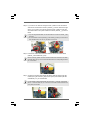
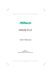
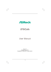
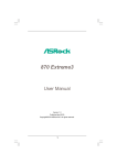
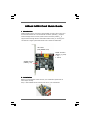
ASR
ock SA
ASRock
SATTA3 Card Quick Guide
I. Introduction
ASRock SATA3 Card is composed of three SATAIII connectors which allow up to
6.0 Gb/s data transfer rate. The red eSATAIII connector (eSATAIII_1) supports
external storage devices, and the yellow SATAIII connectors (SATAIII_1_2)
support internal storage devices. With ASRock SATA3 Card, you can enjoy the
convenience of higher speed data transfer rate on ASRock motherboard.
LED header
(LED_HEADER, black)
SATAIII connectors
(SATAIII_1_2, yellow)
1: top
2: bottom
eSATAIII connector
(eSATAIII_1, red)
II. Installation
Before you install ASRock SATA3 Card on your motherboard, please refer to
below steps carefully.
Step 1. Insert ASRock SATA3 Card into PCIE slot on your motherboard.
1
Step 2. If you want to use external storage function, please connect the eSATA
cable to the red eSATAIII connector (eSATAIII_1) and the external storage
device. If you want to use internal storage function, please connect the
SATA data cables to the yellow SATAIII connectors (SATAIII_1_2) and the
HDDs.
1. If you use single SATAIII HDD, it is recommended to connect it to SATAIII_1 (top)
connector.
2. The red eSATAIII connector (eSATAIII_1) and SATAIII_2 (bottom) connector cannot
work simultaneously. You can only use either one of them.
or
Step 3. Connect the chassis HDD LED lead to ASRock SATA3 Card LED header
(HDLED-_CHA and HDLED+_CHA).
Before connecting, please consult the chassis manual for the electrode of the HDD
LED lead. Make sure you connect the HDD LED lead to the corresponding electrode
pin of LED header.
Step 4. Connect the bundled motherboard LED lead to ASRock SATA3 Card LED
header (LED-_MB and LED+_MB) and the system panel header (HDLEDand HDLED+) on your motherboard.
For the bundled motherboard LED lead, the blue lead is “+” electrode, and the black
lead is “-” electrode. Make sure you connect the correct lead to ASRock SATA3 Card
and system panel header.
2