1
INDEX
Precaution Notice ............................................................................................ 1
ENERMAX PRO87+ series Power Supply Specification.............................. 2
ENGLISH........................................................................................................ 3
DEUTSCH ...................................................................................................... 7
ESPAÑOL ..................................................................................................... 11
FRANCAIS ................................................................................................... 15
ITALIANO .................................................................................................... 19
РУССКИЙ .................................................................................................... 23
POLSKI......................................................................................................... 27
Precaution Notice
Only a technician, authorized by ENERMAX, is allowed to perform maintenance service! Warranty
is subject to void under unauthorized attempt to open the power case or modification of any kinds,
even attempted only, of the power supply or its components!
ENERMAX will not be responsible for damages caused by following situations:
Opening of the PSU case and/or modification of any component or cable without ENERMAX’
written authorization.
Ignoring connector’s wrong insertion prevention design by attaching a connector to a device in
wrong orientation.
Connecting too many devices to one cable unit by using additional adaptor (Y cables).
Damage caused by natural phenomena or uncontrollable forces, such as lightning, flooding, fire,
earthquake, etc.
This ENERMAX Technology Corporation product is warranted to be free from defects in material
and workmanship for a period of five (5) years from the date of purchase. ENERMAX Technology
Corporation agrees to repair or replace the product, at its own option and at no charge, if, during the
warranty period, it is returned to nearest ENERMAX Technology Corporation subsidiary/agent with
all shipping charges prepaid and bearing a return merchandize authorization (RMA) number, and if
inspection reveals that the product is defective. Charges for removing or installing the product are
excluded under the terms of this warranty agreement. This warranty shall not apply to any product,
which has been subject to connection to a faulty power source, alteration, negligence, or accident, or
to any product, which has been installed other than in accordance with these instructions. In no event
shall ENERMAX Technology Corporation, or its subsidiaries, or agents be liable for damages for a
breach of warranty in an amount exceeding the purchase price of this product!
If you are uncertain whether or not your ENERMAX PSU is defective, please contact your
dealer/reseller for support!
Web Site: www.enermax.com
E-mail: [email protected]
Forum: forum.enermax.com
ENERMAX Technology Corporation, 15F-2, No. 888, Jing-Guo Road, Taoyuan City (330),
Taiwan (R.O.C.)
Tel. +886-3-316-1675
Fax. +886-3-346-6640
©2009 ENERMAX Technology Corporation. All rights reserved. Specifications are subject to change without
prior notice. Actual product and accessories may differ from illustrations. Omissions and printing errors
excepted. Content of delivery might differ in different countries or areas. Some trademarks may be claimed as
the property of others. Reproduction in any manner without the written permission of ENERMAX is strictly
forbidden.
1
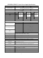
ENERMAX PRO87+ Series Power Supply Specification
EPG500AWT
EPG600AWT
EPG700AWT
100-240VAC, 50-60Hz
(Maximum range:90-265VAC, 47-63Hz)
6.5 – 3A
8 – 3.5A
9 – 4A
AC Input Voltage
AC Input Current
DC Output
Rated
3.3V
5V
12V1
12V2
12V3
-12V
5Vsb
Total Power
Peak Power
Combined
0-20A
0-20A
0-25A
0-25A
0-25A
0-0.5A
0-3A
100W
492W
(41A)
6W
15W
500W
550W
Rated
0-24A
0-24A
0-25A
0-25A
0-25A
0-0.5A
0-3A
Combined
120W
600W
(50A)
6W
15W
600W
660W
Rated
0-24A
0-24A
0-25A
0-25A
0-25A
0-0.5A
0-3A
Combined
120W
696W
(58A)
6W
15W
700W
770W
Protection Circuit
Over Current Protection
Over Voltage Protection
(DC)
Under Voltage Protection
(AC)
Under Voltage Protection
Over Power Protection
Over Temperature Protection
Short Circuit Protection
Surge & Inrush Protection
DC Rail
3.3V
5V
12V
DC Rail
3.3V
5V
12V
DC Rail
3.3V
5V
12V
OCP trigger range
30 – 40A
30 – 40A
30 – 40A
OVP trigger range
3.7-4.1V
5.7-6.5V
13.1-14.5V
UVP trigger range
2.0 – 2.4V
3.3 – 3.7V
8.5 – 9.5V
Activated when AC input voltage < 70VAC.
Activated when output power > 120 ~150% of rated max load.
Activated when PSU heat sink > 90 ~ 120oC.
Activated when any DC rails short-circuited.
Sustain 2KV surge stroke.
Sustain up to 48A inrush current @ 240VAC at cold start.
ENVIRONMENT
Temperature
Humidity
Cooling
MTBF
Dimension
Weight
Safety
EMC
Operation ambient: 0~50oC (for full rated output)
Storage ambient: -40~70 oC
Operation: to 85% relative humidity, non-condensing at 25 oC
Storage: to 95% relative humidity, non-condensing at 50 oC
OTHERS
One 13.9cm twister bearing fan, speed auto controlled.
> 100,000 hours at 70% of full rated load, 230VAC/50Hz, 25 oC
(MIL-HDBK-217F standard)
150 (w) x 86 (h) x 160 (d) mm
2.35kg ±150g
UL/cUL(Level 6), TUV, CCC, GOST, CB, BSMI
CE, FCC, KCC
2
User’s Manual
Dear customer,
Thank you for choosing this ENERMAX PRO87+ power supply unit (PSU)! Please read this manual
carefully and follow its instructions before installing the PSU.
We would like to draw your attention that a computer required very specific conditions to work best
for you without failing. To avoid failures and to increase lifetime of the system, we suggest that:
Your system is NOT located near a radiator or any other heat producing device.
Your system is NOT located near a magnetic device.
Your system is NOT located in a moist and/or dusty and/or vibrating environment.
Your system is NOT exposed to direct sunshine.
Your system is sufficiently cooled by additional fans.
If you use AC extension cables, please make sure it can support all connected appliances’
potential peak power draw. Or redistribute other high power consumption equipment, such as
laser printers or monitors to other AC wall outlets. Exceeding the extension cable’s loading
capacity could trigger its circuit breaker and cut off the power.
If you want to add the UPS (Uninterruptible Power Supply) for your system, please choose
adequate Watts/VA capacity UPS. Ex.
PSU Model
Suggested minimum UPS output power capacity
(Based on efficiency & PFC at respective load)
EPG500AWT
EPG600AWT
EPG700AWT
600W / 1000VA
700W / 1100VA
800W / 1200VA
* If you intend to add other appliance powered by the same UPS, such as monitor or printer,
please use higher capacity UPS according to all connected devices’ rated power draw.
* Please do not mistake VA capacity as Watts, or use insufficient power UPS. This would result
in less UPS battery runtime or the inability to power the system in battery mode.
COMPATIBILITY
ENERMAX PRO87+ series is compliant with:
Intel ATX12V Power Supply Design Guide v2.3 specification and downward compatible with
v2.0, v2.01 and v2.2
ATX System Design Guide v2.2, v2.1
BTX/ EEB/ CEB/EPS12V
This PSU does not support MB with ISA expansion slot, which might require –5V power. –5V has
been cancelled from Intel ATX12V v1.3 specification onwards.
3
ENGLISH
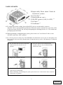
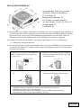
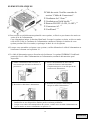
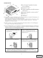
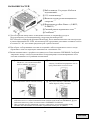
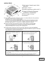
NAME OF PARTS
1Output cable: Please check “Cables &
Connectors” section.
2 13.9cm fan.# 1
3 Honeycomb air vent. # 1
4 ON/OFF switch: (I=ON, O=OFF). # 2
5 AC Inlet. # 2
6 CordGuard. # 3
#1 To ensure best system cooling, do not block PSU fan’s air in-take and air vent area.
This PSU offers a special HeatGuard function. When the system is turned off, or goes into ACPI
S3/S4 sleep mode, the PSU fan will keep dissipating the remaining heat for 30 ~ 60 seconds and
prolonging system lifetime.
#2 When assembling or maintaining the system, please remove AC cord from AC inlet, or turn
ON/OFF switch into “OFF” position.
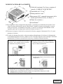
#3 AC cord can get loose in many ways. The ENERMAX CordGuard lock can fix your AC cord tightly to the
PSU, so that it will not be easily detached and avoid shut-downs of your PC. The following is CordGuard
installation:
① Set your PSU into the chassis, and please
② Press two sides of the CordGuard lock
make sure the I/O switch is on “O”
position.
③ Plug the AC cord into your PSU.
together, and set it into CordGuard holder
near the AC inlet.
④ Lock CordGuard to latch onto AC cord.
1. CordGuard is for AC cords supplied with ENERMAX CordGuard-compatible PSUs. Other AC
cords may be incompatible.
2. When assembling or maintaining the system, please remove AC cord from AC inlet, or turn I/O
switch into “O” position.
4
ENGLISH
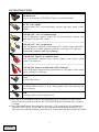
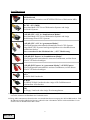
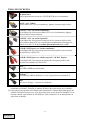
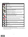
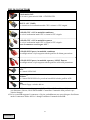
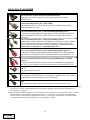
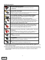
CONNECTOR TYPES
24P Mainboard
For new generations of ATX/EEB/CEB server/workstation MB.
8P CPU +12V (700W)
Supports multi-CPU server/workstation systems and some single socket
systems.
4+4P (8P) CPU +12V, in combined mode
8-pin configuration supports multi-CPU server/workstation systems and
some single extreme CPU systems.
4+4P (8P) CPU +12V, in split mode
4-pin configuration supports certain single CPU systems. Some multi-CPU
workstation/server system might also need this extra 4-pin 12V connector.
Please use the connector with “12V” marking.
6+2P (8P) PCI Express, in combined mode
8-pin configuration supports latest extreme graphic cards, which require
8-pin PCI-E connector.
6+2P (8P) PCI Express, in split mode / 6P PCI Express
6-pin configuration supports most performance PCI-E graphic cards, which
require 6-pin PCI-E connector.
SATA # 1
For SATA/SAS drives.
4P Molex # 2
For IDE/SCSI/SAS drives or some AGP graphic card with traditional 4P
power in socket.
FDD
For floppy drive or certain add-on card.
#1 Some SATA drives might accept SATA or 4P Molex power. Normally, use either one of
power connector to power the driver, BUT NOT BOTH! Please check the drive’s manual
or details.
#2 Some MB might require this connector to share the +12V current from 24-pin Mainboard
connector to PCI-E slot. If your MB already supports 24-pin Mainboard connector, you
may not need to add the 4P Molex connector on it. Please check the MB’s manual for details.
5
ENGLISH
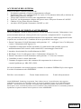
BOOTING YOUR SYSTEM
Before booting your system, please check that:
1. Main power connector (24P) is properly connected.
2. CPU +12V power connector (4 or 8-pin configuration), and/or a 4P Molex connector (if required
by MB) is properly connected.
3. All other needed connectors are properly connected.
4. AC cord is properly connected to wall outlet and PSU AC inlet.
5. Close your system chassis.
6. Turn on the PSU by switching the ON/OFF switch to “ON”, and your system is ready.
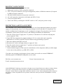
PROTECTION, SAFETY & SECURITY
This ENERMAX PSU features multiple protections. In case of most abnormal situations, the power
supply will automatically turn off to avoid potential danger to itself and other PC components. It is
usually a malfunction of components or user’s negligence to trigger off a protection event. In such
circumstance, please check your PC devices and working environment for malfunction:
1. Turn I/O switch of power supply into “O” position, or disconnect AC cord from wall plug and
power supply AC inlet.
2. Check PSU for temperature by simply touching it. If it is very hot, this can be caused by
malfunction of case fans or the PSU fan itself and/or wrong positioning of your PC.
3. Wait some minutes until PSU cools off.
4. Reconnect AC cord to wall plug and power supply AC inlet.
5. Turn I/O switch of power supply into “I” position, and reboot your system.
6. Check, if all fans are working.
7. Contact technical support of the respective manufacturer of the component which you think might
be the cause to the problem. (e.g. MB, GPU or PSU)
If you have any question or need support, please contact your reseller or nearest ENERMAX
subsidiary/agent or ENERMAX headquarter service center.
Web Site: www.enermax.com
Forum: forum.enermax.com
E-mail: [email protected]
©2009 ENERMAX Technology Corporation. All rights reserved. Specifications are subject to change without
prior notice. Actual product and accessories may differ from illustrations. Omissions and printing errors
excepted. Content of delivery might differ in different countries or areas. Some trademarks may be claimed as
the property of others. Reproduction in any manner without the written permission of ENERMAX is strictly
forbidden.
6
ENGLISH
Benutzerhandbuch
Sehr geehrte Kundin, sehr geehrter Kunde,
Vielen Dank, dass Sie sich für dieses ENERMAX PRO87+-Netzteil (PSU) entschieden haben! Bitte
lesen Sie sich dieses Handbuch sorgfältig durch und folgen Sie bitte seinen Anweisungen bevor Sie
das Netzteil installieren!
Wir möchten Sie darauf hinweisen, dass moderne Systeme sehr empfindlich geworden sind und
genau definierte Bedingungen benötigen, um optimal ohne Ausfälle arbeiten zu können. Um solche
Ausfälle zu vermeiden und die Lebensdauer Ihres Systems zu verlängern, empfehlen wir Ihnen
sicherzustellen, dass:
Ihr System nicht neben einer Heizung oder einer anderen Wärmequelle steht.
Ihr System nicht neben einer magnetischen Quelle steht.
Ihr System nicht in einer feuchten und/oder staubigen und/oder vibrierenden Umgebung steht.
Ihr System nicht dem direkten Sonnenlicht ausgesetzt ist.
Ihr System ausreichend durch Lüfter gekühlt wird.
Falls Sie ein Verlängerungskabel verwenden, stellen Sie bitte sicher, dass dieses dazu geeignet ist, den
maximalen Strombedarf sämtlicher angeschlossener Geräte zu leisten. Andernfalls schließen Sie bitte
weitere viel Strom verbrauchende Geräte (wie Laserdrucker oder Monitor) an eine andere Steckdose an.
Ein Überschreiten der maximalen Durchleitungsfähigkeit des Verlängerungskabels könnte zu einem
Auslösen der Sicherung führen.
Falls Sie eine USV (Unterbrechungsfreie Stromversorgung) verwenden möchten, nutzen Sie bitte eine
mit ausreichender Watt/VA-Kapazität. Z. B.:
PSU Modell
Empfohlene kleinste USV-Kapazität
(gemäß Effizienz & PFC bei entsprechender Last)
EPG500AWT
EPG600AWT
EPG700AWT
600W / 1000VA
700W / 1100VA
800W / 1200VA
* Falls Sie andere Geräte wie Monitor oder Drucker gleichfalls an die USV anschließen möchten,
wählen Sie bitte eine USV mit höherer Kapazität gemäß der Summe der Leistungsaufnahme aller
angeschlossenen Geräte.
* Bitte verwechseln Sie nicht VA mit Watt und nutzen Sie bitte eine ausreichende USV. Andernfalls
verkürzt sich die Laufzeit der Batterie und gefährdet die Versorgung des Systems im Batterie-Modus.
KOMPATIBILITÄT
ENERMAX PRO87+ PSU Serie ist kompatibel mit:
Intel ATX12V Power Supply Design Guide v2.3 Spezifikation und abwärtskompatibel mit v2.0, v2.01,
v2.2.
ATX System Design Guide v2.2, v2.1.
BTX / EEB / CEB / EPS12V.
Dieses Netzteil unterstützt keine MB`s mit ISA Erweiterungsslots, welche -5V benötigen könnten.
-5V wurde ab Intel ATX12V v1.3 Spezifikation abgeschafft.
7
DEUTSCH
DETAILBESCHREIBUNG
①Ausgangskabel: Bitte lesen Sie den
Abschnitt „Kabel & Anschlüsse“.
②13.9cm Lüfter. #1
③Honigwabenluftauslass. #1
④I/O Schalter: separater NetzteilAn/Aus-Schalter (I=AN, O=AUS). #2
⑤Stromeingang. #2
⑥CordGuard. #3
#1 Bitte blockieren Sie nicht die Lufteinlässe/Luftauslässe, um eine bestmögliche Systemkühlung zu
gewährleisten. Dieses PSU verfügt über eine besondere HeatGuard-Funktion: Wenn das System
abgeschaltet oder in den ACPI-S3/S4-Schlafmodus gebracht wird, wird der PSU-Lüfter die
Restwärme für 30-60 Sek. abführen und so die Lebensdauer des Systems verlängern.
#2 Entfernen Sie immer das Stromkabel vom Netzteil und schalten Sie den I/O-Schalter auf
„O“ während Sie am System arbeiten.
#3 Der Netzstecker kann sich auf unterschiedliche Weise lösen. Der ENERMAX-CordGuard fixiert
den Stecker am Netzteil. Er verhindert unfreiwillige Systemabstürze durch einen versehentlich
gezogenen Netzstecker:
① Setzen Sie das Netzteil in das Gehäuse ein. ② Drücken Sie die beiden Seiten des CordGuard
Stellen Sie sicher, dass der Netzschalter auf
“O“ (Aus) steht.
③ Schließen Sie das Netzkabel am Netzteil
zusammen und befestigen Sie ihn an der dafür
vorgesehenen Stelle.
④ Klappen Sie den CordGuard herunter und
an.
sichern Sie auf diese Weise den Netzstecker.
1. Der CordGuard ist nur für Netzkabel geeignet, die mit CordGuard-kompatiblen
ENERMAX-Netzteilen ausgeliefert wurden. Andere Netzkabel sind mit dem
ENERMAX-CordGuard ggf. nicht kompatibel.
2. Beim Zusammenbauen oder bei der Wartung des Systems ziehen Sie bitte immer den
Netzstecker oder stellen Sie den Netzschalter auf “O“(Aus).
8
DEUTSCH
Anschlusstypen
24P Mainboard
Für die neueste Generation von ATX/EEB/CEB Server/Workstation MB’s.
8P CPU +12V (700W)
Unterstützt Multi-CPU Server/Workstation-Systeme und einige
Ein-Sockel-Systeme.
4+4P (8P) CPU +12V, in “kombiniertem Modus”
Unterstützt Multi-CPU Server/Workstation-Systeme und einige
Hochleistungs-Einzel-CPU-Systeme.
4+4P (8P) CPU +12V, in “getrenntem Modus”
4-Pin Konfiguration unterstützt herkömmliche Einzel-CPU-Systeme.
Einige Multi-CPU-Systeme benötigen möglicherweise ebenfalls diesen
zusätzlichen Stecker.
Bitte verwenden Sie das Modul mit der „+12V” Markierung.
6+2P (8P) PCI Express, in “kombiniertem Modus”
8-Pin Konfiguration unterstützt die neuesten Grafikkarten, welche diesen
8-Pin PCI-E Stecker benötigen.
6+2P (8P) PCI Express, in “getrenntem Modus” / 6P PCI Express
6-Pin Konfiguration unterstützt die meisten Grafikkarten, welche diesen
6-Pin PCI-E Stecker benötigen.
SATA # 1
Für SATA/SAS-Laufwerke.
4P Molex # 2
Für IDE/SCSI/SAS-Laufwerke oder einige AGP Grafikkarten mit
traditionellem 4-Pin Stecker.
FDD
Für Floppy-Laufwerke oder einige Erweiterungskarten.
#1 Einige SATA-Laufwerke unterstützen SATA- & 4-Pin-Molex-Stecker. Schließen Sie nur einen Stecker an!
Lesen Sie ansonsten im Handbuch des Laufwerks nach!
#2 Einige MB´s unterstützen diesen Stecker zur zusätzlichen Stromversorgung des 20-Pin-MB-Steckers. Falls
Ihr MB einen 24-Pin-MB-Sockel besitzt, sollten Sie den 4-Pin-Molex-Stecker nicht anschließen. Lesen
Sie dies bitte im Handbuch des MB´s nach!
9
DEUTSCH
EINSCHALTEN IHRES SYSTEMS
Vor dem Einschalten Ihres Systems stellen Sie bitte sicher, dass:
1. Mainboard-Stromanschluss (24P) korrekt angeschlossen ist.
2. CPU +12V ATX Stromanschluss (4 oder 8 Pin Konfiguration) (falls für MB erforderlich)
korrekt angeschlossen ist, oder ein 4-Pin Molex-Stromanschluss (falls für MB erforderlich)
korrekt angeschlossen ist.
3. Alle anderen erforderlichen Stromanschlüsse korrekt angeschlossen sind.
4. Kaltgerätekabel (Stromkabel) korrekt an Steckdose und Netzteil angeschlossen ist.
5. Das SystEPGehäuse verschlossen und verschraubt ist!
6. Drücken Sie am Netzteil den I/O-Schalter auf “I” (ON). Das System ist jetzt bereit!
SICHERHEITSFUNKTIONEN
Dieses ENERMAX PRO87+ Netzteil verfügt über zahlreiche Sicherheitsfunktionen. Im Fall der
meisten abnormen Situationen wird sich das Netzteil zum Schutz Ihres gesamten PC-Systems
automatisch abschalten, um Schäden zu vermeiden. In den meisten Situationen, in denen dies
geschieht, ist eine Komponenten-Fehlfunktion oder Fehlverhalten die Ursache. In einer solchen
Situation prüfen Sie bitte zuerst ihre PC-Komponenten und die Umgebung auf Fehlfunktion(en),
indem Sie folgendes ausschalten und/oder abtrennen:
1. I/O Schalter des Netzteils auf “O“ & Kaltgerätekabel (Stromkabel) von der Steckdose und vom
Netzteil trennen.
2. Berühren Sie das Netzteil vorsichtig, um zu prüfen, ob es stark erhitzt ist. Sollte dies der Fall sein,
kann es eine Folge der Fehlfunktion von Gehäuse-oder Netzteillüftern sein oder durch eine
ungenügende Anzahl von Gehäuselüftern oder eine falsche PC-Positionierung verursacht worden
sein.
3. Warten Sie einige Minuten, bis sich das Netzteil abgekühlt hat.
4. Schliessen Sie wieder das Kaltgerätekabel (Stromkabel) an Steckdose und Netzteil an.
5. Schalten Sie den I/O-Schalter am Netzteil auf “I”.
6. Prüfen Sie nun, ob alle Lüfter Ihres Systems arbeiten.
7. Kontaktieren Sie bitte den technischen Support des Herstellers der Komponente, von der Sie
glauben, dass Sie die Fehlfunktion verursacht (z.B. MB, Grafikkarte oder ENERMAX-Netzteil).
Falls Sie Fragen haben oder Support benötigen, wenden Sie sich bitte an ihren Händler, an ihre
nächste ENERMAX-Niederlassung, deren Agenten oder an das ENERMAX Headquarter Service
Center! Schnelle Hilfe bei allen Fragen zu ENERMAX-Produkten erhalten Sie auch online im
internationalen ENERMAX-Support-Forum: http:\\forum.enermax.com.
Web Site: www.enermax.de
E-mail: [email protected]
Forum: forum.enermax.com
Die Informationen in diesem Dokument unterliegen unangekündigten Änderungen.
©2009 ENERMAX Technology Corporation. Alle Rechte vorbehalten.
Die Vervielfältigung dieses Dokuments in jeglicher Form ist ohne schriftliche Genehmigung durch
ENERMAX streng untersagt.
10
DEUTSCH
Manual Del Usuario
Estimado cliente:
Muchas gracias por comprar nuestra fuente ENERMAX PRO87+. Le recomendamos que se lea bien
este manual para el usuario.
Queremos recordarle que los ordenadores actuales son muy vulnerables y necesitan condiciones
especiales para funcionar sin problemas. Para evitar dichos fallos y maximizar la duración del
sistema, le recomendamos que se asegure de:
Su ordenador no se encuentre al lado de la calefacción ni otro objeto que irradie calor.
Su ordenador no se encuentre al lado de un objeto magnético.
Su ordenador no se encuentre en un entorno húmedo, con polvo y vibraciones.
Su ordenador no reciba radiación solar directa.
Su ordenador sea refrigerado lo suficiente por parte de los ventiladores.
Si utiliza un cable prolongador no lo puede utilizar con otros equipos de alto consumo de
corriente, como impresoras LASER para asegurarse de que no sobrepasa la corriente máxima
del cable, o conecte los equipos a otra toma de corriente.
Si utiliza un SAI (Sistemas de Alimentación Ininterrumpida) para su sistema, debe emplear uno
con capacidad de vatios-VA suficiente como:
modelo de la fuente
Capacidad recomendada mínima del SAI:
(se basa por eficiencia y PFC a carga respectiva)
EPG500AWT
EPG600AWT
EPG700AWT
600W / 1000VA
700W / 1100VA
800W / 1200VA
* Si quiere enchufar otros equipos como una impresora o monitor, tiene que usar un modelo
con capacidad mayor.
* Por favor, no confunda capacidad de VA con vatios ni utilice un SAI insuficiente, ya que
provocaría una disminución de la duración SAI o problemas el encender el sistema en
modalidad de batería.
COMPATIBILIDAD
La serie ENERMAX PRO87+ fuente es compatible con:
Intel ATX12V Power Supply Design Guide especificación v2.3 y también con las versiones
v2.2, v2.01 e v2.2
ATX System Design Guide v2.2, v2.1
BTX / EEB / CEB / EPS12V
Si su Placa base (MB) utiliza un bus “ISA“, es posible que esta fuente no sea compatible, porque no
tiene una transmisión de -5V, requerida por algunos equipos de ISA. La transmisión de -5V fue
desplazada por Intel ATX12V v1.3!
11
ESPAÑOL
NOMENCLATURA DE LAS PARTES
①Cable del corriente: Por favor, examine el
párrafo „CABLES Y ENCHUFES”.
②Ventilador de 13.5 cm.# 1
③Honeycomb air vent. # 1
④Interruptor I/O*: separado interruptor de la
fuente por En/Paro (I=En, O=Paro). # 2
⑤Toma de corriente # 2
⑥CordGuard # 3
#1 Para asegurar la mejor refrigeración del sistema., no obstruya la ventilación de la fuente. Esta
fuente le ofrece una función especial “HeatGuard”.Cuando el sistema está apagado o está en
modo ACPI S3/S4, el ventilador de la fuente va a desviar el calor hacia fuera durante 30-60
segundos para bajar la temperatura media del sistema en unos 3-5 oC.
#2 Desconecte siempre el cable de la corriente de la fuente y apague el interruptor I/O a “O“ para
mantener el sistema.
#3 El cable de alimentación puede ser desconectado accidentalmente de la fuente de alimentación
ocasionando apagados sin aviso y daños en el PC, Enermax dispone de la tecnología CordGuard
manteniendo el conector en su posición correcta y evitando accidentes fortuitos..
①Aloje dentro de la misma fuente el propio
②Presione al mismo tiempo las dos solapas de
conector, y así se asegura de que el conector
se mantiene en la posición correcta.
③ Conectar el cable a la fuente.
CordGuard e inserte lo en los huecos donde se
aloja el cable de alimentación.
④ Cierre CordGuard haciendo presión. Esto
permite tener siempre en la posición correcta
el dispositivo..
1. CordGuard es un sistema exclusivo de la marca Enermax, cualquier intento de
instalación en otro dispositivo distinto puede ocasionar problemas.
2. Cuando se hace mantenimiento del sistema con operaciones internas, el cable
SIEMPRE debe permanecer desconectado.
12
ESPAÑOL
TIPOS DE ENCHUFES
24P placas base
Soporta generaciones nuevas de ATX/EEB/CEB server/workstation.
8P CPU +12V (700W)
Soporta multi-CPU server/workstation y algunos sistemas single-socket.
4+4P CPU +12V, en “modo combinado”
La configuración 8-Pin soporta multi-CPU server/workstation y algunos
sistemas single-socket extremas.
4+4P CPU +12V, en “modo separado”
La configuración 4-Pin soporta la mayoría de los sistemas single-socket.
Unos sistemas multi-CPU server/workstation posiblemente necesitan este
enchufe de 4-Pin 12V. Use el enchufe parcial marcado con “+12V”.
6+2P (8P) PCI Express, en “modo combinado”
La configuración 8-pin soporta las nuevas tarjetas gráficas, que necesitan
este enchufe de 8-Pin PCI-E.
6+2P (8P) PCI Express, en “modo separado” / 6P PCI Express
La configuración 6-pin soporta la mayoría de las tarjetas gráficas, que
necesitan este enchufe de 6-Pin PCI-E.
SATA # 1
Para ODD o HDD tipo SATA/SAS.
4P Molex # 2
Para ODD tipo IDE/SCSI/SAS de ”vieja” generación con enchufe 4-P.
FDD
Para discos “Floppy” ó tarjetas de expansión.
#1 Unos discos duros de SATA soportan conectores SATA e 4-Pin Molex. Conecte Vd.
solamente un enchufe! Examine su manual del disco duro para entrar más en detalle.
#2 Unas placas base soportan este enchufe para suministrar corriente addicional aparte del
enchufe 24-Pin de la placa base. Si su placa base tiene un zócalo de 24-Pin MB, Vd. no
debería conectar este enchufe de 4-Pin Molex. Debe examinar Vd. su manual sobre la
placa base en detalle.
13
ESPAÑOL
ENCENDIENDO EL SISTEMA
Antes de encenderlo por favor asegúrese de que:
1. El enchufe de la placa base está conectado correctamente.
2. El enchufe de la CPU +12V AUX (si es necesario) esté conectado correctamente.
o un enchufe 4-Pin Molex (si es necesario) esté conectado correctamente.
3. Todos los otros enchufes necesarios están conectado correctamente.
4. El cable de la corriente (AC) está conectado correctamente con la fuente y el enchufe!
5. Cierre la caja del sistema!
6. Coloque el interruptor de la fuente en la posición “I”.
FUNCIÓNES DE PROTECCIÓN Y SEGURIDAD
La fuente ENERMAX PRO87+ tiene varias funciones de protección y seguridad. En caso de mal
funcionamiento se detendrá para proteger todo el sistema de daños. En la mayoría de casos eso será
causado por un mal funcionamiento de componentes o mala utilización. En cualquier situación
siempre sigua las instrucciones y desconéctela o apáguela:
1. El interruptor de la fuente por “O“ y el cable corriente (AC) del enchufe y de la fuente.
2. Todos los componentes, que no son absolutamente necesarios, como ODD. Examine su
temperatura por medio del tacto. Si está caliente, puede ser, que los ventiladores del sistema o de
la fuente estén dañados o su caja no tenga ventiladores suficientes o es en una mala posición. (Lea
nuestras recomendaciones en el comienzo del manual).
3. Espere. por unos minutos hasta que la fuente se haya enfriado.
4. Conecte de nuevo el cable corriente (AC) con enchufe y fuente.
5. Ponga el interruptor de la fuente en “I”.
6. Examine Si todos los ventiladores están trabajando.
7. Contacte. el fabricante del componente si piensa que está causando el problema.
(como tarjetas o ENERMAX).
Si tiene preguntas o si necesita ayuda, por favor contacte su vendedor, una sucursal de ENERMAX,
o el centro mundial de soporte de ENERMAX.
Web Site: www.enermax.com
E-mail: [email protected]
Forum: forum.enermax.com
La información contenida en este documento está sujeta a cambios sin previo aviso.
©2009 ENERMAX Technology Corporation. Reservados todos los derechos. Se prohíbe estrictamente la
reproducción de este documento en cualquier forma sin permiso en escrito de ENERMAX.
14
ESPAÑOL
Manuel d’utilisateur
Chers clients,
Merci d’avoir choisi l’alimentation ENERMAX PRO87+! Veuillez lire avec attention ce manuel
avant de procéder à l’installation de l’alimentation.
Nous souhaiterions attirer votre attention sur le fait qu’un ordinateur est fragile et demande de
respecter certaines conditions pour fonctionner de façon optimale. Pour éviter tout problème et
augmenter la durée de vie de votre système, nous vous suggérons de :
Ne pas placer votre système près d’un radiateur ou de toute autre source de chaleur.
Ne pas placer votre système près d’une source magnétique.
Ne pas placer votre système dans une pièce humide, et/ou salle, et/ou un environnement soumis
à des vibrations.
Ne pas exposer votre système à la lumière directe du soleil.
Refroidir suffisamment votre système par l’ajout de ventilateurs supplémentaires si nécessaire.
Si vous utilisez une rallonge électrique, assurez-vous qu’elle puisse supporter le courant
nécessaire au bon fonctionnement de tous les appareils connectés. Sinon déportez le
branchement des appareils à forte consommation électrique sur une autre prise murale. Si vous
dépassez les capacités de charge maximale supportées par votre câble électrique, vous risquez
de couper l’alimentation.
Si vous souhaitez ajouter un onduleur à votre système, veuillez à choisir la capacité Watts/VA
adéquate. Ex.
Modèle d’alimentation
EPG500AWT
EPG600AWT
EPG700AWT
Capacité minimale suggérée pour votre onduleur
600W / 1000VA
700W / 1100VA
800W / 1200VA
* Si vous souhaitez brancher plusieurs autres appareils à votre onduleur, comme une imprimante ou un
moniteur, veillez à choisir une capacité en courant plus élevée.
* Assurez vous que les capacités de votre onduleur en watts et VA soient suffisante, sans quoi
votre réserve d’énergie sera fortement réduite ou simplement nulle en cas de coupure de
courant.
COMPATIBILITE
La série ENERMAX PRO87+ est compatible avec:
Les spécifications Intel ATX12V Power Supply Design Guide v2.3 et les versions antérieures v2.0, v2.01
et v2.2
ATX System Design Guide v2.2, v2.1
BTX/ EEB/ CEB/EPS12V
Cette alimentation ne supporte pas les cartes mères avec un slot ISA, qui pourrait demander une
source d’alimentation -5V. Cette dernière a été retirée des spécifications Intel ATX12V v1.3.
15
FRANCAIS
ELEMENTS PRATIQUES
1Câble de sortie: Veuillez consulter la
section ‘‘Câbles & Connecteurs’’.
2 Ventilateur de 13.9cm.# 1
3 Ventilation en Nid d’abeille. # 1
4 Bouton ON/OFF: (I=ON, O=OFF). # 2
5 Connecteur AC. # 2
6 CordGuard. # 3
#1 Pour assurer un refroidissement optimal de votre système, veillez à ne pas obstruer les entrées et
sorties d’air de l’alimentation.
Cette alimentation intègre la fonction HeatGuard. Lorsque le système est éteint, ou bien en mode
veille ACPI S3/S4, le ventilateur de l’alimentation continuera à dissiper la chaleur de votre
système pendant 30 à 60 secondes, et prolonger la durée de vie du système.
#2 Lorsque vous assemblez ou réparez votre système, veuillez débrancher le câble d’alimentation ou
bien mettre le bouton sur la position ‘O’.
#3 Le câble d’alimentation peut se décrocher très facilement. Le système ENERMAX CordGuard
permet de fixer le câble d’alimentation sur l’alimentation, rendant la déconnexion quasi
impossible.
① Mettre l’alimentation dans le boîtier, et
② Insérer simultanément les deux côtés du
vous assurer que le bouton est bien sur la
position”O”.
③ Brancher le câble dans l’alimentation.
système de fixation CordGuard dans
l’emplacement prévu à cet effet proche du
connecteur d’alimentation.
④ Refermer le système CordGuard pour
bloquer le câble d’alimentation.
1. CordGuard es un sistema exclusivo de la marca Enermax, cualquier intento de
instalación en otro dispositivo distinto puede ocasionar problemas.
2. Lorsque vous réalisez des manipulations du système, veuillez retirer le câble d’alimentation de
la prise murale ou mettre l’alimentation en position ‘O’.
16
FRANCAIS
CONNECTOR TYPES
24P Carte Mère
Pour la nouvelle génération de cartes mères serveur et stations de travail
ATX/EEB/CEB.
8P CPU +12V (700W)
Pour les serveurs et stations de travail multi-CPU et certaines mono CPU.
4+4P (8P) CPU +12V, en mode combiné
La configuration 8-pins supporte les serveurs et stations de travail
multi-CPU et certaines mono CPU.
4+4P (8P) CPU +12V, en mode séparé
La configuration 4-pins supporte les systèmes mono CPU. Certaines
stations de travail ou serveurs multi-CPU pourraient avoir besoin de ce
connecteur 4-pins 12V supplémentaire.
Veuillez utiliser le connecteur marqué“12V”.
6+2P (8P) PCI Express, en mode combiné
La configuration 8-pins supporte les dernières cartes graphiques PCI-E.
6+2P (8P) PCI Express, en mode séparé / 6P PCI Express
La configuration 6-pins supporte la plupart des cartes graphiques PCI-E.
SATA # 1
Pour les disques durs/ lecteurs optique SATA/SAS.
4P Molex # 2
Pour les disques durs/ lecteur optique IDE/SCSI/SAS ou quelques cartes
graphiques AGP.
FDD
Pour lecteur de disquette.
#1 Certains disques dures SATA peuvent accepter une alimentation SATA ou 4P Molex. Utiliser l’un
des deux connecteurs, et JAMAIS les deux en même temps.
#2 Certaines cartes mères nécessitent de partager le connecteur 12V. Si votre carte mère supporte
déjà le connecteur 24P, il n’est pas nécessaire d’ajouter le 4P Molex. Vérifier le manuel de votre
carte mère pour plus d’informaton.
17
FRANCAIS
DEMARRER VOTRE SYSTEME
Avant de démarrer votre système, veuillez vérifier les points suivants:
1. Le connecteur d’alimentation principal est correctement branché (24P).
2. Le connecteur CPU +12V (4P ou 8P), et/ou le connecteur 4P Molex (si nécessaire) sont correctement
branchés.
3. Tous les autres connecteurs nécessaires sont correctement branchés.
4. Le cordon d’alimentation doit être connecté à la prise électrique murale et à l’alimentation.
5. Fermer le boîtier de votre système.
6. Placer le bouton ON/OFF de l’alimentation sur la position ‘ON’ et votre système est prêt à démarrer.
PROTECTION, PRECAUTION ET SECURITE
Cette alimentation intègre plusieurs protections. Dans des situations anormales, celle-ci s’arrêtera
automatiquement pour éviter tout danger pour vous et votre PC. Ces situations sont la plupart du
temps liées à un disfonctionnement d’un composant ou à une mauvaise manipulation. Dans ces
circonstances, merci de suivre les points suivants :
1. Placer le bouton I/O de l’alimentation sur la position ‘O’, puis déconnecter le câble d’alimentation
de la prise murale électrique aisément accessible.
2. Vérifier la température de l’alimentation en la touchant. Si elle est vraiment chaude, cela peut être
dû à un mauvais fonctionnement du ventilateur ou à la mauvaise position de votre PC.
3. Attendre quelques minutes que l’alimentation refroidisse.
4. Reconnecter le cordon d’alimentation au mur et à l’alimentation elle-même.
5. Placer le boutons I/O de l’alimentation sur la position ‘I’ et relancer votre système.
6. Vérifier si tous les ventilateurs fonctionnent.
7. Contacter le service technique de chaque composant qui vous semble être la cause de ce problème.
Si vous avez des questions, merci de contacter ENERMAX ou l’un de ses agents à travers le monde.
Web Site: www.enermax.com
E-mail: [email protected]
Forum: forum.enermax.com
Les informations contenues dans ce document peuvent être soumises à des modifications sans préavis.
©2009 ENERMAX Technology Corporation. All rights reserved. Toute reproduction, par quelque manière
que ce soit, est strictement interdite sans l’autorisation écrite de ENERMAX.
18
FRANCAIS
Manuale dell’Utente
Cari clienti,
Vi siamo grati per avere scelto questo ALIMENTATORE ENERMAX PRO87+ ! Prima di installarlo,
leggete attentamente questo manuale e seguite le sue istruzioni.
Desideriamo richiamare la vostra attenzione sul fatto che un computer richiede condizioni di lavoro
molto specifiche per dare il meglio in termini di prestazioni, e non guastarsi. Onde evitare guasti e
aumentare la durata del sistema, vi consigliamo:
Di NON posizionare il sistema vicino a fonti di calore.
Di NON posizionare il sistema vicino a fonti magnetiche.
Di NON tenere il sistema in un ambiente umido , polveroso o con vibrazioni.
Di NON esporre il sistema ai raggi diretti del sole.
Di raffreddare a sufficienza il sistema con delle ventole supplementari.
Se usate delle prolunghe AC, assicuratevi che siano in grado di supportare il massimo di consumo di
corrente per tutti gli apparecchi collegati. Altrimenti ridistribuite le altre apparecchiature con alto
consumo di corrente come stampanti laser o monitor, su altre prese AC a muro. Superando in
eccesso la capacità di carico della prolunga, si attiva facilmente il dispositivo di protezione, con
conseguente interruzione dell alimentazione.
Se volete aggiungere dei gruppi di continuita’ (UPS: Uninterruptible Power Supply) al vostro
sistema, scegliete degli UPS con adeguata capacità di Watts/VA. Per es.
Modello di PSU
Capacità minima di corrente consigliata per gli UPS
(Basata sul efficienza e PFC con il rispettivo carico)
EPG500AWT
EPG600AWT
EPG700AWT
600W / 1000VA
700W / 1100VA
800W / 1200VA
* Se intendete ulteriori dispositivi, quale un monitor o stampante, usate un UPS di capacità
superiore in base al consumo di corrente stimato per tutti i dispositivi collegati.
* Attenzione a non confondere VA e WATTS, o ad usare un UPS con corrente non sufficiente.
Questo avrebbe come risultato una durata minore della batteria dell’UPS oppure l’incapacità
ad alimentare il sistema nella modalità batteria.
COMPATIBILITÀ
La serie ENERMAX PRO87+ è conforme a:
Intel ATX12V v2.3 e precedenti.versioni (v2.0, v2.01 e v2.2)
Linee Guida ATX v2.2, v2.1
BTX/ EEB/ CEB/EPS12V
Questo alimentatore non supporta schede madri con slot di espansione ISA, le quali potrebbero
richiedere un’alimentazione da –5V.Questo valore di tensione è stato cancellato dalle specifiche Intel
ATX12V v1.3 in avanti.
19
ITALIANO
COMPONENTI
①Cavo di output: Consultare la sezione
“Cavi e connettori”.
②Ventola da 13.5cm.# 1
③Condotto espulsione aria calda (struttura a
nido d’ape).# 1
④Interruttore ON/OFF: (I=ON, O=OFF).# 2
⑤Entrata AC. # 2
⑥CordGuard.# 3
#1 Per garantire un miglior raffreddamento del sistema, non ostruire la ventola dell’ alimentatore o il
condotto per l’espulsione dell’ aria calda posto sul retro
Questo alimentatore implementa la funzione HeatGuard : quando il sistema viene spento, o entra
nella modalità sleep ACPI S3/S4, la ventola continua a dissipare calore per 30 ~ 60 secondi
allungando cosi la vita del sistema.
#2 Quando si monta o viene eseguita la manutenzione del sistema, rimuovere il cavo dall’ingresso
AC, o portare l’interruttore I/O sulla posizione “O”.
#3 Il cavo di alimentazione AC, può sconnettersi a seguito di sollecitazioni improprie. Il dispositivo
Enermax CordGuard, mantiene saldamente in posizione il connettore di alimentazione, evitando
spegnimenti improvvisi ed il danneggiamento del PC.
①Alloggiare l’alimentatore all’interno del
②Premere contemporaneamente le due alette del
case ed assicurarsi che il connettore I/O sia
in posizione “O”.
③Connettere il cavo AC all’Alimentatore.
dispositivo CordGuard ed inserirle negli
appositi fori di alloggiamento vicino al cavo di
alimentazione AC.
④Chiudere il dispositivo CordGuard, mediante
pressione su di esso. Ciò consente di mantenere
perfettamente in posizione il connettore AC.
1. CordGuard nasce per essere impiegato esclusivamente con Alimentatori Enermax
Compatibili.L’installazione su prodotti di altra marca potrebbe dare luogo a problemi.
2. Quando si eseguono operazioni di installazione o manutenzione del sistema si deve SEMPRE
rimuovere il cavo di alimentazione AC dal relativo connettore.
20
ITALIANO
TIPI DI CONNETTORI
Scheda madre 24P
Per le nuove generazioni di MB : ATX/EEB/CEB.
8P CPU +12V (700W)
Per sistemi server/workstation multi-CPU o sistemi a CPU singola.
4+4P (8P) CPU +12V, in modalità combinata
Per server/workstation multi-CPU o sistemi a CPU singola.
4+4P (8P) CPU +12V, in modalità separata
Per server/workstation multi-CPU o sistemi a CPU singola .
Usare il connettore con il segno “12V”.
6+2P (8P) PCI Express, in modalità combinata
La configurazione a 8-pin supporta schede grafiche di ultima generazione.
6+2P (8P) PCI Express, in modalità separata / 6P PCI Express
La configurazione a 6-pin supporta schede grafiche ad elevata prestazione.
SATA # 1
Per i lettori SATA/SAS.
4P Molex # 2
Per i lettori IDE/SCSI/SAS o per alcuni modelli di schede grafiche AGP.
FDD
Per lettori floppy o schede add-on.
#1 Certi lettori SATA accettano il connettore SATA o Molex 4P. Usare l’uno o l’altro connettore
per alimentare il driver, NON ENTRAMBE! Controllare il manuale della periferica per
ulteriori dettagli.
#2 Se la vostra MB supporta il connettore a 24-pin, probabilmente non avete bisogno di utilizzare
anche il connettore Molex 4P. Per i dettagli consultare il manuale della MB.
21
ITALIANO
ACCENSIONE DEL SISTEMA
Prima di accendere il sistema controllare che:
1. Il connettore principale (24 pin) sia adeguatamente collegato.
2. Il connettore CPU +12V (configurazione 4 o 8 pin), e/o un connettore Molex 4P (se richiesto da
MB) sia adeguatamente collegato.
3. Tutti gli altri connettori necessari siano adeguatamente collegati.
4. Il cavo AC sia adeguatamente collegato alla presa a muro e alla presa di entrata AC del PSU.
5. Chiudere il Case, prima di fornire tensione.
6. Accendere il PSU girando l’interruttore ON/OFF su “ON.
PROTEZIONE, SICUREZZA E AFFIDABILITÀ
Il PSU ENERMAX è dotato di molte protezioni. In caso di situazioni anomale, l’alimentatore viene
spento automaticamente per evitare pericoli verso le persone o componenti del PC. La protezione
viene generalmente attivata dal malfunzionamento di un componente o dalla negligenza dell’utente.
In questo caso verificare il PC e l’ambiente di lavoro procedendo come segue:
1. Portare l’interruttore I/O dell’alimentatore nella posizione “O”, scollegare il cavo CA dalla presa
a muro e l’alimentatore dall’ingresso CA.
2. Controllare la temperatura del PSU toccandolo. Se risulta molto caldo potrebbe esserci un
malfunzionamento delle ventole o della ventola PSU o un montaggio errato del PC.
3. Attendere alcuni minuti fino al raffreddamento del PSU.
4. Ricollegare il cavo CA alla presa a muro e l’alimentatore all’ingresso CA.
5. Portare l’interruttore I/O dell’alimentatore nella posizione “I” e riavviare il sistema.
6. Controllare se tutte le ventole funzionano.
7. Contattare il supporto tecnico del costruttore del componente che si ritiene sia la
causa del problema (p.e. MB, GPU o PSU).
Nel caso di domande o necessità di supporto, contattare il rivenditore ENERMAX più vicino oppure
il servizio di assistenza tecnica ENERMAX.
Web Site: www.enermax.it
Forum: forum.enermax.com
E-mail: [email protected]
©2009 ENERMAX Technology Corporation. Tutti i diritti riservati. Le specificazioni sono soggette a
cambiamenti senza preavviso. Il prodotto reale e gli accessori potrebbero essere diversi dalle illustrazioni.
Possibili omissioni ed errori di stampa. Il contenuto della spedizione potrebbe essere diverso secondo i
diversi paesi o zone. Certi marchi possono essere rivendicati come proprietà di altri. È severamente proibita la
riproduzione in qualsiasi maniera senza il permesso scritto di ENERMAX.
22
ITALIANO
Руководство пользователя
Уважаемый пользователь,
Спасибо за то, что выбрали блок питания (БП) ENERMAX PRO87+. Перед установкой БП
внимательно прочтите данное руководство и придерживайтесь изложенных в нем указаний.
Обратите внимание на то, что для бесперебойной работы компьютера требуется соблюдение
специфических условий. Во избежание сбоев в работе и продления срока службы системы мы
рекомендуем:
НЕ устанавливать систему возле батареи или другого теплогенерирующего устройства.
НЕ устанавливать систему возле магнитных устройств.
НЕ устанавливать систему во влажном и/или пыльном, помещении, которое может
подвергаться воздействию вибраций.
НЕ подвергать систему воздействию прямых солнечных лучей.
Обеспечить соответствующее охлаждение системы с помощью дополнительных
вентиляторов.
В случае использования удлинительных кабелей переменного тока, следует убедиться,
поддерживают ли они максимальную передаваемую мощность всех подсоединенных
приборов. Или переключить оборудование с высоким потреблением мощности, как
например лазерные принтеры или мониторы, в другую настенную розетку сети
переменного тока. Превышение допускаемой нагрузки кабелей может привести к
срабатыванию аварийного выключателя и прекращению подачи энергии.
Используя в системе UPS, выбирайте подходящую мощность Вт/ВА. Прим.
Модель БП
Рекомендованная наименьшая выходная мощность UPS
(с учетом КПД и PFC при соответствующей нагрузке)
EPG500AWT
600W / 1000VA
EPG600AWT
700W / 1100VA
EPG700AWT
800W / 1200VA
* Если присоединяете к одному и тому же UPS другие устройства, например, монитор
или принтер, используйте UPS более высокой производительности с учетом
номинальной передаваемой мощности всех подсоединенных устройств.
* Пожалуйста не путайте производительность в ВА с Вт, и не используйте UPS с
недостаточной мощностью. Это приведет к уменьшению времени работы аккумулятора
UPS или невозможности работы системы от аккумулятора.
СОВМЕСТИМОСТЬ
БП серии ENERMAX PRO87+ соответствует следующим стандартам:
спецификация «Рекомендации по проектированию блоков питания Intel ATX12V, версия
2.3» с обратной совместимостью с версиями 2.0, 2.01 и 2.2;
Рекомендации по проектированию систем ATX, версия 2.2, версия 2.1;
BTX/ EEB/ CEB/EPS12V.
Данный БП не поддерживает материнские платы с гнездом расширения ISA, для которых может
потребоваться напряжение -5 В. Напряжение –5 В не применяется, начиная со спецификации
Intel ATX12V, версии 1.3.
23
РУССКИЙ
НАЗВАНИЯ ЧАСТЕЙ
①Кабель вывода: См. раздел «Кабели и
подключения».
②13,5 см вентилятор. # 1
③Ячеистая структура вентиляционного
отверстия. # 1
④Переключатель «Вкл./Выкл.»: (I=ВКЛ.,
O=ВЫКЛ.). # 2
⑤Силовой разъем переменного тока. # 2
⑥CordGuard. # 3
#1 Для обеспечения наилучшего охлаждения системы, не закрывайте доступ к
воздухозаборному и вентиляционному отверстию вентилятора PSU.
PSU обладает специальной функцией HeatGuard. После выключения системы он переходит
в режим ожидания ACPI S3/S4, и вентилятор PSU продолжает рассеивать оставшееся тепло
в течении 30 ~ 60, тем самым продлевая срок службы системы.
#2 При сборке и обслуживании системы отсоединяйте кабель переменного тока от гнезда
переменного тока или переводите выключатель в положение «O».
#3 Вилка питания может случайно отсоединиться от блока питания. ENERMAX-CordGuard
закрепляет вилку в гнезде блока питания. Он предотвращает незапланированные сбои
системы связанные со случайным отключением.
① Установите блок питания в корпусе.
② Сожмите, пожалуйста, с обеих сторон
Убедитесь, что кнопка включения
стоит в режиме “O” (выкл.)
защелку CordGuard и прикрепите его на
предусмотренном для него месте.
③ Подключите кабель питания к блоку.
④ Опустите защелку CordGuard, закрепляя
таким образом, вилку питания.
1. Защелка CordGuard подходит только для кабелей питания, которые прилагаются в
комплекте вместе с совместимыми блоками питания производителя ENERMAX. Другие
кабели питания могут быть не совместимы с ENERMAX-CordGuard.
2. При установке или обслуживании системы, пожалуйста, всегда вытягивайте вилку
питания или выключайте блок питания, переключив кнопку на “O” (Выкл).
24
РУССКИЙ
ВИДЫ ПОДКЛЮЧЕНИЙ
24-контактное подключение материнской платы
Для нового поколения материнских плат серверов/рабочих станций
ATX/EEB/CEB.
8-контактный разъем CPU +12В (700W)
Поддерживает мульти-CPU сервера/рабочие станции и некоторые
одноразъемные системы.
4+4-контактный (8P) CPU +12В комбинированный разъем
8-контактная конфигурация поддерживает сервера/рабочие станции с
множественными CPU и некоторые системы с одним CPU нового
поколения.
4+4-контактный (8P) CPU +12В разделенный разъем
4-контактная конфигурация поддерживает некоторые системы с одним
CPU. Для некоторых рабочих станций/серверов с несколькими CPU
может понадобится дополнительный 4-контактное 12В подключение.
Используйте соединитель с маркировкой «12V».
6+2-контактный (8P) PCI Express комбинированный разъем
8-контактная конфигурация поддерживает графические карты нового
поколения, для которых требуется 8-контактное подключение PCI-E.
6+2-контактный (8P) PCI Express, разделенный разъем / 6P PCI
Express
6-контактная конфигурация поддерживает большинство графических
карт PCI-E, для которых требуется 6-контактное подключение PCI-E.
SATA # 1
Для приводов SATA/SAS.
4P Molex # 2
Для приводов IDE/SCSI/SAS и некоторых графических карт AGP с
традиционным 4-контактным разъемом питания.
FDD
Для дисковода гибких дисков и некоторых дополнительных плат.
#1 Для некоторых приводов SATA подходит SATA подключение или 4-контактный Molex. Как правило,
используется только одно подключение для питания драйвера, НО НЕ ДВА! Подробнее см.
инструкцию к приводу.
#2 Для некоторых МВ потребуется это подключение для совместного использования тока +12 В от
24-контактного подключения материнской платы к слоту PCI-E. Если МВ уже поддерживает
24-контактнoe подключение материнской платы, то для него не потребуется дополнительный
4-контактный Molex разъем. Подробнее см. инструкцию к MB.
25
РУССКИЙ
ЗАГРУЗКА СИСТЕМЫ
1. Главный разъем питания правильно подключен (24-контактная конфигурация).
2. Разъем питания ЦП +12В (4- или 8-контактная конфигурация) и (или) 4-контактный
Molex-разъем (если требуется для материнской платы) правильно подключены.
3. Все остальные необходимые разъемы правильно подключены.
4. Кабель питания переменного тока надлежащим образом подключен к электрической
розетке и входному гнезду переменного тока БП.
5. Корпус ПК закрыт.
6. Включите БП, установив переключатель «Вкл./Выкл.» в положение «ВКЛ.» – система
готова к работе.
ЗАЩИТА, МЕРЫ ПРЕДОСТОРОЖНОСТИ И ПРАВИЛА ТЕХНИКИ
БЕЗОПАСНОСТИ
БП ENERMAX оснащен несколькими средствами защиты. В большинстве аномальных
ситуаций блок питания автоматически выключается для предотвращения повреждения БП и
других компонентов ПК. Защита обычно срабатывает вследствие неисправности компонентов
ПК или небрежности пользователей. В такой ситуации проверьте исправность устройств ПК и
условия эксплуатации.
1. Отключите питание БП, переведя выключатель в положение «O», или отсоединив кабель
переменного тока от электрической розетки и входного гнезда переменного тока БП.
2. Проверьте температуру БП, прикоснувшись к нему. Перегрев БП может быть вызван
неисправностью вентиляторов корпуса ПК или вентилятора БП, либо неправильным
размещением ПК.
3. Подождите несколько минут, пока БП не остынет.
4. Подсоедините кабель переменного тока к электрической розетке и к входному гнезду
переменного тока БП.
5. Переведите выключатель БП в положение «I» и выполните перезагрузку системы.
6. Проверьте работоспособность системы.
7. Обратитесь в службу технической поддержки производителя компонента, который, возможно,
вызывает проблему, например материнской платы, графической платы или БП.
С вопросами и за поддержкой обращайтесь к местному продавцу или в ближайший филиал или
представительство ENERMAX, либо в головной сервисный центр ENERMAX.
Web Site: www.enermax.com
E-mail: [email protected]
Forum: forum.enermax.com
©2009 ENERMAX Technology Corporation.Информация в этом документе может изменяться без
уведомления. Все права защищены. Воспроизводство в любом виде строго запрещается без
письменного разрешения ENERMAX.
26
РУССКИЙ
Instrukcja obsługi
Szanowni Klienci,
Dziękujemy za zakup tego zasilacza ENERMAX PRO87+ (PSU)! Proszę przeczytać
uważnie ten podręcznik i wykonać zamieszczone w nim instrukcje przed instalacją
zasilacza.
Chcielibyśmy zwrócić Państwa uwagę na fakt, że komputer wymaga pracy w bardzo
specyficznych warunkach. Aby uniknąć awarii i wydłużyć żywotność systemu zalecamy, aby:
NIE umieszczać systemu w pobliżu grzejnika lub innych urządzeń wytwarzających ciepło.
NIE lokalizować systemu w pobliżu urządzenia magnetycznego.
NIE lokalizować systemu w miejscu wilgotnym i/lub zapylonym oraz/albo w miejscu
występowania wibracji.
NIE wystawiać systemu na bezpośrednie oddziaływanie światła słonecznego.
System jest odpowiednio chłodzony przez dodatkowe wentylatory.
Jeśli używane są przedłużacze prądu zmiennego należy sprawdzić, czy mogą one obsłużyć
maksymalną moc wszystkich podłączonych urządzeń. Lub należy przełączyć inne urządzenia o
wysokim zużyciu energii, takie jak drukarki laserowe lub monitory do innych ściennych gniazd
prądu zmiennego. Przekroczenie maksymalnego obciążenia przedłużacza, może spowodować
przerwanie obwodu przez bezpiecznik i odcięcie zasilania.
Aby dodać do systemu UPS (Uninterruptible Power Supply [Bezprzerwowe źródlo zasilania]),
proszę wybrać odpowiednią pojemność UPS W/VA. Np.:
Model PSU
EPG500AWT
EPG600AWT
EPG700AWT
Zalecana minimalna pojemność wyjścia UPS
(W oparciu o sprawność i PFC przy
odpowiednim obciążeniu)
600W / 1000VA
700W / 1100VA
800W / 1200VA
* Aby dodać inne urządzenie zasilane przez ten sam UPS, takie jak monitor lub drukarka,
należy użyć UPS o większej pojemności UPS, odpowiadającej mocy znamionowej
wszystkich podłączonych urządzeń.
* Nie należy mylić pojemności VA z Watami lub używać nieodpowiedniego UPS. Mogłoby to
spowodować skrócenie czasu działania baterii UPS lub brak możliwości zasilania systemu w
trybie bateryjnym.
ZGODNOŚĆ
Seria ENERMAX PRO87+ jest zgodna ze:
Specyfikacją konstrukcji zasilaczy Intel ATX12V v2.3 i wstecznie zgodna z v2.0, v2.01, oraz
v2.2
ATX System Design Guide v2.25, v2.1
BTX/EEB/CEB/EPS12V
Ten PSU nie obsługuje MB z gniazdem rozszerzenia ISA, które mogą wymagać zasilania
-5V. Napięcie -5V usunięto z kolejnych specyfikacji Intel ATX12V v1.3.
27
РOLSKI
NAZWA CZĘŚCI
①Kabel wyjścia: Sprawdź część „Kable i
połączenia”.
②Wentylator 13,5cm.# 1
③Szczeliny wentylacyjne „plaster miodu”. # 1
④Przełącznik Włączenie/Wyłączenie:
(I=Włączenie, O=Wyłączenie). # 2
⑤Wejście prądu zmiennego. # 2
⑥CordGuard. # 3
#1 Aby zapewnić optymalne chłodzenie systemu, nie należy blokować wlotu powietrza
wentylatora PSU i szczelin wentylacyjnych.
Ten PSU oferuje specjalną funkcję HeatGuard. Gdy system jest wyłączony lub po
przejściu do trybu uśpienia ACPI S3/S4, wentylator zasilacza nadal odprowadza
pozostałe ciepło przez 30 ~ 60 sekund, co wydłuża żywotność systemu.
#2 Podczas montażu lub konserwacji systemu należy odłączyć przewód prądu
zmiennego od gniazda prądu zmiennego lub przełączyć włącznik ON/OFF
(Włączenie/Wyłączenie) do pozycji “OFF (Wyłączenie)”.
#3 Przewód prądu zmiennego może się poluzować. Blokada CordGuard ENERMAX
umożliwia zamocowanie przewodu prądu zmiennego do zasilacza, a przez to uniknięcie
jego odłączenia i wyłaczenia komputera PC.
①Włóż zasilacz do obudowy i upewnij się, że
②Naciśnij razem dwa boki blokady CordGuard i
przełącznik I/O (We/Wy) znajduje się w
pozycji ”O”.
③Podłącz przewód prądu zmiennego do
wstaw do uchwytu CordGuard w pobliżu
gniazda wejścia prądu zmiennego.
④Zablokuj blokadę CordGuard, zatrzaskując ją
zasilacza.
na przewodzie prądu zmiennego.
1. Blokada CordGuard jest przeznaczona do przewodów prądu zmiennego dostarczonych z
zasilaczami zgodnymi z ENERMAX CordGuard. Inne przewody prądu zmiennego mogą nie
być zgodne.
2. Podczas montażu lub konserwacji systemu należy odłączyć przewód prądu zmiennego z
gniazda prądu zmiennego lub przestawić przełącznik I/O (We/Wy) na pozycję ”O”.
28
РOLSKI
RODZAJE ZŁĄCZY
24-pinowe złącze płyty głównej
Do nowej generacji płyt głównych serwera/stacji roboczych
ATX/EEB/CEB.
8-pinowe CPU +12V (700W)
Obsługa wielo procesorowych systemów serwera/stacji roboczych i
niektórych systemów z gniazdem pojedynczym.
CPU 4+4-pinowe (8-pinowe) +12V, w trybie kombinowanym
8-pinowa konfiguracja obsługuje wielo procesorowych systemów
serwera/stacji roboczych i niektóre pojedyncze, ekstremalne
rozwiązania systemów CPU.
CPU 4+4-pinowe (8-pinowe) +12V, w trybie podziału
4-pinowa konfiguracja obsługuje niektóre systemy z pojedynczym
CPU. Niektóre wieloprocesorowe systemy stacji roboczych/serwerów
mogą także wymagać tego dodatkowego 4-pinowego złącza 12V.
Należy użyć złącza z oznaczeniem “12V”.
PCI Express 6+2-pinowe (8-pinowe), w trybie kombinowanym
8-pinowa konfiguracja obsługuje najnowsze wysokowydajne karty
graficzne, które wymagają 8-pinowego złącza PCI-E.
PCI Express 6+2-pinowe (8-pinowe), w trybie podziału / 6-pinowe
PCI Express
6-pinowa konfiguracja obsługuje większość wysokowydajnych kart
graficznych PCI-E, które wymagają 6-pinowego złącza PCI-E.
SATA # 1
Do napędów SATA/SAS.
4-pinowe Molex # 2
Do napędów IDE/SCSI/SAS lub niektórych kart graficznych AGP z
tradycyjnym 4-pinowym gniazdem zasilania.
FDD
Do napędów FDD lub niektórych dodatkowych kart.
#1 Niektóre napędy SATA mogą akceptować zasilanie SATA lub 4-pinowe Molex. Zwykle do
zasilania napędu należy użyć jedno ze złączy zasilania, ALE NIE OBU! Szczegółowe informacje
zawiera podręcznik napędu.
#2 Niektóre płyty główne (MB) wymagają tego złącza, aby udostępnia dodatkowy prąd do zasilania
20-pinowego gniazda płyty głownej. Jeśli MB obsługuje już 24-pinowe złacze płyty głównej, może
nie być konieczne dodanie 4-pinowego złącza Molex. Szczegółowe informacje zawiera
podręcznik MB.
29
РOLSKI
URUCHAMIANIE SYSTEMU
Przed uruchomieniem systemu należy sprawdzić, czy:
1. Jest prawidłowo podłączone złącze zasilania (24-pinowe).
2. Czy jest prawidłowo podłączone złącze zasilania CPU +12V (konfiguracja 4- lub
8-pinowa) i/lub złącze 4-pinowe Molex (jeśli jest wymagane przez płytę główną).
3. Czy są prawidłowo podłączone wszystkie inne wymagane złącza.
4. Czy przewód zasilający prądu zmiennego jest prawidłowo podłączony do gniazda
ściennego i do gniazda wejścia prądu zmiennego zasilacza.
5. Czy obudowa jest zamknięta.
Czy włączono zasilacz, poprzez włączenie przełącznika ON/OFF
(Włączenie/Wyłączenie) do pozycji „ON (Włączenie)” oraz czy system uzyskał gotowość.
ZABEZPIECZENIE, BEZPIECZEŃSTWO I OCHRONA
Ten zasilacz posiada wielokrotną ochronę. W sytuacjach awaryjnych zasilacz wyłącza się
automatycznie, aby uniknąć potencjalnego zagrożenia zasilacza i innych komponentów
systemu. Aktywację obwodu zabezpieczenia często powoduje defekt innego urządzenia
systemu lub nieuwaga użytkownika. Proszę sprawdzić wszystkie komponenty oraz
otoczenie systemu, żeby wykryć przyczynę błedu:
1. Przestaw przełącznik I/O (Włączenie/Wyłączenie) do pozycji „O” (Wyłączenie).
2. albo odłącz przewód zasilający od gniazda ściennego oraz od gniazda wejścia
prądu zmiennego zasilacza.
3. Dotknij obudowę zasilacza i sprawdź, czy jest gorąca. Jeśli tak, to może być
4. znak, że wentylatory obudowy albo zasilacza nie pracują prawidłowo lub znak
niekorzystnych warunków otoczenia systemu.
3. Zaczekaj parę minut na ochłodzenie zasilacza.
4. Podłącz przewód zasilający do gniazda ściennego oraz do gniazda wejścia prądu
zmiennego zasilacza.
5. Przestaw przełącznik I/O (Włączenie/Wyłączenie) do pozycji „I” (Włączenie) i
restartuj komputer.
6. Sprawdź, czy wentylatory systemu i zasilacza pracują prawidłowo.
7. Skontaktuj się z punktem serwisowym producenta komponentu, który jest
prawdopodobnie uszkodzony (np. płyty głównej, karty graficznej albo zasilacza).
W przypadku pytań lub potrzeby skorzystania z serwisu należy skontaktować się
ze sprzedawcą, najbliższą filią/przedstawicielem ENERMAX lub z siedzibą
główną centrum serwisowego ENERMAX. Bezpośrednią pomóc techniczną można uzyskać
również online na forum wsparcia technicznego: http://forum.enermax.com.
Strona internetowa: http://www.enermax.pl
E-mail: [email protected]
Forum: forum.enermax.com
©2009 ENERMAX Technology Corporation. Wszelkie prawa zastrzeżone. Specyfikacje mogą zostać
zmienione bez wcześniejszego powiadomienia. Rzeczywisty wygląd produktu i akcesoriów, może
być inny od przedstawionego na ilustracjach. Mogą wystąpić pominięcia i błędy drukowania.
Zawartość przesyłki zależy od kraju i regionu. Niektóre znaki towarowe mogą być własnością innych
stron. Powielanie w jakikolwiek sposób, bez pisemnej zgody ENERMAX, jest surowo zabronione.
30
РOLSKI