1
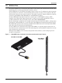
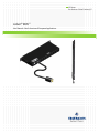
AC Power
For Business-Critical Continuity™
Liebert® MPH™
User Manual–North American & European Applications
TABLE OF CONTENTS
IMPORTANT SAFETY INSTRUCTIONS . . . . . . . . . . . . . . . . . . . . . . . . . . . . . . . . . . . . . . . . . . . . . . . .1
1.0
INTRODUCTION . . . . . . . . . . . . . . . . . . . . . . . . . . . . . . . . . . . . . . . . . . . . . . . . . . . . . . . . . .3
1.1
General Characteristics . . . . . . . . . . . . . . . . . . . . . . . . . . . . . . . . . . . . . . . . . . . . . . . . . . . . . . . 4
1.1.1
1.1.2
2.0
North American Input / Output Systems . . . . . . . . . . . . . . . . . . . . . . . . . . . . . . . . . . . . . . . . . . 4
European Input / Output Systems. . . . . . . . . . . . . . . . . . . . . . . . . . . . . . . . . . . . . . . . . . . . . . . . 4
INSTALLATION IN KNURR MIRACEL™ RACK—VERTICAL, ZERO-U MOUNT . . . . . . . . . . . . . .5
2.1
Mounting Hardware and Tools Required . . . . . . . . . . . . . . . . . . . . . . . . . . . . . . . . . . . . . . . . . 5
2.2
Install a Liebert MPH in a Knurr Miracel Rack . . . . . . . . . . . . . . . . . . . . . . . . . . . . . . . . . . . 5
2.3
Reposition Input Power Cord. . . . . . . . . . . . . . . . . . . . . . . . . . . . . . . . . . . . . . . . . . . . . . . . . . . 7
3.0
INSTALLATION IN KNURR MIRACEL RACK—HORIZONTAL RACK-MOUNT . . . . . . . . . . . . . . . .8
3.1
Mounting Hardware and Tools Required . . . . . . . . . . . . . . . . . . . . . . . . . . . . . . . . . . . . . . . . . 8
3.2
Install a Liebert MPH in a Knurr Miracel Rack . . . . . . . . . . . . . . . . . . . . . . . . . . . . . . . . . . . 8
3.2.1
3.2.2
Attach Mounting Brackets to the Liebert MPH . . . . . . . . . . . . . . . . . . . . . . . . . . . . . . . . . . . . . 8
Attach the Liebert MPH to Rack Rails . . . . . . . . . . . . . . . . . . . . . . . . . . . . . . . . . . . . . . . . . . . . 8
4.0
INSTALLING OPTIONAL ITEMS . . . . . . . . . . . . . . . . . . . . . . . . . . . . . . . . . . . . . . . . . . . . . . .9
4.1
RPC BDM—Basic Display Module . . . . . . . . . . . . . . . . . . . . . . . . . . . . . . . . . . . . . . . . . . . . . . 9
4.2
Install an Optional RPC BDM in the Rack . . . . . . . . . . . . . . . . . . . . . . . . . . . . . . . . . . . . . . . . 9
4.2.1
4.2.2
Mounting Hardware . . . . . . . . . . . . . . . . . . . . . . . . . . . . . . . . . . . . . . . . . . . . . . . . . . . . . . . . . . . 9
RPC BDM Installation on Knurr Miracel Frame . . . . . . . . . . . . . . . . . . . . . . . . . . . . . . . . . . . . 9
4.3
Temperature/Humidity Sensor Installation—Optional . . . . . . . . . . . . . . . . . . . . . . . . . . . . . 10
5.0
USING THE LIEBERT MPH . . . . . . . . . . . . . . . . . . . . . . . . . . . . . . . . . . . . . . . . . . . . . . . . 12
6.0
SPECIFICATIONS . . . . . . . . . . . . . . . . . . . . . . . . . . . . . . . . . . . . . . . . . . . . . . . . . . . . . . . .13
6.1
Agency Approvals . . . . . . . . . . . . . . . . . . . . . . . . . . . . . . . . . . . . . . . . . . . . . . . . . . . . . . . . . . . 15
6.2
Product Warranty Registration . . . . . . . . . . . . . . . . . . . . . . . . . . . . . . . . . . . . . . . . . . . . . . . . 15
FIGURES
Figure 1
Figure 2
Figure 3
Figure 4
Figure 5
Figure 6
Figure 7
Figure 8
Figure 9
Figure 10
Figure 11
Figure 12
Liebert MPH units—horizontal, 1U rack-mount and vertical, zero U mount. . . . . . . . . . . . . . . . . 3
Attach brackets to the Liebert MPH . . . . . . . . . . . . . . . . . . . . . . . . . . . . . . . . . . . . . . . . . . . . . . . . . 5
Inserting a spring nut into a T-slot . . . . . . . . . . . . . . . . . . . . . . . . . . . . . . . . . . . . . . . . . . . . . . . . . . 6
Attaching a Liebert MPH to a Knurr Miracel horizontal frame member . . . . . . . . . . . . . . . . . . . . 6
Reposition input power cord . . . . . . . . . . . . . . . . . . . . . . . . . . . . . . . . . . . . . . . . . . . . . . . . . . . . . . . . 7
Liebert MPH ready for installation in a rack—horizontal-mount . . . . . . . . . . . . . . . . . . . . . . . . . . 8
Rack-mounting the Liebert MPH. . . . . . . . . . . . . . . . . . . . . . . . . . . . . . . . . . . . . . . . . . . . . . . . . . . . 8
RPC BDM . . . . . . . . . . . . . . . . . . . . . . . . . . . . . . . . . . . . . . . . . . . . . . . . . . . . . . . . . . . . . . . . . . . . . . 9
RPC BDM installation in rack . . . . . . . . . . . . . . . . . . . . . . . . . . . . . . . . . . . . . . . . . . . . . . . . . . . . . 10
RPC BDM cable connection port on Liebert RPC . . . . . . . . . . . . . . . . . . . . . . . . . . . . . . . . . . . . . . 10
Temperature/humidity sensor mounting. . . . . . . . . . . . . . . . . . . . . . . . . . . . . . . . . . . . . . . . . . . . . 11
Model number nomenclature . . . . . . . . . . . . . . . . . . . . . . . . . . . . . . . . . . . . . . . . . . . . . . . . . . . . . . 14
TABLES
Table 1
Table 2
Liebert MPH—Model numbers and specifications . . . . . . . . . . . . . . . . . . . . . . . . . . . . . . . . . . . . . 13
Liebert MPH dimensions . . . . . . . . . . . . . . . . . . . . . . . . . . . . . . . . . . . . . . . . . . . . . . . . . . . . . . . . . 14
i
ii
IMPORTANT SAFETY INSTRUCTIONS
SAVE THESE INSTRUCTIONS
This manual contains important safety instructions. Read all safety, installation and operating
instructions before installing Liebert MPH power distribution units. Adhere to all warnings on the
unit and in this manual. Follow all operating and user instructions. Individuals without previous
training can install and operate this equipment.
• The Liebert MPH is designed for data processing equipment. The Liebert MPH is not intended for
use with life support or other designated critical devices. If uncertain about its application, consult your local dealer or Emerson representative.
• Maximum load must not exceed that shown on the Liebert MPH rating label.
• Operate the Liebert MPH in an indoor environment only in an ambient temperature range of
32°F to +131°F (0°C to +55°C). Install it in a clean environment, free of conductive contaminants,
moisture, flammable liquids, gases and corrosive substances.
• Liebert MPH power distribution units have no user-serviceable parts. Under no circumstances
attempt to gain internal access due to the risk of electric shock or burn.
• Do not continue to use the Liebert MPH if the LED panel or monitoring interface indicators are
not in accordance with these operating instructions. Refer all faults to your local dealer, Emerson
representative or Emerson Network Power Applications Engineering.
• Never block or insert any object into the Liebert MPH.
• DO NOT CONNECT equipment that could overload the Liebert MPH.
• Refer to 6.0 - Specifications to determine the electrical ratings and specifications of your Liebert
MPH. It is imperative that the power supply and connections match the specifications of the unit
being installed.
!
WARNING
Opening or removing the cover of a Liebert MPH may expose you to lethal voltages within the
power distribution unit.
Observe all cautions and warnings in this manual. Failure to do so may result in serious
injury or death.
Liebert MPH units contain no user-serviceable parts. For service, contact Emerson Network
Power Applications Engineering or your local Emerson representative. Do not attempt to
service this product yourself.
Never work alone.
!
!
CAUTION
Connecting your Liebert MPH and rack equipment to a power supply with an incorrect rating
in voltage, amperes or phase may damage the connected equipment and your Liebert MPH.
If you have questions about the power supply connections, contact Emerson Network Power
Applications Engineering or your local Emerson representative.
CAUTION
Shut down and unplug all equipment in your rack enclosure before beginning to connect
equipment to your Liebert MPH.
When connecting the rack equipment to the Liebert MPH’s receptacles, arrange cables and
connections to avoid tangling and crisscrossing the power cables. For power management
purposes, record the receptacle where each piece of equipment is connected. Receptacles on
the Liebert MPH have a numerical designation. The Liebert MPH with more than one circuit
has the outlets named with numbers and are grouped by branch with a number referring to
the proper circuit breaker.
When connecting power to the Liebert MPH’s receptacles, follow generally accepted
procedures, such as routing the power cables separately from low-voltage communication and
control wires to prevent electromagnetic interference.
1
!
CAUTION
All configuration steps must be completed before attempting to start equipment connected to
the Liebert MPH.
Notice to European Union Customers: Disposal of Old Appliances
This product uses components that are dangerous for the environment, such as electronic cards and
other electronic components. Any component that is removed must be taken to specialized collection
and disposal centers. If this unit must be dismantled, this must be done by a specialized center for collection and disposal of electric and electronics appliances or other dangerous substances.
This product has been supplied from an environmentally aware manufacturer that complies with the Waste Electrical and Electronic Equipment
(WEEE) Directive 2002/96/CE.
The “crossed-out wheelie bin” symbol at right is placed on this product to
encourage you to recycle wherever possible. Please be environmentally
responsible and recycle this product through your recycling facility at its end
of life. Do not dispose of this product as unsorted municipal waste. Follow
local municipal waste ordinances for proper disposal provisions to reduce the
environmental impact of waste electrical and electronic equipment (WEEE).
For information regarding the scrapping of this equipment, please browse
http://www.eu.emersonnetworkpower.com (“Products session” or “Contact us” session) or call our worldwide technical support at:
• 00 80011554499 (toll free number)
• +39 0298250222 (toll number based in Italy)
ROHS Compliance
The Liebert MPH modules comply with the Restriction of Hazardous Substances Directive (ROHS),
prohibiting use of six hazardous materials manufacturing of electronics, including lead-free solder.
FCC Compliance
This unit complies with the limits for a Class A device pursuant to Part 15 of the FCC Rules. Operation is subject to the following two conditions:
• This device may not cause harmful interference, and
• This device must accept any interference received, including interference that may cause undesired operation.
NOTE
This equipment has been tested and found to comply with the limits for a Class A digital
device, pursuant to part 15 of the FCC Rules. These limits are designed to provide reasonable
protection against harmful interference when the equipment is operated in a commercial
environment. This equipment generates, uses and can radiate radio frequency energy and, if
not installed and used in accordance with the instruction manual, may cause harmful
interference to radio communications. Operation of this equipment in a residential area is
likely to cause harmful interference that the user must correct, including the expense of all
corrective modifications.
2
Introduction
1.0
INTRODUCTION
The Liebert MPH Series is a managed, single-phase or three-phase power distribution unit that offers
monitoring only or monitoring along with receptacle control.
Liebert MPH units are available for mounting in either vertical, zero-U configuration and rack-mounting in standard, 19" enclosures. Vertical-mount units may have as many as 27 receptacles. The horizontal-mount units have up to nine receptacles. The output receptacles support equipment requiring
connection with NEMA 5-20R, IEC60320-C13 and IEC60320-C19 plugs.
A Liebert MPH with single-phase input has a capacity up to 7.4kW (230VAC; 32A) or 3.6kW
(120VAC; 30A). Three-phase input systems have a capacity up to 22.1kW (230/400VAC; 32A) or
10.7kW (120/208VAC; 30A). For further details, refer to 6.0 - Specifications.
Remote monitoring is enabled by the included communication card, the Liebert RPC™, which permits
managing the Liebert MPH over a secure Web page and SNMP-based network management system.
The Liebert RPC permits interconnecting multiple Liebert MPH units and connecting Liebert MPH
with other units for monitoring and management.
A Liebert MPH can be monitored locally with an RPC BDM™, an optional display module that connects directly to the communication card. The monitoring unit can be handheld, mounted in or on the
rack or mounted on a nearby wall.
Multiple Liebert MPHs can be centrally managed with Liebert Nform™, which adds group-based
receptacle management.
Figure 1
Liebert MPH units—horizontal, 1U rack-mount and vertical, zero U mount
Rack-Mount Liebert MPH
Vertical-Mount
Liebert MPH
3
Introduction
1.1
General Characteristics
•
•
•
•
•
•
•
Input current 16 to 32A
Single-phase and three-phase power input
Input voltages 120VAC, 120/208VAC, 208VAC, 230VAC, 230/400VAC, 240VAC
Line-to-Line and Line-to-Neutral
Output Receptacles: NEMA and IEC
Input connection by hard-wired cords, 10 feet (3m) long
Input power cord plugs: L5-20P, L5-30P, L6-20P, L6-30P, L21-30P, IEC-C20, IEC309 3-wire 32A,
IEC309 5-wire 32A
For details, refer to 6.0 - Specifications. Refer to Table 2 for the dimensions.
1.1.1
North American Input / Output Systems
120VAC, Single-Phase Input - Vertical-Mount
L5-20P or L5-30P plug connection, 10 ft. (3m) input power cord, 20 or 30A; 5-20R (T-blade) receptacles, 27 outlets; 68.25 in. (1735mm) long
120VAC, Single-Phase Input / Output - Rack-Mount
L5-20P or L5-30P plug connection, 10 ft. (3m) input power cord, 20 or 30A; 5-20R (T-blade) receptacles, 9 outlets; 1U tall
200-240VAC, Single-Phase Input / Output - Vertical-Mount
L6-20P or L6-30P plug connection, 10 ft. (3m) input power cord, 20 or 30A, 27 IEC-C13 or 21 IEC-C13
plus 6 IEC-C19; 68.25 in (1735mm) long
200-240VAC, Single-Phase Input / Output - Rack-Mount
L6-20P or L6-30P plug connection, 10 ft. (3m) input power cord, 20 or 30A; IEC-C13 receptacles, 9
outlets; 1U tall
120/208VAC, Three-Phase Input / 208 & 120VAC Output - Vertical-Mount
L21-30P or L15-30P plug connection, 10 ft. (3m) input power cord, 20 or 30A; 27 IEC-C13 or
21 IEC-C13 plus 6 IEC-C19 or 21 IEC-C13 plus 6 5-20R receptacles, 27 outlets; 68.25 in. (1735mm)
long
1.1.2
European Input / Output Systems
230VAC, Single-Phase Input / Output - Vertical-Mount
IEC-C20 or IEC-309 plug connection, 3m (10 ft.) input power cord, 16 or 32A, 27 IEC-C13 or
21 IEC-C13 plus 6 IEC-C19; 68.25 in (1735mm) long
230VAC, Single-Phase Input / Output - Rack-Mount
IEC-C20 or IEC-309 plug connection, 3m (10 ft.) input power cord, 16 or 32A; IEC-C13 receptacles,
9-outlets; 1U tall
400VAC, Three-Phase Input / 230VAC Output - Vertical-Mount
IEC-309 plug connection, 3m (10 ft.) input power cord, 20 or 30A; 27 IEC-C13 or 21 IEC-C13 plus 6
IEC-C19 receptacles, 27 outlets; 1735mm (68.25 in.) long
4
Installation in Knurr Miracel™ Rack—Vertical, Zero-U Mount
2.0
INSTALLATION IN KNURR MIRACEL™ RACK—VERTICAL, ZERO-U MOUNT
A Liebert MPH can be installed in a Knurr Miracel rack on the frame members using field-supplied
Knurr hardware. The unit can be installed on the face or the side of frame members.
2.1
Mounting Hardware and Tools Required
Factory-Supplied
• Brackets: 2
• Screws, 6-32 x 1/4": 8
Field-Supplied
• Spring-nuts, supplied with Knurr rack
• Tool-less fasteners, supplied with Knurr rack
• Phillips screwdriver
2.2
Install a Liebert MPH in a Knurr Miracel Rack
Determine where in the Knurr Miracel the Liebert MPH will be installed and follow the applicable
instructions below. Installation requires attaching two brackets to the Liebert MPH, inserting four
spring nuts into the rack and using the brackets to attach the Liebert MPH to the rack. Refer to
Figures 2, 3 and 4. (Refer to Table 2 for the dimensions of the Liebert MPH.)
The bracket is intended for attaching the Liebert MPH to the face of a frame member.
1. Use four of the 6-32 screws to attach a bracket to each end of the Liebert MPH. The supplied
brackets have four holes that match holes on each end of the Liebert MPH.
• If mounting on horizontal frame members, attach the brackets in-line, as shown in the left side of
Figure 2.
• If mounting on an upright frame member, attach the brackets at a right angle to the Liebert MPH
as shown in the right side of Figure 2.
2. Tighten the screws firmly.
3. Insert two spring nuts into the appropriate T-slot on the frame member.
Position the spring nuts to accommodate screws inserted through slots in the brackets. To move
the spring nuts, press down on each with a small, pointed object and slide each into position.
4. Hold the Liebert MPH in place and attach the top of the unit to the rack with tool-less fasteners.
5. Tighten the screws firmly.
6. Repeat Steps 3 through 5 for the lower bracket on the lower end of the Liebert MPH.
Figure 2
Attach brackets to the Liebert MPH
In-Line Bracket
Attachment on Liebert MPH
(used for mounting on horizontal
frame members)
90-Degree Bracket
Attachment on Liebert MPH
(used for mounting on an upright
frame member)
5
Installation in Knurr Miracel™ Rack—Vertical, Zero-U Mount
Figure 3
Inserting a spring nut into a T-slot
T-slot
Spring nut inserted into
T-slot; leaf spring goes
inside
Figure 4
Attaching a Liebert MPH to a Knurr Miracel horizontal frame member
Tool-less fasteners
supplied with Knurr rack
6
Installation in Knurr Miracel™ Rack—Vertical, Zero-U Mount
2.3
Reposition Input Power Cord
The Liebert MPH is shipped from the factory with the input power cord entering from the end of the
unit. The cord can be repositioned if it will need to enter from the front. To reposition the cord:
1. Remove the four screws retaining the input power plate.
2. Reposition so that power cord enters from front.
3. Reinstall the screws and tighten them.
Figure 5
Reposition input power cord
Input Power
Plate Screws
Input Power Plate
Repositioned for Different
Cable Angle
7
Installation in Knurr Miracel Rack—Horizontal Rack-Mount
3.0
INSTALLATION IN KNURR MIRACEL RACK—HORIZONTAL RACK-MOUNT
A Liebert MPH can be installed in a Knurr Miracel rack in only 1U of equipment space using fieldsupplied Knurr hardware.
3.1
Mounting Hardware and Tools Required
Factory-Supplied
• L-shaped bracket: 2
• Screws, 6-32 x 1/4": 8
Field-Supplied
• Phillips screwdriver
3.2
Install a Liebert MPH in a Knurr Miracel Rack
3.2.1
Attach Mounting Brackets to the Liebert MPH
Before attaching the horizontal-mount brackets to the Liebert MPH, determine whether to attach the
brackets to the front edge or rear edge of the unit. This will depend, in part, on whether the Liebert
MPH would be best placed in the front of the rack or in the rear for routing power and communication
wires. Bracket location also determines whether the Liebert MPH display is viewed from the front or
rear of the rack.
When mounting the Liebert MPH, position the unit for ease of access and clearance. (Refer to Table 2
for the dimensions of the Liebert MPH.)
To attach the brackets:
1. Hold one mounting bracket against the side of the Liebert MPH, making sure that the end of the
bracket with the round holes is against the unit.
2. Attach the bracket to the unit with four Phillips head screws, tightening them firmly.
3. Repeat Steps 1 and 2 for the bracket on the opposite side of the Liebert MPH.
Figure 6
Liebert MPH ready for installation in a rack—horizontal-mount
Front mounting
holes
Slots will attach
to rack-mount rail
3.2.2
Attach the Liebert MPH to Rack Rails
Determine where the Liebert MPH would be best placed in the rack for routing power and communication wires.
The rack-mount Liebert MPH is installed horizontally in standard rack face position on the rails
using the square, EIA-spaced holes. They use four captive nuts snapped into the rail holes and four
screws to attach the Liebert MPH brackets to the rail.
As with all Liebert rack-mount equipment, obtain the appropriate size rack-mounting hardware kit
for captive nuts and screws.
Figure 7
Rack-mounting the Liebert MPH
Screws go through bracket holes,
through rail and insert into the
captive nuts
8
Installing Optional Items
4.0
INSTALLING OPTIONAL ITEMS
4.1
RPC BDM—Basic Display Module
The RPC BDM provides local display of electrical status for all connected Liebert MPH systems. Display information is accessed via a navigation switch on the RPC BDM. The RPC BDM is cable-connected to the Liebert RPC allowing the user to locate the display to suit the local reading
requirements. A 2-meter cable and general mounting provisions are provided. A single display can be
used for up to four Liebert MPH connected in a Rack PDU Array™.
Figure 8
4.2
RPC BDM
Install an Optional RPC BDM in the Rack
The RPC BDM (Basic Display Module) can be mounted in the rack with either the included hardware
or with a cable tie through the slot on the back of the module (see Figure 9). Either method permits
moving the RPC BDM to a different place in the same rack or to another rack.
4.2.1
Mounting Hardware
•
•
•
•
Spring nut M5: 1
Spacer sleeve: 1
Special MPH screw: 1
Cable clip: 1
Tools Required
• Flat-blade screwdriver
4.2.2
RPC BDM Installation on Knurr Miracel Frame
1. Determine the mounting location in the rack.
2. Insert a spring nut into a T-slot on the frame member where the RPC BDM will be installed (refer
to Figure 3).
3. Insert the Liebert MPH screw into the spacer sleeve.
4. Insert the Liebert MPH screw into the spring nut and tighten securely with the screwdriver.
5. Hang the RPC BDM on the Liebert screw with the hooded mounting slot on the back of the RPC
BDM (see Figure 9).
6. Connect the RPC BDM to the Liebert RPC with an Ethernet cable.
Be certain to connect the cable to the correct port on the Liebert RPC (see Figure 10).
9
Installing Optional Items
Figure 9
RPC BDM installation in rack
Cable tie fits in small
slot on RPC BDM,
loops around cabinet
member
Head of the Liebert MPH Screw
in frame fits into hooded slot
on back of RPC BDM
Figure 10 RPC BDM cable connection port on Liebert RPC
RPC BDM cable
connection port
on Liebert RPC
4.3
Temperature/Humidity Sensor Installation—Optional
Optional Liebert SN temperature/humidity sensors are available to assist in monitoring conditions in
the rack. Liebert SN sensors are designed for installation in a Knurr Miracel without tools, but each
may be placed in any area to monitor temperature and humidity levels. Each connects to the Liebert
RPC, which makes readings available to Liebert monitoring methods.
Only one mounting method is addressed in this manual: attaching a single sensor with a bracket to a
Knurr Miracel frame member. For details on other mounting locations and methods, refer to the Liebert SN quick-start guide, SL-20840, or to the Liebert RPC user manual, SL-20825. Each is available
at Liebert’s Web site, www.liebert.com
10
Installing Optional Items
To install a sensor on a Knurr Miracel frame member:
1. Assemble the Liebert SN and sensor bracket:
a. Insert the sensor bracket base into one end of the sensor support as shown in Figure 11.
b. Snap the sensor into the other end of the sensor support.
2. Choose where in the rack to install the sensor assembly. Emerson recommends placing the sensor
in the area that is likely to be warmest.
3. Hold the sensor bracket on a T-slot on the Knurr Miracel frame where the sensor will be placed.
4. Insert the included quarter-turn fastener through the rectangular hole in the sensor bracket base
and into the T-slot (see Figure 11).
5. Turn the fastener clockwise 90 degrees, a quarter of a turn.
6. Route the sensor cable to the Liebert RPC and insert it into the card’s external sensor port.
For further details, refer to the Liebert RPC user manual, SL-20825, which shipped with the card
and is available at Liebert’s Web site: www.liebert.com
Figure 11
Temperature/humidity sensor mounting
Sensor Support
Sensor Bracket Base
Liebert SN Sensor
snapped into support
Quarter-Turn Fastener
Rectangular protrusion passes
through bracket slot (above) and
into T-slot on Knurr Miracel frame
member (below).
Liebert SN
Sensor Cable
11
Using the Liebert MPH
5.0
USING THE LIEBERT MPH
The Liebert MPH is ready for service after it has been installed in the rack and equipment has been
connected to the output sockets. Refer to the Liebert RPC user manual, SL-20825, available at the
Liebert Web site, for full details on controlling and monitoring the Liebert MPH: www.liebert.com
Emerson recommends following these steps when starting a newly installed Liebert MPH:
1. Shut down and unplug all equipment in the rack from input power sources.
2. If the Liebert MPH will be monitored over a network, connect an Ethernet cable to the network
port on the factory-installed Liebert RPC (for details, refer to the Liebert RPC manual, SL-20825,
available at the Liebert Web site: www.liebert.com).
3. Connect input power to the Liebert MPH.
4. Route the rack equipment’s power cables to the Liebert MPH, following proper procedures and
good practices, such as segregating power cables from control cables and keeping cable bends to
recommended angles.
5. Connect the rack equipment’s input power cables to the Liebert MPH, recording where each piece
of rack equipment is connected, using the receptacle numbers on the Liebert MPH.
6. Post the connection information on or near the rack and at any remote monitoring location
7. Switch On the connected rack equipment one piece at a time and verify that each is operating
properly.
8. Monitor and control the Liebert MPH as detailed in the Liebert RPC manual, SL-20825, available
at the Liebert Web site: www.liebert.com
12
Specifications
6.0
Table 1
SPECIFICATIONS
Liebert MPH—Model numbers and specifications
Input
Part Number
Output
Max.
Rated Continuous
Voltage Amps
Amps
kW Phase
Plug
Receptacle/Socket
Configuration
Form
Factor
Monitoring Level - Basic
North American Applications
MPH-NBV27NXXH30
208/120
30
24
8.6
3
NEMA L21-30
(27) IEC-C13
Vertical
MPH-NBV27NXXF30
208-240
30
24
4.9
1
NEMA L6-30
(27) IEC-C13
Vertical
MPH-NBV27NXXE30
208-240
20
16
3.3
1
NEMA L6-20
(27) IEC-C13
Vertical
MPH-NBV27NOXH30 208/120
30
24
8.6
3
NEMA L21-30
(21) IEC-C13 & (6) IEC-C19
Vertical
MPH-NBV27NOXF30
208-240
30
24
4.9
1
NEMA L6-30
(21) IEC-C13 & (6) IEC-C19
Vertical
MPH-NBV27AXXH30
208/120
30
24
8.6
3
NEMA L21-30
(27) NEMA 5-20R T-Slot
Vertical
MPH-NBV27AXXD30
120
30
24
2.8
1
NEMA L5-30
(27) NEMA 5-20R T-Slot
Vertical
MPH-NBV27AXXC30
120
20
16
1.9
1
NEMA L5-20
(27) NEMA 5-20R T-Slot
MPH-NBV27ANXH30
208/120
30
24
8.6
3
NEMA L21-30 (21) IEC-C13 & (6) NEMA 5-20R T-Slot
Vertical
Vertical
MPH-NBR09NXXF30
208-240
30
24
4.9
1
NEMA L6-30
(9) IEC-C13
Rack mount
MPH-NBR09NXXE30
208-240
20
16
3.3
1
NEMA L6-20
(9) IEC-C13
Rack mount
MPH-NBR09AXXD30
120
30
24
2.8
1
NEMA L5-30
(9) NEMA 5-20R T-Slot
Rack mount
MPH-NBR09AXXC30
120
20
16
1.9
1
NEMA L5-20
(9) NEMA 5-20R T-Slot
Rack mount
European Applications
MPH-EBV27NXXR30
400/230
32
32
12.8
3
IEC-309
(27) IEC-C13
Vertical
MPH-EBV27NXXQ30
230
32
32
7.3
1
IEC-309
(27) IEC-C13
Vertical
MPH-EBV27NXXO30
230
16
16
3.6
1
IEC-C20
(27) IEC-C13
Vertical
MPH-EBV27NOXR30
400/230
32
32
12.8
3
IEC-309
(21) C-13 & (6) C-19
Vertical
MPH-EBV27NOXQ30
230
32
32
7.3
1
IEC-309
(21) C-13 & (6) C-19
Vertical
MPH-EBV27NOXO30
230
16
16
3.6
1
IEC-C20
(21) C-13 & (6) C-19
Vertical
MPH-EBR09NXXQ30
230
32
32
7.3
1
IEC-309
(9) IEC-C13
Rack mount
MPH-EBR09NXXO30
230
16
16
3.6
1
IEC-C20
(9) IEC-C13
Rack mount
Monitoring Level - Controlled
North American Applications
MPH-NCV27NXXH30
208/120
30
24
8.6
3
NEMA L21-30
(27) IEC-C13
Vertical
MPH-NCV27NXXF30
208-240
30
24
4.9
1
NEMA L6-30
(27) IEC-C13
Vertical
MPH-NCV27NXXE30
208-240
20
16
3.3
1
NEMA L6-20
(27) IEC-C13
Vertical
MPH-NCV27NOXH30 208/120
30
24
8.6
3
NEMA L21-30
(21) IEC-C13 & (6) IEC-C19
Vertical
MPH-NCV27NOXF30
208-240
30
24
4.9
1
NEMA L6-30
(21) IEC-C13 & (6) IEC-C19
Vertical
MPH-NCV27AXXH30
208/120
30
24
8.6
3
NEMA L21-30
(27) NEMA 5-20R T-Slot
Vertical
MPH-NCV27AXXD30
120
30
24
2.8
1
NEMA L5-30
(27) NEMA 5-20R T-Slot
Vertical
MPH-NCV27AXXC30
120
20
16
1.9
1
NEMA L5-20
(27) NEMA 5-20R T-Slot
MPH-NCV27ANXH30
208/120
30
24
8.6
3
NEMA L21-30 (21) IEC-C13 & (6) NEMA 5-20R T-Slot
Vertical
Vertical
MPH-NCR09NXXF30
208-240
30
24
4.9
1
NEMA L6-30
(9) IEC-C13
Rack mount
MPH-NCR09NXXE30
208-240
20
16
3.3
1
NEMA L6-20
(9) IEC-C13
Rack mount
MPH-NCR09AXXD30
120
30
24
2.8
1
NEMA L5-30
(9) NEMA 5-20R T-Slot
Rack mount
MPH-NCR09AXXC30
120
20
16
1.9
1
NEMA L5-20
(9) NEMA 5-20R T-Slot
Rack mount
MPH-ECV27NXXR30
400/230
32
32
12.8
3
IEC-309
(27) IEC-C13
Vertical
MPH-ECV27NXXQ30
230
32
32
7.3
1
IEC-309
(27) IEC-C13
Vertical
MPH-ECV27NXXO30
230
16
16
3.6
1
IEC-C20
(27) IEC-C13
Vertical
MPH-ECV27NOXR30 400/230
32
32
12.8
3
IEC-309
(21) C-13 & (6) C-19
Vertical
MPH-ECV27NOXQ30
230
32
32
7.3
1
IEC-309
(21) C-13 & (6) C-19
Vertical
MPH-ECV27NOXO30
230
16
16
3.6
1
IEC-C20
(21) C-13 & (6) C-19
Vertical
MPH-ECR09NXXQ30
230
32
32
7.3
1
IEC-309
(9) IEC-C13
Rack mount
MPH-ECR09NXXO30
230
16
16
3.6
1
IEC-C20
(9) IEC-C13
Rack mount
European Applications
13
Specifications
Table 2
Liebert MPH dimensions
Vertical-Mount
W x D x H, in. (mm)
Rack-Mount
W x D x H, in. (mm)
1.97 x 3.13 x 68.1
(50 x 80 x 1730)
17.25 x 7.0 x 1.73
(438 x 178 x 44 mm)
Figure 12 Model number nomenclature
MPHMODEL - MPH
N
C
R
TYPE
B = Basic, Monitor
Only
C = Controlled
Outlets
REGION
N = North America
E = Europe
09
AX
NUMBER OF
RECEPTACLES
09 = 9 Receptacles
27 = 27 Receptacles
MOUNTING
V = Vertical Mounting
(Zero U)
R = Rack (Horizontal)
Mounting
EXAMPLE:
MPH-NCR09AXC30:
Liebert MPH
Controlled Outlets
Rack Mounting
9 Receptacles
5-20R 00 Receptacle Type (no second set of receptacles)
—
L5-20P Plug
3m Input Power Cord
14
X
UNASSIGNED
RECEPTACLE TYPE
(Two Sets Possible)
A = 5-20R 00
N = IEC-C13
O = IEC-C19
C
30
INPUT CORD
LENGTH
(two digits)
INPUT PLUG TYPE
C = L5-20P
D = L5-30P
E = L6-20P
F = L6-30P
H = L21-30P
J = L15-30
K to M = TBD
O = IEC-C20
Q = IEC-309 32A 3W
R = IEC-309 32A 5W
Specifications
6.1
Agency Approvals
120V and 208V Single-Phase and Three-Phase Units
•
•
•
•
•
UL 60950-1 Information Technology Equipment
CAN/CSA-C22.2 No. 60950-1-03 Information Technology Equipment
FCC, Title 47, Part 15 Subpart B for Class B operation as defined by ANSI Standard C63.4
ROHS Compliant
ISTA Procedure 1A and 2A
230V and 400V Three-Phase Units
•
•
•
•
CE Markings Directive 93/68EEC according to the Low-Voltage Directive (LVD)
CE Markings Directive 73/23/EEC
Electromagnetic Compatibility (EMC) Directive 89/336/EEC
European Directive 2002/95/EC on the restriction of the use of certain hazardous substances in
electrical and electronic equipment (ROHS and WEEE Compliant)
• IEC 61709
• ISTA Procedure 1 A and 2A
6.2
Product Warranty Registration
To register for warranty protection, visit the Service and Support section of the Liebert Web site at:
www.liebert.com
Click on Product Registration and fill out the form.
15
Specifications
NOTES
16
Specifications
17
Specifications
18
Ensuring The High Availability
Of Mission-Critical Data And Applications.
Emerson Network Power, the global leader in enabling business-critical
continuity, ensures network resiliency and adaptability through
a family of technologies—including Liebert power and cooling
technologies—that protect and support business-critical systems.
Liebert solutions employ an adaptive architecture that responds
to changes in criticality, density and capacity. Enterprises benefit
from greater IT system availability, operational flexibility and
reduced capital equipment and operating costs.
Technical Support / Service
Web Site
www.liebert.com
Monitoring
[email protected]
800-222-5877
Outside North America: +00800 1155 4499
Single-Phase UPS & Server Cabinets
[email protected]
800-222-5877
Outside North America: +00800 1155 4499
Three-Phase UPS & Power Systems
800-543-2378
Outside North America: 614-841-6598
Environmental Systems
800-543-2778
Outside the United States: 614-888-0246
Locations
United States
1050 Dearborn Drive
P.O. Box 29186
Columbus, OH 43229
Europe
Via Leonardo Da Vinci 8
Zona Industriale Tognana
35028 Piove Di Sacco (PD) Italy
+39 049 9719 111
Fax: +39 049 5841 257
Asia
29/F, The Orient Square Building
F. Ortigas Jr. Road, Ortigas Center
Pasig City 1605
Philippines
+63 2 687 6615
Fax: +63 2 730 9572
While every precaution has been taken to ensure the accuracy
and completeness of this literature, Liebert Corporation assumes no
responsibility and disclaims all liability for damages resulting from use of
this information or for any errors or omissions.
© 2009 Liebert Corporation
All rights reserved throughout the world. Specifications subject to change
without notice.
® Liebert is a registered trademark of Liebert Corporation.
All names referred to are trademarks
or registered trademarks of their respective owners.
SL-20827_REV01_08-09
Emerson Network Power.
The global leader in enabling Business-Critical Continuity.
AC Power
Embedded Computing
Embedded Power
Connectivity
DC Power
Monitoring
EmersonNetworkPower.com
Outside Plant
Power Switching & Controls
Racks & Integrated Cabinets
Services
Precision Cooling
Surge Protection
Business-Critical Continuity, Emerson Network Power and the Emerson Network Power logo are trademarks and service marks of Emerson Electric Co.
©2009 Emerson Electric Co.