1
TH-2050-VFM
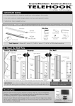
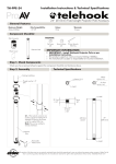
Step 7. Cable Management
Installation Instructions
70
Connect cables to your Display and
route through Cable Clips.
,iÛiÊ
>LiÊ
ÛiÀÃÊÕÃ}Ê>Ê*
«ÃÊi>`Ê-VÀiÜ`ÀÛiÀ]Ê>`ÊÀÕÌi
the cables along the length of the arms. Reattach the Cable Covers
to hold the Cables in place.
Cable Covers
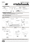
Flat Screen Wall Mount | Full Motion
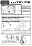
Component Checklist
Hardware
Articulated Arm
VESA plate
Cable Covers
Concrete
Anchor (x3)
4mm
Allen Key
M4 Washer (x4)
M5 Washer (x4)
Coach Washer
M8 (x3)
Drilling
Guide
TIP: Leave enough slack in the cables
to allow full movement at the joints.
Cable Clips
Coach
Bolt M8 (x3)
M4/5 Spacer Bush (x4)
M8 Dome Nut (x4)
M6/8 Spacer Bush (x4)
Star Washer (x4)
Step 8. Tilt Adjustment
,ii>ÃiÊÌ
iÊ
>«ÊiÛiÀÊ>`ÊÌÌÊÌ
i
Display up or down as desired.
/}
ÌiÊÌ
iÊ
>«ÊiÛiÀÊÌÊV
the Display in desired position.
TILT DOWN
LOOSEN
Clamp
iÛiÀ
PULL
ÝÌiÃÊ*>ÌiÊÊÝÓ®
ÝÌiÃÊ*>ÌiÊÊÝÓ®
TOOLS REQUIRED:
ÊUÊ*ÜiÀÊÀ
ÊUÊ*
«ÃÊi>`Ê-VÀiÜ`ÀÛiÀ
ÊUÊ-«ÀÌÊiÛi
ÊUÊxÊ3/16”) Drill Bit
ÊUÊ£äÊ3/8”) Masonry Drill Bit
ÊUÊ£ÎÊ1/2”) Socket Wrench or Shifter
ÊUÊ£{Ê9/16”) Socket Wrench or Shifter
Mounting Screws
M8x16mm / M8x45mm (x4 each)
M6x16mm / M6x30mm (x4 each)
M5x16mm / M5x25mm (x4 each)
M4x16mm / M4x25mm (x4 each)
IMPORTANT INFORMATION
TIGHTEN
TILT UP
TIP: If the Clamp Lever is obstructed
pull it outwards to disengage the
rachet mechanism.
! IMPORTANT - Install Telehook Wall Mount as per Installation Instructions.
! Telehook Wall Mount supports Displays weighing up to 35kg (77lbs), with VESA hole configurations:
ÊÊÊÊUÊ100x100mm (4”x4”)
UÊ300x200mm (12”x8”)
UÊ200x100mm (8”x4”)
UÊ300x300mm (12“x12”)
UÊ200x200mm (8”x8”)
UÊ400x400mm (16”x16”) - using the extensions plates supplied.
! The Manufacturer accepts no responsibility for incorrect installation.
Step 1. Check Components
Installation Complete
Your Telehook Wall Mount Articulated Arm installation is complete and ready for use.
As TFT Manufacturers are constantly releasing new monitor models, Atdec does not accept responsibility if the VESA mounting does not comply with the international standards.
Due to continuing product development, the manufacturer reserves the right to alter specifications without notice. *ÕLÃ
i`\ 11.11.09 ©
Check you have received all parts against the Component Checklist and Hardware above.
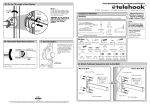
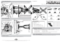
Step 5. Attaching the VESA Plate to your Display
Step 2. Locate Drilling Position
Choose the location of your Telehook Wall Mount, ensuring that the wall is structurally sound (for a timber stud wall,
locate the stud using a stud detection device). Use the Drilling Guide to mark out the hole centres.
Peel away the
backing from the
double-sided
adhesive tape.
Un-fold the Drilling
Guide and open the
Dust Collector.
Top
Drilling Guide
FRONT
Choose appropriate Mouting Screws and Washers
from the Hardware supplied to suit your Display.
WALL
Mounting Screws (x4)
Recessed Mounting Holes or
Display with a Curved Rear Panel
Washers (x4)
Drilling Guide
BACK
Dust Collector
Double-sided
tape (x2)
If the Mounting Holes are recessed
into the back of the Display, or the
Display has a curved rear panel, use
the appropriate Spacer Bushes
supplied to pack the Mounting Holes.
NOTE: Ensure the VESA plate is
securely fixed to the display.
Mounting
Screw
Position the Drilling Guide vertically
onto the wall using a spirit level.
Washer
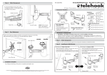
Step 3. Attaching the Articulated Arm to the Wall
Timber Stud Wall
- Using the Drilling Guide, drill three 5mm (3/16”)
diameter holes, 50mm (2”) deep.
- Secure the Mouting Plate to the wall using the Coach
Bolts and Coach Washers supplied.
Masonry Wall
- Using the Drilling Guide, drill three 10mm (3/8”)
diameter holes, 50mm (2”) deep.
- Secure the Mouting Plate to the wall using the Coach
Bolts, Coach Washers and Anchors supplied.
Timber
Stud
VESA plate
Top of
Display
Spacer
Bush
Mounting
Hole
Back of Display
IMPORTANT:
Use the 4mm Allen Key to loosen
the Security Screw until flush with
the Quick-release Hook
(do not remove).
Coach Bolt
M8 (x3)
OR
Coach Washer
M8 (x3)
Concrete
Anchor (x3)
UÊÊV>ÌiÊi>V
ÊÝÌiÃÊ*>ÌiÊÌ
the VESA Plate (see right).
UÊÊ*ÃÌÊÌ
iÊ-Ì>ÀÊ7>Ã
iÀÃÊÛiÀ
each bolt.
UÊÊ-iVÕÀiÊÌ
iÊÝÌiÃÊ*>ÌiÃÊÊ
position by tightening the Dome
Nuts firmly using a 14mm (9/16”)
Socket Wrench or Shifter.
Slide the VESA plate onto the
Quick-release Hook.
+/- 5°
VESA plate
LOOSEN
A
B
Tighten the Security
Screw fully to lock.
Dome Nut
Star Washer
Rotate the Display into a Horizontal
position as required.
Coach Washer
M8 (x3)
Step 4. Fasten Extension Plates to the VESA Plate (optional)
Only use the Extension Plates if the Display you wish to
mount has a 400x400mm VESA hole mounting configuration.
If not, skip to Step 5.
( brequired)
b
Step 6. Attaching your Display to the Articulated Arm
Masonry
Wall
Coach Bolt
M8 (x3)
Mounting
Hole
TIGHTEN
FIRMLY
400mm
(16”x16”)
VESA Plate
Security
Screw
(FLUSH)
TIGHTEN
Quick-release
Hook
VESA Plate
Extension Plate
B
A
400mm (16”x16”)
Back of Display