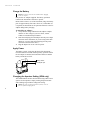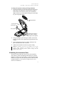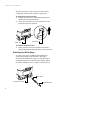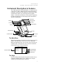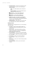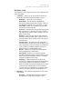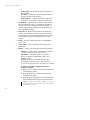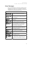
1
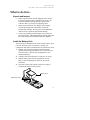
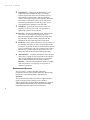
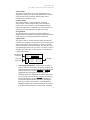
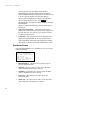
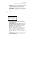
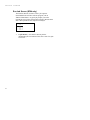
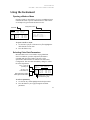
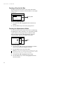
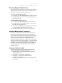
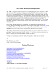
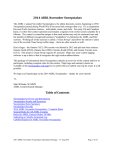
SP60 Series
S P H E R E
S P E C T R O P H O T O M E T E R
Getting Started
SP60 SERIES
SPHERE
SPECTROPHOTOMETER
The Manufacturer:
Der Hersteller:
El fabricante:
Le fabricant:
Il fabbricante:
X-Rite, Incorporated
4300 44th Street, S.E.
Grand Rapids, Michigan 49512
Declares that:
gibt bekannt daß:
advierte que:
avertit que:
avverte che:
Spectrophotometer
SP60 Series
is not intended to be connected to a public telecommunications network.
nicht an ein öffentliches Telekommunikations-Netzwerk angeschlossen werden soll.
no debe ser conectado a redes de telecomunicaciones públicas.
ne doit pas être relié à un réseau de télécommunications publique.
non deve essere connettuto a reti di telecomunicazioni pubblici.
CE DECLARATION
Manufacturer's Name:
Manufacturer's Address:
X-Rite, Incorporated
4300 44th Street, S.E.
Grand Rapids, Michigan
U.S.A.
Model Name:
Model No.:
Spectrophotometer
SP60 Series
Directive(s) Conformance:
EMC 89/336/EEC LVD 73/23/EEC
WEEE
As of August 13, 2005, X-Rite products meet the European Union – Waste
Electrical and Electronic Equipment (WEEE) directive. Please refer to
www.xrite.com for more information on X-Rite’s compliance with the WEEE
directive.
SP60 SERIES
SPHERE
SPECTROPHOTOMETER
Proprietary Notice
The information contained in this manual is derived from patent and proprietary data of
X-Rite, Incorporated. The contents of this manual are the property of X-Rite, Incorporated
and are copyrighted. Any reproduction in whole or part is strictly prohibited. Publication
of this information does not imply any rights to reproduce or use this manual for any
purpose other than installing, operating, or maintaining this instrument. No part of this
manual may be reproduced, transcribed, transmitted, stored in a retrieval system, or
translated into any language or computer language, in any form or by any means,
electronic, magnetic, mechanical, optical, manual, or otherwise, without the prior written
permission of an officer of X-Rite, Incorporated.
This instrument may be covered by one or more patents. Refer to the instrument for actual
patent numbers.
Copyright © 2007 by X-Rite, Incorporated
“ALL RIGHTS RESERVED”
X-Rite® is a registered trademark of X-Rite, Incorporated. All other logos, brand names, and
product names mentioned are the properties of their respective holders.
Federal Communications Commission Notice
This equipment has been tested and found to comply with the limits for a Class A digital device,
pursuant to Part 15 of the FCC Rules. These limits are designed to provide reasonable protection
against harmful interference when the equipment is operated in a commercial environment. This
equipment generates, uses, and can radiate radio frequency energy and, if not installed and used
in accordance with the instruction manual, may cause harmful interference to radio
communications. Operation of this equipment in a residential area is likely to cause harmful
interference in which case the user will be required to correct the interference at his own
expense.
Industry Canada Compliance Statement
This Class A digital apparatus meets all requirements of the Canadian Interference-Causing
Equipment Regulations.
Cet appareil numérique de la classe A respecte toutes les exigences du Règlement sur le matériel
brouilleur du Canada.
NOTE: Shielded interface cables must be used in order to maintain compliance with the desired
FCC and European emission requirements.
WARNING: This instrument is not for use in explosive environment.
CAUTION: Operational hazard exists if battery chargers other than X-Rite SE30-81 (115V) or
SE30-77 (100-240V) is used. Use only X-Rite battery pack SP62-79-23, other types may burst
causing personal injury.
1
GETTING
STARTED
Getting Started
This document is designed to get you familiarized with your
X-Rite SP60 Series Spectrophotometer. If you need any further
instructions or information, you can find a complete Operator's
Manual in a Portable Document Format (PDF) file on the CD
that is shipped with your instrument.
Table of Contents
What to do first…
Unpack and Inspect
Install the Battery Pack
Charge the Battery Pack
Apply Power
Changing the Aperture Setting (SP64 only)
Unlatching the Instrument Shoe
Attaching the Wrist Strap
Instrument Description & Features
The Main Menu
The Keys
Measurement Screens
Standard Screen
Projects Screen
Run Job Screen (SP64 only)
Using the Instrument
Opening a Mode or Menu
Selecting Color Data Parameters
Opening a Pop-Up Editor
Opening an Alphanumeric Editor
Selecting Single or Multiple Items
Important Measurement Techniques
Instrument Indicator Light
Taking a Measurement
Calibrating the Instrument
Calibration Procedure
Configuring the Instrument
Configuration Settings
User Dialog Error Messages
2
3
3
3
4
4
4
5
6
7
7
7
8
10
11
12
13
13
13
14
14
15
15
15
16
17
17
18
18
23
SP60 SERIES
SPHERE
SPECTROPHOTOMETER
What to do first…
Unpack and Inspect
•
Remove the instrument from the shipping carton. Be sure
to keep the original carton. If shipment is necessary, the
instrument should be packaged in the original carton.
Contact X-Rite if you need a new shipping carton.
•
Inspect the instrument for any damage. If any damage
occurred during shipment, immediately contact the
transportation company. Do not proceed with installation
until the carrier’s agent has inspected the damage.
•
Check your packaging contents against your packing list
and original order. A detailed packaging drawing and a parts
list can be found in the instrument's Operator's Manual.
Install the Battery Pack
The instrument is shipped from the factory with the battery pack
removed. The battery pack is located in a carrying case
compartment and must be installed before the instrument is used.
1. Hold the shoe next to the instrument housing and lift
upward on the spring-loaded latch (refer to Unlatching the
Instrument Shoe). Open the shoe perpendicular to the
instrument housing.
2. Carefully rotate the instrument over and rest it on its top.
3. Slide the battery pack into the compartment with the
battery connector facing down and to the back of the
instrument.
4. Press down on the pack until the connector is properly
seated and the tabs click into position.
Battery Pack
Battery Connector
3
GETTING
STARTED
Charge the Battery
NOTE: The battery pack must be installed before plugging
in the AC Adapter.
Only use the AC Adapter supplied. The battery pack must
remain in the instrument at all times to operate.
Before initial “remote” use of the instrument, charge the battery
pack for approximately four hours. However, if immediate use
is required, the instrument can be operated “tethered” to the AC
adapter during battery charging.
To attach the AC adapter:
1. Verify that the voltage indicated on the adapter complies
with the AC line voltage in your area. If not, contact
X-Rite or an authorized representative.
2. Insert the small plug from the adapter into the power-input
connector on the instrument. (If you are using serial cable
SE108-92, you may insert the small plug into the power
connector at the end of the cable.)
3. Plug the adapter into an AC wall receptacle.
Apply Power
The Battery switch—located on the back of the instrument—
turns the instrument off and on during battery operation. When
the AC adapter is attached, the instrument remains on and the
battery switch has no effect.
Battery Switch
AC Adapter Input
Changing the Aperture Setting (SP64 only)
The standard SP64 can take measurements using either a 4mm
aperture or 8mm aperture. Simply rotating the aperture knob
and switching target windows changes the setting.
NOTE: The large spot SP64 instrument (14mm) does not
have an aperture changing knob.
4
SP60 SERIES
SPHERE
SPECTROPHOTOMETER
To change the Aperture Setting and Target Window:
1. Turn the instrument over and rotate the knob to the left for
8mm (large circle indication) setting and to the right for
4mm (small circle indication) setting. The instrument’s
display informs you of the aperture change. Press the Enter
key # to accept the change.
Target Window
Top side of shoe
8mm position
4mm position
Aperture Knob shown in
8mm position. Rotate to
the right for 4mm position.
2. Using your fingers, press the target window out from the
topside of the shoe. Press against the ring and not the clear
window.
3. Note the alignment of the new window and snap it into
place from the bottom side of the shoe.
4. Calibrate the instrument to the new aperture setting.
NOTE: The instrument only needs to be calibrated once for each
aperture setting. Thereafter, the instrument does not require
calibration when switching between aperture settings, until the
calibration timer expires.
Unlatching the Instrument Shoe
The shoe can be pivoted open 180° from its closed position.
This feature is useful when taking measurements on a surface
that does not allow room for the shoe, or a measurement fixture
that does not require the shoe. Measurements are then activated
using the Read key (see Instrument Configuration for more
details on the Read key).
5
GETTING
STARTED
The shoe must also be open to gain access to the battery
compartment when the battery requires replacement.
To Unlatch the Instrument Shoe:
1. Hold the shoe next to the instrument housing and lift
upward on the spring-loaded latch.
2. Slowly allow the shoe to pivot toward the back of the
instrument and release the latch.
Shoe Latch
Lift Upwards
To latch the Instrument Shoe:
1. Simply close the shoe to the instrument. The latch is
spring-loaded and automatically latches to the shoe catch.
Attaching the Wrist Strap
A security wrist strap is included to safeguard against
accidentally dropping of the instrument. The strap is
attached to the instrument by simply securing the clasp to
the designated location on the back of the housing. Adjust
the strap by sliding the sleeve to tighten around your wrist.
Strap Clasp
Connection Location
Adjustable Sleeve
6
SP60 SERIES
SPHERE
SPECTROPHOTOMETER
Instrument Description & Features
The X-Rite SP60 Series Spectrophotometer’s compact spectral
engine utilizes X-Rite’s DRS (Dynamic Rotational Sampling)
technology, allowing accurate and precise measurements. This
instrument has intuitive keys and a high-contrast graphic
display. To determine the influence of the specular component,
the SP62 automatically provides both specular-included and
specular-excluded data.
Indicator Light
Main Menu Key
Tab Key
Read Key
Tab Key
Escape Key
Enter Key
Graphic Display
Target Window
I/O Port
Instrument Shoe
Power Input
Battery Switch
The Main Menu
When the instrument is powered-up, the main (top level) screen
appears. The Main Menu consists of two areas: Instrument
Modes and Instrument Data. The left side of the screen lists all
available modes. The right side of the screen lists instrument
model and firmware version information.
Instrument Modes
–MAIN MENU–
QA
Analyze
X—Rite
Compare
SP62
Strength
——————
Opacity
XXXX
******
^
Instrument Model
Firmware Version
Serial Number
The Keys
Perform reading and menu/option navigation with the six keys
arranged around the display screen. Each key has a unique
symbol for performing a specific operation.
7
GETTING
STARTED
@
Tab Down key – advances the highlighted bar (reverse
image) to the next available “tab stop.” A “tab stop”
indicates an item that can be acted on further, such as a
measurement or a setting option. Tab stops generally
follow a left-to-right or top-to-bottom sequence. When the
last tab stop is reached, the next key press returns to the
first tab stop in that menu's list. The key is also used to
select alpha/numeric characters in the edit mode.
$
Tab Up key – performs the same function as the Tab
Down key except in reverse order. Tab stops follow a
right-to-left or bottom-to-top sequence.
#
Enter key – activates the highlighted item. If the item can
be set on or off, pressing the key toggles the option
between on and off. When entering an active mode from
the main menu, the active mode is displayed with the
highlight on the first required operation in the mode.
!
Escape key – backs up the instrument screen one menu level.
For example, if an option or value is being modified at the
time the key is pressed, the edits are aborted and the previous
screen or menu appears. The only exception to this is when
the Enter key is used to toggle an option. In this case, the
Escape key exits the menu without aborting the setting.
%
Main Menu key – returns the instrument screen to the main
menu. This is a quick exit out of any mode. If any option or
value is being modified at the time the key is pressed, the
edits are aborted and the previous setting reinstated.
Read key – if activated in configuration, initiates a reading
when pressed. Refer to Configuring the Instrument for
additional information.
Measurement Screens
The QA, Analyze, Compare, Strength, and Opacity
measurement screens consist of three main areas: Data Storage
Information, Color Data Parameters, and Color Data.
QA Mode
The QA measurement mode can be used in conjunction with a
quality assurance software package, such as X-Rite’s,
X-RiteColor® Master program (SP62 and SP64 only). Projects
and standards are downloaded to the instrument and sample
measurement pass/fail comparisons are performed.
8
SP60 SERIES
SPHERE
SPECTROPHOTOMETER
Analyze Mode
The Analyze mode allows you to take measurements and
display the resulting color data (actual and difference) without
storing the data in the instrument. Measured data can be
transmitted from the RS-232 port.
Compare Mode
The Compare mode is a quick method for comparing
measurements without storing the data. After entering the
mode, the first measurement is set as the standard and each
measurement thereafter is compared to it. The standard can be
changed by pressing the Enter key # and remeasuring.
Strength Mode
The Strength mode is used when a colorant is added to a
sample to match a standard. The strength method and predicted
mode used are selected in the instrument configuration.
Opacity Mode
The Opacity mode is used for making multiple measurement
calculations to determine contrast ratio or percent opacity. Each
measurement requires three readings (over white, over black,
and a measurement of the white backing). The final data can be
stored and displayed either as over white, over black, or color at
full hide (equivalent color @ 100% opacity) as determined by
configuration settings.
Data Storage
Information
Color Data
Parameters
•
Proj 1: Cartons
Std 1:
Red Sample
Sample: #10 11:23
L*a*b*
D65/10 L* 88.25
SPIN
a* —4.71
...
...
b*+36.64
....
∆L* +0.05
∆a* —0.03
∆b* —0.14
∆E* 0.16
Color Data
Data Storage Information – When in QA, Strength, or
Opacity mode, this area displays the project, standard, and
sample information associated with stored data. Repeatedly
pressing the Enter key # when Proj ## or Std ## is
highlighted pages through the available projects or
standards stored in the instrument (or hold down the Enter
key # to access a specific number from the editor dialog).
Pressing the Enter key # when Sample is highlighted
activates the sample Database Tools menu. Pressing the
Enter key # when a project name or a standard name is
highlighted displays the setup information for the selected
item. When the instrument is in storage mode, repeatedly
9
GETTING
STARTED
•
•
pressing the Enter key # with the sample number
highlighted pages through samples associated with the
current standard and project (or hold down the Enter key #
to access a specific number from the editor dialog).
When in Analyze mode this area displays the standard’s
name. Pressing the Enter # key when Std ## is
highlighted pages through the available standards stored in
the instrument.
When in Compare mode this area displays measurement
instructions.
Color Data Parameters – This portion of the screen
displays the current parameters for the values displayed in
the color data area. See Selecting Color Data Parameters
for additional information.
Color Data – This portion of the screen instantaneously
displays measurement data for the active measurement
mode. Depending on the mode and configuration settings,
data appears as absolute or absolute and difference values.
Standards Screen
From the Edit Standards screen, standards are viewed, created,
edited, and deleted.
Edit Standard :
1
Std Entry:Measured
Std Name :Red Sample
Tolerances...
Shade Sort Opts...
Std Lock : Unlocked
Delete THIS Std...
10
•
Edit Standard: # – this menu item is used to page to a
specific standard location.
•
Std Entry – this menu item is used to access the editor
where standards are measured or entered.
•
Std Name – this menu item is used to access the editor
where a standard name can be entered.
•
Tolerances – this menu item is used to access the
tolerancing editor.
•
Shade Sort – this menu item is used to access the editor
where shade sort size and range are edited.
SP60 SERIES
SPHERE
SPECTROPHOTOMETER
•
Std Lock – this menu item is used to change the lock status
of the current standard. Locked standards cannot be
changed. Downloaded standards cannot be unlocked.
•
Delete THIS Std – this menu item only appears when the
standard is unlocked, and is used to delete the current
standard from the instrument.
Projects Screen
The View Projects screen is used to view stored projects with
standard links. Project names and standard links can also be
created and edited from this screen.
View Project :
1
Project Standards
Proj Name:
Proj Lock: Unlocked
Add New Project...
Delete THIS Project
•
View Project: # – this menu item is used to page to a
specific project location.
•
Project Standards – this menu item is used to access the
editor where standards are linked to the selected project.
•
Project Name – this menu item is used to access the
editor where the project name is entered.
•
Proj Lock – this menu item is used to change the lock
status of the current project. Locked projects cannot be
changed. Downloaded projects cannot be unlocked.
•
Add New Project – this menu item is used to create a new
project.
•
Delete THIS Project - this menu item only appears when
the project is unlocked, and is used to delete the current
project from the instrument.
11
GETTING
STARTED
Run Job Screen (SP64 only)
The Run Job function is used to select a job sequence
downloaded from an X-Rite software program, such as
X-RiteColor® Master. A typical job prompts you on the
instrument screen with a measurement sequence. Measurement
data is then uploaded to the computer for analysis.
1:
2:
3:
4:
5:
•
12
Pick Job #
Job 1
Job 2
Job 3
Job 4
Job 5
#: (Job Name) – this menu is used to pick the
downloaded job. The instrument can store a total of 10 jobs
at one time.
SP60 SERIES
SPHERE
SPECTROPHOTOMETER
Using the Instrument
Opening a Mode or Menu
Opening a mode or menu allows you access to additional items
related to the menu or specific information for a mode. Below
are examples of typical mode and menu screens.
Configuration Menu
QA Mode
Proj 1: Cartons
Std 1:
Red Sample
Sample: #10 11:23
L*a*b*
D65/10 L* 88.25
SPIN
a* —4.71
...
...
b*+36.64
....
∆L* +0.05
∆a* —0.03
∆b* —0.14
∆E* 0.16
CONFIGURATION
Language
:English
Measure Options...
Color Options...
Database Tools...
Hardware Setup...
To open a mode or menu:
1. Use the Tab Up key $ or Tab Down key @ to highlight the
desired mode or menu item.
2. Press the Enter # key.
Selecting Color Data Parameters
Measured data can be viewed under varying illuminant
observer conditions, specular component (included or
excluded) and color space/indices. The active color
space/indices and illum/obs are defined in the Instrument
Configuration. The color data immediately changes to reflect
the selected parameter.
L*C*h°, XYZ, Lab
(Hunter), etc.
Proj 1: Cartons
Std 1:
Red Sample
Sample: #10 11:23
A/2, A/10, C/2,
C/10, D50/2, etc.
L*a*b*
D65/10 L* 88.25
SPIN
a* —4.71
...
...
b*+36.64
....
SPIN (Specular-Included)
SPEX (Specular-Excluded)
∆L* +0.05
∆a* —0.03
∆b* —0.14
∆E* 0.16
Selecting the curve activates
the reflectance graph
To select a parameter:
1. Use the Tab keys $ @ to highlight the desired parameter.
2. Press the Enter key # to page though the available
parameters.
13
GETTING
STARTED
Opening a Pop-Up List Box
Opening a pop-up list box allows you to select items and/or
change settings for a selection or function. Below is an example
of a list box.
CONFIGURATION
L a nSgeuta gLea n g u a:gEen g l i s h
M e aEsnugrlei sOhp t i o n s . . .
C o lDoeru tOspcthi o n s . . .
D a tFarbaansçea iTso o l s . . .
Hardware Setup...
↓
Pop-Up Editor
To open an pop-up list box:
1. Use the Tab keys $@ to highlight the desired selection or
function.
2. Press the Enter # key to access the pop-up list box.
Opening the Alphanumeric Editor
Several functions that utilize names and values are edited using
the alphanumeric editor. Selecting Clear in the editor provides
a quick method of removing all values or characters in the
string. Pressing the Tab keys $@ simultaneously clears the
selected character. Below is an example of the editor.
S e t C a l I n t e0r- 9v a l
CLEAR
↑
↓
2
24
3
↑
4
On
Save & Exit↓
Editor
To open the editor:
1. Use the Tab keys $@ to choose the desired digit or number
(arrows above and below designate selection).
2. Press the Enter # key to access the editor.
NOTE: If the editor menu includes letters and symbols (such as the
standard name editor), you can press the Enter key # again to quickly
page through groups of letters, symbols, and numbers.
3. Use the Tab keys $@ to highlight the desired item.
4. Press the Enter # key to select the highlighted character
and exit the editor.
14
SP60 SERIES
SPHERE
SPECTROPHOTOMETER
Selecting Single or Multiple Items
Many settings and modes allow you to select single or multiple
items from a list or from a menu. Lists can be found in every
type of screen: menus, editors, or mode screens.
To select a single item from a list:
1. Use the Tab keys $@ to highlight the desired item in the list.
2. Press the Enter key # to save your selection (and return to
the previous screen).
To select multiple items from a list:
1. Use the Tab keys $@ to highlight the first item in the list.
2. Press the Enter key # to toggle an arrow (>) on or off for
the item (an arrow indicates on).
3. Use the Tab keys $@ to move the highlight to the next item
in the list and press the Enter key # to set status.
4. Press the Escape key ! to return to the previous screen.
Important Measurement Techniques
In order for the instrument to obtain accurate and repeatable
measurements, the bottom of the shoe must be flat with the
surface to be measured. When measuring curved items where a
flat surface is not available, a fixture should be used. A fixture
allows accurate positioning of the sample tangent to the
measurement plane. If the item to be measured is smaller than
the shoe, you may want to make a platform—at the same height
as the item—for the rest of the instrument to sit on. The
instrument can also be used with the shoe fully extended 180°
from the closed position. A measurement is then activated
using the Read key.
Instrument Indicator Light
The LED located next to the instrument display illuminates
various color conditions during measurements.
• Flashing Amber – instrument calibration is required or
measurement aborted.
• Solid Amber – measurement is taking place.
• Solid Green – measurement passed tolerancing
requirement in QA mode.
• Solid Red – measurement failed tolerancing requirements
in QA mode.
15
GETTING
STARTED
Taking a Measurement
When taking a measurement, be sure to use the previously
discussed proper measurement techniques.
To take a measurement:
1. Center the instrument target window over a sample to
measure.
2. Lower and hold the instrument down to take a reading. (If
the Switch and Key option is activated in the Instrument
Configuration, you must also press the Read key to
initiate a measurement.)
3. Release the instrument, and the measurement data appears.
16
SP60 SERIES
SPHERE
SPECTROPHOTOMETER
Calibrating the Instrument
Under normal circumstances, the instrument should be
calibrated at least once a day. The calibration procedure
consists of a white cal reading and a black trap reading. The
instrument features a built in calibration timer that can be set
from 1-96 hours. Refer to Instrument Configuration for
procedure.
Make sure the calibration reference is clean before use.
Carefully clean the ceramic disk with a dry, lint-free cloth. Do
not use solvents or cleaners of any kind. The black trap portion
may also be cleaned with a dry, lint-free cloth or clean, dry
compressed air.
NOTE: The instrument must be calibrated with the target
window removed when using the instrument with the shoe
extended.
Calibration Procedure
1. Press Tab Up $ or Tab Down @ to highlight Calibrate.
Press Enter key # to access the calibration mode.
2. Position the target window on the white reference.
3. Press the instrument firmly to the shoe. Hold steady until
the screen indicates the white calibration is completed.
Release the instrument when <Success!> is displayed.
4. Center the target window over the black trap portion of the
reference.
5. Press the instrument firmly to the shoe. Hold it steady until
the screen indicates the black calibration is completed.
6. Store the calibration reference in a dry, dust free area,
away from direct exposure to light.
17
GETTING
STARTED
Configuring the Instrument
You may set up your instrument according to your specific
needs. This is done through the Configuration menu. The top
level configuration menu has five main option categories that
access several sub menus.
Configuration
Options
Language
:English
Measure Options...
Color Options...
Database Tools...
Hardware Setup...
Configuration Settings
Use the Operational Steps described in Using the Instrument to
access and set your configuration options.
Language
The Language configuration allows you to select the language
you want to display on your instrument: English, Deutsch,
Español, Français, Italiano, or Português.
NOTE: The instrument resets whenever the current
language is changed.
Measure Options
The Measure Options configuration allows you to determine
the following settings:
18
•
Store Samples – Allows you to enable (on) or disable (off)
the measurement storage capabilities of the instrument.
When set to “On”, measured samples are stored in the
instrument database until manually deleted.
•
Pass/Fail – Allows you to enable (on) or disable (off) the
pass and fail capabilities of the instrument. When set to
“On”, the measured data is compared to the current
standard value (auto selected as closest color if Auto Std is
On) and the associated tolerance to determine pass/fail
status.
•
Auto Std – Sets the automatic standard option. When Auto
Standard is enabled (on), the standard with the smallest DE
is automatically selected during a difference measurement.
SP60 SERIES
SPHERE
SPECTROPHOTOMETER
When auto standard is disabled (off), a standard must be
manually selected before a difference measurement.
•
Averaging – Sets the averaging option. Selects the number
of readings averaged into a single measurement (0-99).
•
Diff Disp – Selecting “Numbers” causes delta values to
display during difference measurements. This option is
automatically enabled when standards are entered or
downloaded from a software program. When set to
“Words”, color differences are displayed as words (e.g.,
brighter, duller, etc.). This setting is only available for
L*a*b* and L*C*h° color difference data. When disabled
(off), no delta values are displayed during measurements.
NOTE: No words display for an attribute that is less than 1/7th of
the DE value. A value less than this amount is considered
insignificant compared to the total difference. Delta values
greater than 10.00 display numerically.
Color Options
The Color Options configuration allows you to determine the
following settings:
•
Active Functions –Allows you to select the colorimetric
functions and indices that are available in the color data
parameters. An arrow (>) indicates the function is active.
•
Active Illum/Obs – Allows you to select the illuminant/
observer combinations that are available in the color data
parameters. An arrow (>) indicates the illum/obs
combination is active.
•
Opacity – Determines the data display method for opacity
measurements, and allows k1 and k2 value editing.
Data Display – Select Over White, Over Black, or
Color at 100%.
Set k1 and k2 – Allows you to adjust the opacity
constant of k1 and k2 for SPIN and SPEX.
•
Strength – Determines strength method and predicted
mode.
Method – Select Apparent, Chromatic, or Tristimulus
as the strength calculation.
Predicted is @ – Select 100% or Min∆E as the
predicted mode.
19
GETTING
STARTED
•
Metamerism Index – Determines the metamerism mode
and Illuminant/Observer pairs used in calculating the
metamerism index.
Mode – Select MI or DIN6172 as the metamerism
mode.
IllObs1and IllObs2 – Select the illuminant observer
combinations (D65/2, D65/10, etc.).
•
∆Ecmc Factors – Used to edit the Lightness and
Chromaticity values for the selected calculation.
•
∆E94 Factors – Used to edit the Lightness and
Chromaticity values for the selected calculation.
•
Shade Sort – Allows you to enable (on) or disable the
shade sort capabilities used in the QA mode. Shade sort
options are accessed through the Standards mode and allow
setting the shade sort range and box size.
•
SP88 SPEX Mode – When enabled (on), specular values
are calculated the same as X-Rite’s SP88 instrument.
Database Tools
The Database Tools configuration allows you to determine the
following settings:
20
•
View Tags – Used to view the current tags that were
scanned in the instrument. Individual tags can be deleted
from this screen.
•
Factory Presets – The instrument can have its factory
defaults reloaded whenever required. All configuration
options and stored data will be lost.
•
Clear all Databases – Allows you to clear all stored data
from the instrument. Configuration settings are not affected.
•
Clear all Samples – Allows you to clear all stored samples.
•
Clear all Tags – Allows you to clear all stored tags.
•
Clear all Projects – Allows you to clear all stored
projects.
•
Clear all Jobs – Allows you to clear all stored jobs (SP64
instrument only).
•
Clear all Standards – Allows you to clear all stored
standards.
SP60 SERIES
SPHERE
SPECTROPHOTOMETER
Hardware Setup
The Hardware Setup configuration allows you to determine the
following settings:
•
Serial Port – Allows you to edit the following settings
which affect data transmitted from the RS-232 port.
Baud Rate – Choose the correct baud rate.
Hand Shake – Set the method of handshaking
between the instrument and your computer. There are
four handshake methods: Off, CTS, BUSY, or XON.
Auto XMT – Enable (on) or disable (off) automatic
transmission of measured data.
Separator – Determine the character that separates the
data components of a measurement: Space, Comma,
Tab, CR (carriage return), CRLF (carriage return, line
feed), LF (line feed).
Delimiter – Determine the character that terminates
the string of measured data: Space, Comma, Tab, CR
(carriage return), CRLF (carriage return, line feed), or
LF (line feed).
Set Data Types – Determine the type of data that is
transmitted after a measurement (if Auto XMT is on or
when requested by an RCI command). Available data
types are SPIN Colorimetric, SPEX Colorimetric,
SPIN Reflectance, and SPEX Reflectance.
Header – Enables (on) or disables (off) the header
from printing during a data transmit.
Std Printout – Enables (on) or disables (off) the
standard from printing during a data transmit. If “Diff
Disp” is turned off in Measure Options, no standard
will print regardless of this setting.
Emulation – (SP62 and SP64 only) Enables the
instrument to emulate other instrument outputs. When
set to Off, the instrument communicates normally.
When set to SP68, the instrument duplicates the SP68
communication (including RCI version command
response) allowing communication with older X-Rite
software packages (QA-Master, Paint-Master, etc.).
•
Read Oper. – Determines the method that is used to take a
measurement.
RCI Only – A measurement can only be initiated
through an RCI command via the RS-232 port.
21
GETTING
STARTED
Switch Only – The instrument read switch initiates a
measurement.
Key Only – The Read key on the instrument must be
pressed to initiate a measurement.
Switch and Key – Both the instrument’s read switch
and read key are required to initiate a measurement.
•
Cal Timeout – Determines the “cal interval time” desired
between calibrations. Time is set in hour increments and
can also be set to Off. When a calibration is required, a
message appears on the instrument screen informing you
that a calibration is needed.
•
Power Down – Determines the amount of time the unit
remains on without any use before turning itself off. This
configuration only affects the instrument when the charger
is not connected. This value can range from 10 to 240
seconds.
•
Beeper – Sets the volume of the beeper: Loud, Medium,
Soft, or Off.
•
Clock Adjust – Used to adjust the internal clock of the
instrument.
•
Display – Allows you to determine the following settings:
Contrast – Set the contrast of the display for optimal
viewing. The setting can vary from 1 to 99.
Orientation – Determine whether you want the
display viewable for right-handed (right) or lefthanded (left) use.
Security – Enable (on) or disable (off) the entire
Configuration options menu. See following steps to
access the Configuration menu when Security is enabled.
To gain access to the Configuration menu if
Security is enabled:
1. Remove the AC adapter and turn off the instrument
with the battery switch.
2. Press the Read key as you turn the instrument on
with the battery switch.
3. When the main menu appears, release the Read key.
The Configuration item appears in the main menu.
NOTE: You must set the Security to Off if you want the
Configuration item to automatically appear the next time
you turn the instrument on.
22
SP60 SERIES
SPHERE
SPECTROPHOTOMETER
Error Messages
Errors encountered during a measurement are displayed on the
instrument screen. All errors are accompanied by a long beep
and flashing yellow light. The error message is cleared from the
instrument screen by pressing the Enter key # .
Displayed Errors:
Measurement was
aborted by user
Calibration has
timed out
Calibration
required
Calibration has
failed
The battery is
getting low
Batteries are
dead
Batteries are
missing
Incorrect
Charger Voltage
The battery is
over–charged
Lamp is getting
weak, replace
soon
Reason
Displays with an incomplete measurement or
calibration. Instrument was released too
soon.
The calibration interval time set in the
configuration has been reached. Calibration
is now required.
Displays anytime the instrument requires a
calibration.
Calibration failed. Make sure the instrument
is properly positioned on the reference.
This warning appears when the battery falls
below approximately 25% of full charge.
Measurements are still possible, but the
battery should be charged soon.
Displays when not enough battery power
remains to take measurement. The current
measurement is aborted.
The battery pack is not installed. Instrument
will not allow any measurements.
Wrong charger is connected or charger is
bad.
The battery pack is too hot. Remove battery
pack and let it cool off.
Reading lamp is at 50% strength or less from
its original intensity. Measurements are still
possible but the lamp should be replaced
soon.
23
GETTING
24
STARTED
Corporate Headquarters - USA
4300 44th Street SE
Grand Rapids, Michigan 49512
Phone 1 800 248 9748 or 1 616 803 2100
Fax 1 800 292 4437 or 1 616 803 2705
Corporate Headquarters - Europe
Althardstrasse 70
8105 Regensdorf
Switzerland
Phone (+41) 44 842 24 00
Fax (+41) 44 842 22 22
Corporate Headquarters - Asia
Room 808-810
Kornhill Metro Tower, 1 Kornhill Road
Quarry Bay, Hong Kong
Phone (+852) 2 568 6283
Fax (+852) 2 885 8610
Please visit www.xrite.com for a local office near you.
P/N SP62-601 Rev. N