1
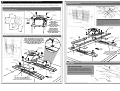
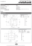
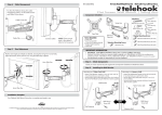
C
Attaching the Display to the Wall Plate
Installation Instructions
C.1. Attaching the Display to the Wall Plate
TELEHOOK
C.2. Pivot Head Load Capacity Adjustment
Note: This procedure will require two persons
M12 Hex Nut
30”-50” UNIVERSAL ROTATING WALL MOUNT
Tighten
Important Notes
The
Telehook 30-50 Universal Rotating Wall Mount supports flat panel displays from 30” (76cm) to 50” (127cm)
and supports a maximum load of 85kgs (187lbs).
Adjusting the Pivot Head to suit the weight of the
Display
Back Plate
Mounting
Slots
Note: For demonstration purposes, the wall
has been omitted from the above image.
With the mount attached to the display, lift the
display and slide the Back Plate into the Mounting
slots to ensure a secure connection.
D
The Pivot head is factory set to hold
approximately 35kgs (77lbs). If the display is not
holding its position when placed on the wall it
may be necessary to remove the display from
the wall and tighten the M12 Hex Nut on the
back of the Pivot Head using a 17mm (11/16”)
socket wrench or shifter. To achieve a one-touch
effortless adjustment setting it is advised that the
nut be tightened at half turns and re-tested, until
the desired friction is achieved. Alternatively the
M12 Hex Nut can be over tightened in order to
lock the display in position.
This product is factory set to support 35kgs (77lbs), and will need to be adjusted if the display is heavier or lighter.
The manufacturer does not accept responsibility for incorrect installation.
Component Checklist
Bits Box
Extension Plate
For additional security,
it is suggested that a
Padlock be attached to
the Back plate as shown.
The Padlock (not supplied)
should have a shackle
diameter no larger than
4mm ( 3/16”).
Coach
Screw (x4)
Masonry Wall
Plug (x4)
Spacer
Bush (x4)
Large
Washer (x4)
Allen Key
M6x16mm Socket
Drive Screw (x12)
Bracket Plate (x2)
TOOLS REQUIRED:
Power Drill
12mm or 8mm Drill Bit
Phillips Head Screw Driver
Spirit Level
17mm (11/16”) Socket Wrench
or Shifter
A
Bracket (x2)
Small
Washer (x4)
Wall Plate
M6x16mm
Phillips Head
Screw (x6)
M5x16mm
Phillips Head
Screw (x6)
M4x16mm
Phillips Head
Screw (x6)
Multi
Washer (x4)
Mounting the Wall Plate
Masonry Wall
Masonry
Wall Plug
Timber Stud Wall
TIP: Use a spirit
level to ensure the
wall plate is
horizontal
12mm (1/2 ”)
Hole
Mounting Slot
Wall Plate
Note: It is recommended to
mount the Wall Plate by firmly
fixing the four Coach Screws
into two studs. However, if the
weight of the display is less than
50kgs (110lbs), it is possible to
mount the Wall Plate to one stud
by fixing the two Coach Screws
through the two Centre holes.
TIP: Use a spirit
level to ensure the
wall plate is
horizontal
Timber
Stud
8mm ( 5 /16”)
Hole
Centre Holes
Shackle 4mm ( 3 /16”)
diameter or less
Back plate
M8x20mm
Phillips Head
Screw (x4)
Pivot Head
Security Option
Note: For demonstration purposes, the display
has been omitted from the image below.
Mounting
Screws
Padlock
Note: Ensure the Wall Plate
is mounted with the narrow
end of the Mounting Slot
at the bottom.
Coach Screw
Due to continuing product development, the manufacturer reserves the right to alter specifications without notice. Published: 18.04.07 ©
Large Washer
Note: Ensure the Wall Plate is
mounted with the narrow end of the
Mounting Slot at the bottom.
Large
Washer
Coach Screw
B
Choosing and Assembling the Correct Mounting Configuration
Measure the mounting hole pattern on the back of the display. Select the appropriate configuration (either 1, 2
or 3) that best suits the mounting hole pattern of the display then attach the product to the display as shown.
Configuration 3: 260mm to 660mm (101/4 ”-26”) x 200mm to 400mm (8”-153/4 ”)
Mounting Hole Patterns
M6 Screw
Hole
100mm
(4”)
Back
of Display
Top of
Display
400mm
(153 /4”)
200mm (8”)
ii
Multi Washer
200mm
(8”)
Note: The
100mmx200mm
mounting
configuration is
shown. For mounting
displays with
100mmx100mm
mounting hole
patterns, use the
100mmx100mm holes
in the Pivot Head.
100mm
(4”)
M8 Screw
Hole
M4 & M5
Screw Hole
Mounting Screw
Pivot Head
100mm
(4”)
Attaching the Bracket to the Display
260mm
(101/4”)
Configuration 1: VESA Compliant 100mmx100mm (4”x4”) & 100mmx200mm (4”x8”)
Mounting Hole Patterns
Slot
In order to ensure the display is securely attached to the
bracket it is recommended that the bracket be fastened with the
mounting screws aligned along the bottom edge of the slots.
It is also important that you use the supplied Multi Washer and
ensure that the tightest fitting hole in the washer is used for the
specific size screw
660mm (26”)
M6 Socket
Drive Screw
Pivot Head
Configuration 2: 200mmx200mm to 400mm (8”x8”-153/4 ”) Mounting Hole Patterns
Note: If the display has a vertical
mounting distance of 200mm and
requires the use of the M6 Mounting
Screws, it will be necessary to
substitute the MuIti Washers for the
small washers provided.
200mm 400mm
(153 /4”)
(8”)
Pivot Head
Bracket
Plate
Extension
Plate
Multi Washer
M6 Mounting
Screw
Small
Washer
M6 Socket
Drive Screw
Top of
Display
200mm
(8”)
Note: When assembling the
product, ensure the Telehook
Badges are positioned towards the
bottom of the display
Telehook
Badge
Mounting
Screw
Multi Washer
Spacer Bush
Mounting Screw
Spacer Bush Assembly
Back
of Display
Multi Washer
If the mounting holes are recessed into the
back of the display, use the supplied Spacer
Bushes to pack the recessed hole and ensure
that the bracket is securely fixed to the display.
Telehook
Badge
Bracket
Bracket
Bracket
Plate
Note: When assembling the product,
ensure the red Telehook Badges are
positioned towards the bottom of the display
Mounting
Screw
Spacer Bush
Top of
Display
Back
of Display
Recessed Hole