1
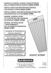
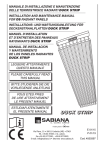
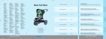
X50 Barebone
DE
Einbauanleitung
EN
1
6
2
7
Installation Instructions
FR
Guide d‘installation
A
C
B
A
3
8
4
9
5
10
B
A
F
D
C
G
H
E
I
X50 Barebone
DE
Einbauanleitung
EN
Installation Instructions
FR
Guide d‘installation
In der Barebone-Version wird das Gerät ohne Speicher und
Festplatte ausgeliefert. Bitte beachten Sie die Hinweise in
dieser Anleitung, wenn Sie Komponenten bestücken oder
austauschen möchten. Das Gerät verfügt über zwei SO-DIMMSteckplätze für max. 2x 1GB DDR2-667/800 und einen 2,5Zoll-Schacht für eine Serial-ATA-Festplatte.
As a barebone, the device is delivered without memory and
hard drive. Please note the following when installing or
removing certain components. The device features two
SO-DIMM slots for a maximum capacity of 2x 1GB DDR2667/800 memory and one 2.5 inch drive bay for one S-ATA
hard disk.
Cette version barebone ne dispose pas de disque dur ni de
mémoire vive pré-installés. Veillez à bien suivre les points
suivants lors de l'intégration ou l'échange de composants. Ce
produit est équipé de deux emplacements mémoire de type
SO-DIMM (maximum 2x 1Go DDR2-667/800) et d'un
emplacement pour disque dur 2,5'' S-ATA.
Bitte beachten Sie:
A Der Eingriff darf nur durch geschultes Fachpersonal vorgenommen werden.
B Bei unsachgemässer Handhabung könnten Beschädigungen
des Gerätes auftreten, diese sind nicht über die Gewährleistung abgedeckt.
C Um Beschädigungen von elektronischen Komponenten
durch elektrostatische Entladungen (ESD) zu vermeiden,
muss die statische Elektrizität Ihres Körpers stets abgeleitet
werden, bevor Sie elektronische Komponenten berühren.
Verwenden Sie nach Möglichkeit eine Handgelenk-Erdung und
antistatische Bodenmatten und Arbeitsflächen.
Please note and proceed as follows:
A Only authorized and skilled personnel must intervent
B Improper handling might damage the device which is not
covered by warranty
C To avoid damage of electronical components by
electrostatic discharge (ESD), ensure that the static electricity
of your body is diverted permanently before you touch
electronical components. Use an earthing wrist strap and an
anti-static ground mat, if possible.
Veuillez noter les points suivants:
A L'intégration ou les modifications doivent être réalisées par
une personne qualifiée.
B En cas de dommages résultant d'une mauvaise
manipulation, le service de garantie les concernant sera annulé.
C Afin de ne pas endommager les composants par
l'électricité statique que votre corps emmagasine, il vous faut
utiliser un tapis de sol, un plan de travail ainsi qu'un bracelet
anti-électricité-statique.
1 Disconnect the device from the mains and put it on a soft
base with the display facing downward and fold the stand
vertically upward. Next, carefully remove the cap with the
Shuttle logo that is clicked into place by six hooks. Carefully
press the side of the cap with your fingertips to loosen it.
Otherwise the cap can be loosened using a plastic card.
2 Loosen the four cross-head screws (or Phillips screws) to
remove the stand
3 Remove the four cross-head screws that fix the case
cover
4 The case cover is clicked into place by several hooks.
At the bottom of the case is a notch that can be used to lever
the case cover out of place by carefully using a screwdriver
or plastic card. Be sure to apply only little force in order not to
break the hooks.
5 As the next step, remove the large electromagnetic
shielding (EMI cover). This metal sheet is fixed by three
cross-head screws.
6 Another shielding is fixed by four screws. Only remove this
part to install or exchange memory modules. To remove such
memory modules, carefully bend back the cramps on both
sides of the module. Please see the notch when installing the
module to make sure it faces in the right direction.
7 Loosen the four screws of the drive cage A including the
affixed fan B with its small board C while leaving the cables
connected.
8 Please insert a 2.5 inch S-ATA hard disk with the
connectors facing towards the metal sheet into the drive
cage. Please then fix the hard disk with four screws and
carefully push it in afterwards to connect it.
9 Remove the protective foil on the adhesive tape that is
attached to the fan. Then fix the drive cage with the fan and
board with four screws.
10 Please re-mount the two electromagnetic shieldings, the
case cover and the stand vice versa. Finally, click the cap
with the Shuttle logo back into place and cover the four
screw holes with the self-adhesive rubber coverings included
in the delivery scope.
1 Débranchez l'appareil de la prise électrique et posez la
face de l'écran sur une surface douce, le pied relevé en mode
poignée de transport. Puis, désengagez les six " clips " du
cache arrière comportant le logo Shuttle. Relevez légèrement
le cache avec l'extrémité d'un doigt pour le dégager
complètement. Il est également possible d'utiliser une carte
plastique et de la faire glisser autour du cache.
2 Desserrez les 4 vis cruciformes afin de libérer le pied.
3 Puis ôtez les 4 vis cruciformes qui maintiennent le cache
arrière du châssis.
4 Dégager délicatement les "clips" du cache arrière à l'aide
d'une carte plastique. Attention, une trop forte tension
pourrait endommager les attaches.
5 Desserrez les 4 vis cruciformes et libérez la protection
électromagnétique.
6 Une seconde protection est fixée par 4 vis supplémentaires.
Cette partie n'est à démonter que si l'on désire accéder aux
emplacements de la mémoire vive. Pour remplacer ou ajouter
un module, écartez avec précaution les clapets latéraux des
emplacements. Veillez à bien orienter le module avant son
insertion.
7 Desserrez les 4 vis cruciformes du berceau de disque dur
A et de la fixation du ventilateur B sur la platine C . Laisser
le câble connecté.
8 Insérez un disque dur 2.5'' avec interface serial-ATA. Fixez
le disque dur au berceau avec 4 vis, et insérez le dans son
emplacement en vous assurant que les contacts soient établis.
9 Sur le ventilateur se trouve un autocollant double-face
protecteur qui doit être enlevé. Puis remontez l'ensemble
ventilateur et platine avec les 4 vis.
10 Remontez les deux protections électromagnétiques, le
cache arrière du châssis et le pied, puis ré-emboitez le cache
comportant le logo Shuttle. Enfin couvrez les vis avec les
caches livrés avec votre barebone.
1 Trennen Sie das Gerät vom Stromnetz und legen Sie es mit
dem Display nach unten auf eine weiche Unterlage und
klappen Sie den Ständer senkrecht nach oben. Zunächst wird
der Deckel mit dem Shuttle-Logo entfernt, welcher mit 6
Haken eingerastet ist. Pressen Sie dazu vorsichtig mit den
Fingerkuppen seitlich gegen den Shuttle-Deckel um ihn zu
lösen. Alternativ lässt sich der Deckel auch aushebeln, indem
man eine Plastikkarte von der Bügelöffnung an abwärts unter
die Abdeckung gleiten lässt.
2 Lösen Sie 4 Kreuzschlitzschrauben, um die Ständer-Mechanik
zu entfernen.
3 Entfernen Sie die 4 Kreuzschlitzschrauben des Gehäusedeckels.
4 Der Gehäusedeckel ist mit mehreren Haken in das Gehäuse
eingerastet. Am unteren Ende des Deckels befindet sich eine
Kerbe, an der sich der Deckel mittels Schraubendreher oder
Plastikkarte aushebeln lässt. Wenden Sie hierbei nur wenig
Kraft auf, damit die Haken nicht abbrechen.
5 Lösen sie die 3 Kreuzschlitzschrauben um die große
elektromagnetische Abschirmung zu entfernen.
6 Eine weitere Abschirmung ist mit 4 Schrauben befestigt.
Dieses Teil muss nur dann entfernt werden, wenn man
Speichermodule einbauen bzw. umrüsten möchte. Zum
Herausnehmen der Module biegen Sie die seitlichen Klammern
leicht nach außen. Beachten Sie beim Einsetzen die korrekte
Ausrichtung des Moduls anhand der Kerbe in der Kontaktleiste.
7 Lösen Sie die 4 Schrauben der Festplattenhalterung A mit
dem daran befestigten Lüfter B mit der kleinen Platine C .
Lassen Sie die Kabel dabei verbunden.
8 Setzen Sie in die Halterung eine 2,5-Zoll-Festplatte mit
Serial-ATA-Schnittstelle so ein, dass die Leiterplatte zum Blech
zeigt. Die Festplatte wird mit vier Schrauben an der Halterung
befestigt und anschließend behutsam eingeschoben, so dass
sich die Kontakte verbinden.
9 An dem Lüfter befindet sich ein doppelseitiger Klebestreifen,
dessen Schutzfolie entfernt werden muss. Danach wird die
Festplattenhalterung mit dem Lüfter und der Platine wieder
mit 4 Schrauben festgeschraubt.
10 Montieren Sie wieder die beiden Abschirmbleche, den Gehäusedeckel und den Ständer in umgekehrter Reihenfolge,
dann rasten Sie den Deckel mit dem Shuttle-Logo wieder ein.
Zum Schluss können die 4 Schraublöcher mit den selbstklebenden Gummiabdeckungen verdeckt werden, die sich im
Lieferumfang befinden.
Übersicht über die Bestandteile des demontierten Gerätes:
A kleine Abschirmung, B Speichermodule, C Deckel mit
Shuttle-Logo, D große Abschirmung, E Ständer-Mechanik,
F Gehäusedeckel, G Festplatte, H Festplattenhalterung,
I X50-Chassis
Overview of parts:
A little shielding, B memory modules, C cap with Shuttle
logo, D large shielding, E stand, F case cover,
G hard disk, H drive cage, I X50-chassis
Aperçu des pièces démontées du barebone:
A petite protection, B modules de mémoire, C cache avec
le logo Shuttle, D grande protection, E charnière du pied,
F cache arrière du châssis, G disque dur, H berceau du
disque dur, I Châssis du X50