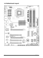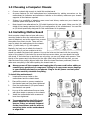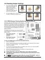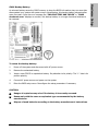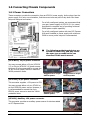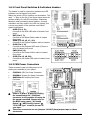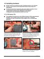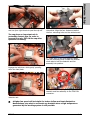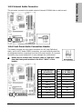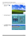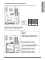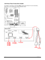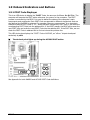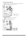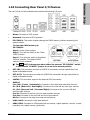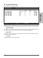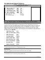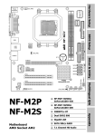
1
Hardware Setup IP35 Pro Motherboard Socket 775 User’s Manual BIOS Setup FSB 1333 MHz Dual PCI-E X16 Slots Dual Gigabit LAN 6x Internal, 2x External SATA 3Gb/s Connectors USB 2.0 / IEEE 1394 7.1-Channel HD Audio Multilingual QIG Dual Channel DDR2 800 Driver & Utility Intel P35 / ICH9R abit uGuru™ Technology External CMOS Clearing Switch Quick Power & Reset Button Vista Premium HW Ready Appendix abit Silent OTES™ Technology About this Manual: This user’s manual contains all the information you may need for setting up this motherboard. To read the user’s manual of PDF format (readable by Adobe Reader), place the “Driver & Utility CD” into the CD-ROM drive in your system. The auto-run screen will appear, click the “Manual” tab to enter its submenu. If not, browse the root directory of the CD-ROM via the File Manager, and double click the “AUTORUN” file. IP35 Pro User’s Manual English + Multilingual QIG P/N: 4310-0000-89 Rev. 2.00, May 2007 Copyright and Warranty Notice The information in this document is subject to change without notice and does not represent a commitment on part of the vendor, who assumes no liability or responsibility for any errors that may appear in this manual. No warranty or representation, either expressed or implied, is made with respect to the quality, accuracy or fitness for any particular part of this document. In no event shall the manufacturer be liable for direct, indirect, special, incidental or consequential damages arising from any defect or error in this manual or product. Product names appearing in this manual are for identification purpose only and trademarks and product names or brand names appearing in this document are the property of their respective owners. This document contains materials protected under International Copyright Laws. All rights reserved. No part of this manual may be reproduced, transmitted or transcribed without the expressed written permission of the manufacturer and authors of this manual. If you do not properly set the motherboard settings, causing the motherboard to malfunction or fail, we cannot guarantee any responsibility. The Following Information is Only for EU-member States: Directive 2002/96/EC on Waste Electrical and Electronic Equipment (WEEE): The use of the symbol indicates that this product may not be treated as household waste. By Ensuring this product is disposed of correctly, you will help prevent potential negative consequences for the environment and human health, which could otherwise be cause by inappropriate waste handling of this product. For more detailed information about recycling of this product, please contact your local city office, your household waste disposal service or the shop where you purchased the product. ii IP35 Pro Hardware Setup Contents 1. Hardware Setup ............................................................... 1-1 1.1 1.2 1.3 1.4 1.5 BIOS Setup Specifications............................................................................... 1-1 Motherboard Layout ..................................................................... 1-2 Choosing a Computer Chassis ....................................................... 1-3 Installing Motherboard ................................................................. 1-3 Checking Jumper Settings............................................................. 1-4 1.5.1 CMOS Memory Clearing Header and Backup Battery .............. 1-4 1.6 Connecting Chassis Components ................................................... 1-6 1.6.1 Power Connectors ............................................................... 1-6 1.6.2 Front Panel Switches & Indicators Headers ........................... 1-7 1.6.3 FAN Power Connectors ........................................................ 1-7 1.7 Installing Hardware ...................................................................... 1-8 1.7.1 CPU Socket 775................................................................... 1-8 1.7.2 DDR2 Memory Slots........................................................... 1-10 1.7.3 PCI Express X16 Add-on Slots (Install Graphics Card) .......... 1-11 1.8 Connecting Peripheral Devices .................................................... 1-12 1.8.1 Floppy and IDE Disk Drive Connectors ................................ 1-12 1.8.2 Serial ATA Connectors ....................................................... 1-13 1.8.3 Additional USB 2.0 Port Headers......................................... 1-14 1.8.4 Additional IEEE 1394 Port Headers ..................................... 1-14 1.8.5 Internal Audio Connector ................................................... 1-15 1.8.6 Front Panel Audio Connection Header ................................. 1-15 1.8.7 S/PDIF Output Connection Header...................................... 1-17 1.8.8 PCI and PCI Express X1 Slots ............................................. 1-17 1.8.9 Guru Panel Connection Header........................................... 1-18 1.9 Onboard Indicators and Buttons.................................................. 1-19 1.9.1 POST Code Displayer ......................................................... 1-19 1.9.2 Power Source Indicators .................................................... 1-20 1.9.3 Onboard Buttons ............................................................... 1-20 1.10 Connecting Rear Panel I/O Devices ........................................... 1-21 Driver & Utility Multilingual QIG 2. BIOS Setup....................................................................... 2-1 IP35 Pro Appendix 2.1 μGuru™ Utility .............................................................................. 2-2 2.1.1 OC Guru ............................................................................. 2-2 2.1.2 ABIT EQ.............................................................................. 2-4 2.2 Standard CMOS Features............................................................ 2-10 2.3 Advanced BIOS Features ............................................................ 2-13 2.4 Advanced Chipset Features......................................................... 2-16 2.5 Integrated Peripherals ................................................................ 2-17 2.6 Power Management Setup .......................................................... 2-21 2.7 PnP/PCI Configurations .............................................................. 2-23 2.8 Load Fail-Safe Defaults............................................................... 2-24 2.9 Load Optimized Defaults............................................................. 2-24 2.10 Set Password ........................................................................... 2-24 2.11 Save & Exit Setup..................................................................... 2-24 2.12 Exit Without Saving .................................................................. 2-24 iii 3. Driver & Utility ................................................................. 3-1 3.1 CD-ROM AUTORUN ...................................................................... 3-1 3.2 Intel Chipset Software Installation Utility ....................................... 3-2 3.3 Intel Matrix Storage Manager........................................................ 3-2 3.4 Audio Driver ................................................................................ 3-3 3.5 LAN Driver................................................................................... 3-4 3.6 JMicron SATA Driver..................................................................... 3-4 3.7 USB 2.0 Driver ............................................................................. 3-4 3.8 abit μGuru ................................................................................... 3-5 3.9 SATA RAID Driver (for Windows Vista) .......................................... 3-6 3.10 SATA RAID Driver (for Windows XP, 2003, or 2000) ..................... 3-6 4. Multilingual Quick Installation Guide .............................. 4-1 4.1 Français//Guide d'Installation Rapide............................................. 4-1 4.2 Deutsch//Kurze Installationsanleitung............................................ 4-2 4.3 Italiano//Guida all’installazione rapida ........................................... 4-3 4.4 Español//Guía rápida de instalación............................................... 4-4 4.5 Português//Guia de instalação rápida ............................................ 4-5 4.6 Русский//Краткое руководство по установке .............................. 4-6 4.7 Eesti//Kiirpaigaldusjuhend ............................................................ 4-7 4.8 Latviski//Ātrās instalēšanas instrukcija........................................... 4-8 4.9 Lietuvių//Trumpas instaliavimo vadovas ........................................ 4-9 4.10 Polski//Instrukcja szybkiej instalacji ........................................... 4-10 4.11 Magyar//Gyorstelepítési útmutató.............................................. 4-11 4.12 Türkçe//Hızlı Kurulum Kılavuzu.................................................. 4-12 4.13 ةيبرعلا ةغللا// عيرسلا بيكرتلا ليلد....................... 4-13 4.14 یسراف// عیرس بصن یامنﻩار............................................... 4-14 4.15 日本語//クイックインストールガイド ...................................... 4-15 4.16 한국어//빠른 설치 가이드 ....................................................... 4-16 4.17 Bahasa Malaysia//Panduan Pemasangan Ringkas ....................... 4-17 4.18 ไทย//คู่มือการติดตั้งอย่างย่อ ........................................................ 4-18 4.19 繁體中文................................................................................. 4-19 4.19.1 規格 ............................................................................... 4-19 4.19.2 快速安裝略說.................................................................. 4-20 4.20 简体中文................................................................................. 4-21 4.20.1 规格 ............................................................................... 4-21 4.20.2 快速安装略说.................................................................. 4-22 5. Appendix .......................................................................... 5-1 5.1 POST Code Definitions.................................................................. 5-1 5.1.1 AWARD POST Code Definitions............................................. 5-1 5.1.2 AC2005 POST Code Definitions............................................. 5-4 5.2 Troubleshooting (How to Get Technical Support?).......................... 5-5 5.2.1 Q & A ................................................................................. 5-5 5.2.2 Technical Support Form....................................................... 5-8 5.2.3 Contact Information............................................................. 5-9 iv IP35 Pro Hardware Setup 1. Hardware Setup 1.1 Specifications CPU • LGA775 Socket for Intel processor of: Core 2 Extreme Edition / Core 2 Quad / Core 2 Duo, & Pentium Extreme Edition / Pentium Dual Core / Pentium D / Pentium 4. • Supports FSB 1333MHz Chipset • Intel P35 / ICH9R Memory • 4x 240-pin DIMM slots support maximum memory capacity up to 8GB. • Supports Dual Channel DDR2 800/667 Un-buffered Non-ECC memory. LAN • Onboard Dual Gigabit LAN Controller Audio • Onboard 7.1-Ch HD Audio Codec • Supports S/PDIF In/Out • HDMI Audio Header Ready Serial ATA • 6x Internal SATA 3Gb/s connectors offered by Intel ICH9R support Intel Matrix Storage Tech (AHCI & RAID 0, 1, 5, and 10). • 2x External SATA 3Gb/s connectors offered by JMicron JMB363 support RAID 0, 1, and JBOD. IEEE 1394 • Supports 2x IEEE 1394a ports at 400Mb/s transfer rate. Expansion Slots • 1x PCI-E X16 Slot (X16 Bandwidth) • 1x PCI-E X16 Slot (X4 Bandwidth) ※ • 1x PCI-E X1 Slot • 3x PCI Slots Internal I/O Connectors • • • • • • • • • 1x 1x 6x 4x 2x 1x 1x 1x 1x Floppy Port Ultra ATA 133 IDE Connector SATA 3Gb/s Connectors USB 2.0 Headers IEEE 1394 Headers FP-Audio Header CD-In Connector S/PDIF Out Header GURU Header Rear Panel I/O • • • • • • • • • 1x 1x 1x 1x 1x 2x 1x 4x 2x PS/2 Keyboard Connector PS/2 Mouse Connector External CMOS Clearing Switch Optical S/PDIF In Connector Optical S/PDIF Out Connector eSATA Connectors 7.1-Ch Audio Connector USB 2.0 Connectors RJ-45 Gigabit LAN Connectors abit Engineered • • • • abit uGuru™ Technology abit Silent OTES™ Technology External CMOS Clearing Switch Quick Power & Reset Button RoHS • 100% Lead-free Process and RoHS Compliant Miscellaneous • ATX Form Factor (305mm x 245mm) • Vista Premium HW Ready Specifications and information contained herein are subject to change without notice. IP35 Pro 1-1 1.2 Motherboard Layout 1-2 IP35 Pro • Choose a chassis big enough to install this motherboard. • As some features for this motherboard are implemented by cabling connectors on the motherboard to indicators and switches or buttons on the chassis, make sure your chassis supports all the features required. • If there is a possibility of adopting some more hard drives, make sure your chassis has sufficient power and space for them. • Most chassis have alternatives for I/O shield located at the rear panel. Make sure the I/O shield of the chassis matches the I/O port configuration of this motherboard. You can find an I/O shield specifically designed for this motherboard in its package. 1.4 Installing Motherboard Most computer chassis have a base with many mounting holes to allow the motherboard to be securely attached, and at the same time, prevent the system from short circuits. There are two ways to attach the motherboard to the chassis base: (1) with studs, or (2) with spacers. Basically, the best way to attach the board is with studs. Only if you are unable to do this should you attach the board with spacers. Line up the holes on the board with the mounting holes on the chassis. If the holes line up and there are screw holes, you can attach the board with studs. If the holes line up and there are only slots, you can only attach with spacers. Take the tip of the spacers and insert them into the slots. After doing this to all the slots, you can slide the board into position aligned with slots. After the board has been positioned, check to make sure everything is OK before putting the chassis back on. ※ Always power off the computer and unplug the AC power cord before adding or removing any peripheral or component. Failing to so may cause severe damage to your motherboard and/or peripherals. Plug in the AC power cord only after you have carefully checked everything. Locate all the screw holes on the motherboard and the chassis base. 2. Place all the studs or spacers needed on the chassis base and have them tightened. 3. Face the motherboard’s I/O ports toward the chassis’s rear panel. 4. Line up all the motherboard’s screw holes with those studs or spacers on the chassis. 5. Install the motherboard with screws and have them tightened. ※ To prevent shorting the PCB circuit, please REMOVE the metal studs or spacers if they are already fastened on the chassis base and are without mounting-holes on the motherboard to align with. IP35 Pro Face the chassis’s rear panel. To install this motherboard: 1. 1-3 Hardware Setup 1.3 Choosing a Computer Chassis 1.5 Checking Jumper Settings • • For a 2-pin jumper, plug the jumper cap on both pins will make it CLOSE (SHORT). Remove the jumper cap, or plug it on either pin (reserved for future use) will leave it at OPEN position. SHORT OPEN OPEN Pin 1~2 SHORT Pin 2~3 SHORT For 3-pin jumper, pin 1~2 or pin 2~3 can be shorted by plugging the jumper cap in. 1.5.1 CMOS Memory Clearing Header and Backup Battery The time to clear the CMOS memory occurs when (a) the CMOS data becomes corrupted, (b) you forgot the supervisor or user password preset in the BIOS menu, (c) you are unable to boot-up the system because the CPU ratio/clock was incorrectly set in the BIOS menu, or (d) whenever there is modification on the CPU or memory modules. This header uses a jumper cap to clear the CMOS memory and have it reconfigured to the default values stored in BIOS. • Pins 1 and 2 shorted (Default): Normal operation. • Pins 2 and 3 shorted: Clear CMOS memory. To clear the CMOS memory and load in the default values: 1. Power off the system. 2. Set pin 2 and pin 3 shorted by the jumper cap. Wait for a few seconds. Set the jumper cap back to its default settings --- pin 1 and pin 2 shorted. 3. Power on the system. 4. For incorrect CPU ratio/clock settings in the BIOS, press <Del> key to enter the BIOS setup menu right after powering on system. 5. Set the CPU operating speed back to its default or an appropriate value. 6. Save and exit the BIOS setup menu. ※ Another easy way to clear the CMOS memory can be done by switching “EZ-CCMOS1”, see the section of “Connecting Rear Panel I/O Devices” in this manual for detail. The C.C. POST Code appears when either the external “EZ-CCMOS1” switch or the internal “CCMOS1” jumper is not set to its normal position. 1-4 IP35 Pro ※ An onboard battery saves the CMOS memory to keep the BIOS information stays on even after disconnected your system with power source. Nevertheless, this backup battery exhausts after some five years. Once the error message like “CMOS BATTERY HAS FAILED” or “CMOS checksum error” displays on monitor, this backup battery is no longer functional and has to be renewed. To renew the backup battery: 1. Power off the system and disconnect with AC power source. 2. Remove the exhausted battery. 3. Insert a new CR2032 or equivalent battery. Pay attention to its polarity. The “+” side is its positive polarity. 4. Connect AC power source and power on the system. 5. Enter the BIOS setup menu. Reconfigure the setup parameters if necessary. CAUTION: ※ Danger of explosion may arise if the battery is incorrectly renewed. ※ Renew only with the same or equivalent type recommended by the battery manufacturer. ※ Dispose of used batteries according to the battery manufacturer’s instructions. IP35 Pro 1-5 Hardware Setup CMOS Backup Battery: 1.6 Connecting Chassis Components 1.6.1 Power Connectors These connectors provide the connection from an ATX12V power supply. As the plugs from the power supply fit in only one orientation, find the correct one and push firmly down into these foolproof-designed connectors. For a fully configured system, we recommend that you use a power supply of ATX12V 2.0 (or newer) specification compliant and of providing minimum 400W power output capability. For a fully configured system with two PCI Express X16 cards installed, a power supply with minimum 500W or more power output is recommended. ※ The following motherboard photos are served for DEMO only, and may not be the same type or model as the one described in this user’s manual. [ATXPWR1]: 24-pin power connector You may connect either a 20-pin (ATX12V 1.3) or 24-pin (ATX12V 2.0) power source. However, it is recommended to connect the 24-pin ATX12V power source to meet the 240VA protection limits. Plugged from a 24-pin ATX12V power. Plugged from a 20-pin ATX12V power. Plugged from a 4-pin ATX12V power. Plugged from an 8-pin EPS12V power. [ATX12V1]: 8-pin power connector This connector supplies +12V power to CPU. You may connect either a 4-pin ATX12V or an 8-pin EPS12V power source. However, it is recommended to connect the 8-pin EPS12V power source to meet the 240VA protection limits. [ATX4P1]: Auxiliary 12V power connector This connector provides an auxiliary power source for devices added on PCI Express slots. 1-6 IP35 Pro Hardware Setup 1.6.2 Front Panel Switches & Indicators Headers This header is used for connecting switches and LED indicators on the chassis front panel. Watch the power LED pin position and orientation. The mark “+” align to the pin in the figure below stands for positive polarity for the LED connection. Please pay attention when connecting these headers. A wrong orientation will only result in the LED not lighting, but a wrong connection of the switches could cause system malfunction. • HLED (Pin 1, 3): Connects to the HDD LED cable of chassis front panel. • RST (Pin 5, 7): Connects to the Reset Switch cable of chassis front panel. • SPKR (Pin 13, 15, 17, 19): Connects to the System Speaker cable of chassis. • SLED (Pin 2, 4): Connects to the Suspend LED cable (if there is one) of chassis front panel. • PWR (Pin 6, 8): Connects to the Power Switch cable of chassis front panel. • PLED (Pin 16, 18, 20): Connects to the Power LED cable of chassis front panel. 1.6.3 FAN Power Connectors These connectors each provide power to the cooling fans installed in your system. • CPUFAN1: CPU Fan Power Connector • SYSFAN1: System Fan Power Connector • AUXFAN1~4: Auxiliary Fan Power Connector ※ Either a 3-pin or 4-pin CPU cooling fan connected to the “CPUFAN1” connector is still capable of having its fan speed controlled. Please refer to the BIOS setup route: “PC Health Status” “ABIT FanEQ Control” “CPU FAN Type” to select the one of your own. ※ These fan connectors are not jumpers. DO NOT place jumper caps on these connectors. IP35 Pro 1-7 1.7 Installing Hardware ※ DO NOT scratch the motherboard when installing hardware. An accidental scratch of a tiny surface-mount component may seriously damage the motherboard. ※ In order to protect the contact pins, please pay attention to these notices: 1. A maximum 20 cycles of CPU installation is recommended. 2. Never touch the contact pins with fingers or any object. 3. Always put on the cap when the CPU is not in use. 1.7.1 CPU Socket 775 ※ The installation procedures vary with different types of CPU fan-and-heatsink assembly. The one shown here is served for demo only. For detailed information on how to install the one you bought, refer to its installation guidelines. 1. Place the board so that the lever-hook of the socket is on your left side. Use your left thumb and forefinger to hold the lever hook, pull it away from the retention tab. Rotate the lever to fully open position. 2. Use your right-thumb to raise the load plate. Lift it up to fully open position. 1-8 3. Use your right thumb and forefinger to grasp the CPU package. Be sure to grasp on the edge of the substrate, and face the Pin-1 indicator toward the bottom-left side. Aim at the socket and place the CPU package vertical down into the socket. 4. Visually inspect if the CPU is seated well into the socket. The alignment key must be located in the notch of package. IP35 Pro Hardware Setup 5. Use your left hand to hold the load plate, and use your right thumb to peel the cap off. 8. Place the heatsink and fan assembly onto the socket. Align the four fasteners toward the four mounting holes on the motherboard. The cap plays an important role in protecting contact pins. In order to prevent bent pin, PUT ON the cap after operation or testing. 9. Press each of the four fasteners down into the mounting holes. Rotate the fastener clock-wise to lock the heatsink and fan assembly into position. 6. Lower the plate onto the CPU package. Engage the load lever while gently pressing down the load plate. 10. Attach the four-pin power plug from the heatsink and fan assembly to the CPU FAN connector. 7. Secure the lever with the hook under retention tab. ※ A higher fan speed will be helpful for better airflow and heat-dissipation. Nevertheless, stay alert to not touch any heatsink since a high temperature generated by the working system is still possible. IP35 Pro 1-9 1.7.2 DDR2 Memory Slots To reach the performance of Dual Channel DDR2, the following rules must be obeyed: • For a 2-DIMM dual-channel installation: Populate DIMM modules of the same type and size on slots [DIMM1]+[DIMM3], or slots [DIMM2]+[DIMM4]. • For a 4-DIMM dual-channel installation: Populate 2 DIMM modules of the same type and size on slots [DIMM1]+[DIMM3], and another 2 DIMM modules of the same type and size on slots [DIMM2]+[DIMM4]. ※ [DIMM1] and [DIMM3] slots are made of the same color. [DIMM2] and [DIMM4] are made of another same color. Usually there is no hardware or BIOS setup requires after adding or removing memory modules, but you will have to clear the CMOS memory first if any memory module related problem occurs. To install system memory: 1. Power off the computer and unplug the AC power cord before installing or removing memory modules. 2. Locate the DIMM slot on the board. 3. Hold two edges of the DIMM module carefully, keep away from touching its connectors. 4. Align the notch key on the module with the rib on the slot. 5. Firmly press the module into the slots until the ejector tabs at both sides of the slot automatically snap into the mounting notch. Do not force the DIMM module in with extra force as the DIMM module only fits in one direction. 6. To remove the DIMM modules, push the two ejector tabs on the slot outward simultaneously, and then pull out the DIMM module. ※ Static electricity can damage the electronic components of the computer or optional boards. Before starting these procedures, ensure that you are discharged of static electricity by touching a grounded metal object briefly. 1-10 IP35 Pro This motherboard provides dual PCI Express X16 slots for one or two graphics cards installation of graphics cards that comply with PCI Express specifications. One PCI Express graphics card installation: Insert your PCI Express graphics card into slot [PCIEXP1]. ※ Do not install only one PCI Express graphics card on slot [PCIEXP2], for such an act will pull its speed down to x4 only. Two PCI Express graphics cards installation: Install the master graphics card into slot [PCIEXP1]. Install the slave graphics card into slot [PCIEXP2]. ※ Both the graphics cards must be of the same GPU family. ※ Make sure your power supply is sufficient to provide the minimum power required. (For a fully configured system with two PCI Express X16 cards installed, a power supply with minimum 500W or more power output is recommended.) ※ Refer to the instruction guide that came with the graphics card on how to run its dual display mode. IP35 Pro 1-11 Hardware Setup 1.7.3 PCI Express X16 Add-on Slots (Install Graphics Card) 1.8 Connecting Peripheral Devices 1.8.1 Floppy and IDE Disk Drive Connectors The FDC1 connector connects up to two floppy drives with a 34-wire, 2-connector floppy cable. Connect the single end at the longer length of ribbon cable to the FDC1 on the board, the two connectors on the other end to the floppy disk drives connector. Generally you need only one floppy disk drive in your system. ※ The red line on the ribbon cable must be aligned with pin-1 on both the FDC1 port and the floppy connector. Each of the IDE port connects up to two IDE drives at Ultra ATA/100 mode by one 40-pin, 80-conductor, and 3-connector Ultra ATA/66 ribbon cables. Connect the single end (blue connector) at the longer length of ribbon cable to the IDE port of this board, the other two ends (gray and black connector) at the shorter length of the ribbon cable to the connectors of your hard drives. ※ 1-12 Make sure to configure the “Master” and “Slave” relation before connecting two drives by one single ribbon cable. The red line on the ribbon cable must be aligned with pin-1 on both the IDE port and the hard-drive connector. IP35 Pro Each SATA connector serves as one single channel to connect one SATA device by SATA cable. To connect SATA device: 1. Attach either end of the signal cable to the SATA connector on motherboard. Attach the other end to the SATA device. 2. Attach the SATA power cable to the SATA device and connect the other end from the power supply. ※ The motherboard in this photo is served for DEMO only, and may not be the same type or model as the one described in this user’s manual. IP35 Pro 1-13 Hardware Setup 1.8.2 Serial ATA Connectors 1.8.3 Additional USB 2.0 Port Headers Each header supports 2x additional USB 2.0 ports by connecting bracket or cable to the rear I/O panel or the front-mounted USB ports of your chassis. ※ Pin Pin Assignment Pin Pin Assignment 1 3 5VDUAL 2 5VDUAL Data0 - 4 Data1 - 5 Data0 + 6 Data1 + 7 Ground 8 Ground 10 NC Make sure the connecting cable bears the same pin assignment. 1.8.4 Additional IEEE 1394 Port Headers Each header supports 1x additional IEEE 1394 port by connecting bracket or cable to the rear I/O panel or the front-mounted IEEE 1394 port of your chassis. ※ 1-14 Pin Pin Assignment Pin 1 TPA0 + 2 Pin Assignment TPA0 - 3 Ground 4 Ground 5 TPB0 + 6 TPB0 - 7 +12V 8 +12V 10 Ground Make sure the connecting cable bears the same pin assignment. IP35 Pro Hardware Setup 1.8.5 Internal Audio Connector This connector connects to the audio output of internal CD-ROM drive or add-on card. 1.8.6 Front Panel Audio Connection Header This header provides the front panel connection for HD (High Definition) Audio, yet for AC’97 Audio CODEC connection, you must carefully check the pin assignment before connecting from the front panel module. An incorrect connection may cause malfunction or even damage the motherboard. ※ Please do not connect the “Ground” cable or “USB VCC” cable from the front panel module to the Pin 4 “AVCC” of this header. IP35 Pro Pin Pin Assignment (HD AUDIO) Pin Pin Assignment (AC’97 AUDIO) 1 MIC2 L 1 MIC In 2 AGND 2 GND 3 MIC2 R 3 MIC Power 4 AVCC 4 NC 5 FRO-R 5 Line Out (R) 6 MIC2_JD 6 NC 7 F_IO_SEN 7 NC 9 FRO-L 9 Line Out (L) 10 LINE2_JD 10 NC 1-15 Driver Configuration for AC’97 audio connection: The audio driver is originally configured to support HD Audio. For AC’97 audio connection, you may: 1. Right-click the “Realtek HD Audio Manager” icon in system tray. 2. Click “Audio I/O” tab, and then click “Connector Settings”. 3. Click “Disabled front panel jack detection”, and then click “OK” to confirm. 1-16 IP35 Pro Hardware Setup 1.8.7 S/PDIF Output Connection Header This header provides the S/PDIF output connection to your add-on HDMI VGA card. Pin Pin Assignment 1 VCC (5V) 2 x 3 S/PDIF Out 4 Ground 1.8.8 PCI and PCI Express X1 Slots Install PCI Express X1 cards into slot “PCIE1”. Install PCI cards into slots “PCI1”, “PCI2”, and/or “PCI3”. IP35 Pro 1-17 1.8.9 Guru Panel Connection Header This header is reserved for connecting abit’s exclusive Guru Panel. For more information, please refer to the included Guru Panel Installation Guide. 1-18 IP35 Pro 1.9.1 POST Code Displayer This is an LED device to display the “POST” Code, the acronym for Power On Self Test. The computer will execute the POST action whenever you power on the computer. The POST process is controlled by the BIOS. It is used to detect the status of the computer’s main components and peripherals. Each POST Code corresponds to different checkpoints that are also defined by the BIOS in advance. For example, “memory presence test” is an important checkpoint and its POST Code is “C1”. When the BIOS execute any POST item, it will write the corresponding POST Code into the address 80h. If the POST passes, the BIOS will process the next POST item and write the next POST Code into the address 80h. If the POST fails, we can check the POST Code in address 80h to find out where the problem lies. This LED device also displays the “POST” Code of AC2005, an “uGuru” chipset developed exclusively by abit. ※ The decimal point lights up during the AC2005 POST action. See Appendix for both AWARD and AC2005 POST Code definitions. IP35 Pro 1-19 Hardware Setup 1.9 Onboard Indicators and Buttons 1.9.2 Power Source Indicators • 3VSB: This LED lights up when the power supply is connected with power source. • VCC: This LED lights up when the system power is on. 1.9.3 Onboard Buttons • PWRSW1: Push this button to power on the system. • RESET1: Push this button to reset the system. 1-20 IP35 Pro Hardware Setup 1.10 Connecting Rear Panel I/O Devices The rear I/O part of this motherboard provides the following I/O ports: • Mouse: Connects to PS/2 mouse. • Keyboard: Connects to PS/2 keyboard. • EZ-CCMOS1: This switch enables clearing the CMOS memory without uncovering the system chassis. To clear the CMOS memory by EZ-CCMOS1: Step 1: Power off the system. Step 2: Turn left this switch to the “Clear CMOS” position. Step 3: Turn right this switch to its default “Normal” position. The default CMOS memory is now reloaded. ※ The C.C. POST Code appears when either the external “EZ-CCMOS1” switch or the internal “CCMOS1” jumper is not set to its normal position. • OPT-IN1: This connector provides an S/PDIF-In connection through optical fiber from digital multimedia devices. • OPT-OUT1: This connector provides an S/PDIF-Out connection through optical fiber to digital multimedia devices. • eSATA1: This connector supports the external SATA connection. • AUDIO1: Cen./Sub. (Center / Subwoofer): Connects to the center and subwoofer channel. R.L./R.R. (Rear Left / Rear Right): Connects to the rear left and rear right channel. S.L./S.R. (Surround Left / Surround Right): Connects to the surround left and surround right channel. Line-In: Connects to the line out from external audio sources. Line-Out: Connects to the front left and front right channel. Mic-In: Connects to the plug from external microphone. • LAN1/LAN2: Connects to Local Area Network. • USB1/USB2: Connects to USB devices such as scanner, digital speakers, monitor, mouse, keyboard, hub, digital camera, joystick etc. IP35 Pro 1-21 1-22 IP35 Pro 2. BIOS Setup This motherboard provides a programmable EEPROM so that you can update the BIOS utility. The BIOS (Basic Input/Output System) is a program that deals with the basic level of communication between processor and peripherals. Use the BIOS Setup program only when installing motherboard, reconfiguring system, or prompted to “Run Setup”. This chapter explains the Setup Utility of BIOS utility. After powering up the system, the BIOS message appears on the screen, the memory count begins, and then the following message appears on the screen: If this message disappears before you respond, restart the system by pressing <Ctrl> + <Alt> + <Del> keys, or by pressing the Reset button on the computer chassis. Only when these two methods fail should you restart the system by powering it off and then back on. After pressing <Del> key, the main menu screen appears. Phoenix – AwardBIOS CMOS Setup Utility ► uGuru Utility ► PnP/PCI Configurations ► Standard CMOS Features Load Fail-Safe Defaults ► Advanced BIOS Features Load Optimized Defaults ► Advanced Chipset Features Set Password ► Integrated Peripherals Save & Exit Setup ► Power Management Setup Exit Without Saving Esc: Quit F10: Save & Exit Setup F6 : Save PROFILE To BIOS : Select Item (P35-W627DHG-6A790A1BC-00) F7 : Load PROFILE From BIOS Change CPU’s Clock & Voltage ※ In order to increase system stability and performance, our engineering staff is constantly improving the BIOS menu. The BIOS setup screens and descriptions illustrated in this manual are for your reference only, and may not completely match with what you see on your screen. IP35 Pro 2-1 BIOS Setup PRESS DEL TO ENTER SETUP 2.1 μGuru™ Utility There are two setup menus in this μGuru utility. You may switch between these two by clicking the left or right arrow key on keyboard: 2.1.1 OC Guru μGuru Utility v1.01C OC Guru Genuine Intel(R) CPU 3.60GHz Frequency : 3672MHz X X X X X CPU Operating Speed - External Clock - Multiplier Factor - Estimated New CPU Clock - DRAM Speed (CPU:DRAM) - PCI Express Clock Item Help ► 3600(200) 204MHz X 18 3672MHz Default 100MHz ► Voltages Control Press Enter ► Power Cycle Statistics Press Enter :Move Enter:Select +/-/PU/PD:Value F8:OC On The Fly F10:Save ESC:Exit Genuine Intel(R) CPU This item displays the CPU model name installed on this motherboard. Frequency This item displays the processor speed of the CPU installed on this motherboard. CPU Operating Speed This item displays the CPU operating speed according to the type and speed of your CPU. You can also select the [User Define] option to enter the manual option. User Define: ※ The wrong settings of the multiplier and external clock in certain circumstances may cause CPU damage. Setting the working frequency higher than the PCI chipset or processor specs, may cause abnormal memory module functioning, system hangs, hard disk drive data lose, abnormal functioning of the VGA card, or abnormal functioning with other add-on cards. Using non-specification settings for your CPU is not the intention of this explanation. These should be used for engineering testing, not for normal applications. ※ There will be no guaranty for the settings beyond specification. Any damage of any component on this motherboard or peripherals resulting therein is not our responsibility. - External Clock This item selects the external clock frequency. Due to the specification limit of the CPU you installed, the speed you set over its standard bus speed is supported, but not guaranteed. 2-2 IP35 Pro - Multiplier Factor This item displays the multiplier factor for the CPU you installed. - Estimated New CPU Clock This item displays an estimated CPU processor speed. - DRAM Speed (CPU:DRAM) This item determines the DRAM frequency. Voltages Control μGuru Utility v1.01C x x x x x x x x x x OC Guru Voltage Control - Voltage Control - CPU Core Voltage - DDR2 Voltage - CPU VTT 1.2V Voltage - MCH 1.25V Voltage - ICH 1.05V Voltage - ICHIO 1.5V Voltage - DDR2 Reference Voltage - CPU GTLREF 0&2 - CPU GTLREF 1&3 Auto Detect 1.3250 C 1.800 V 1.20 V 1.25 V 1.05 V 1.50 V 0% 67% 67% Item Help ►► :Move Enter:Select +/-/PU/PD:Value F8:OC On The Fly F10:Save ESC:Exit - CPU Core Voltage This item selects the Core voltage for CPU. - DDR2 Voltage This item selects the voltage for DDR2 memory modules. - CPU VTT 1.2V Voltage This item selects the VTT voltage for CPU. - MCH 1.25V Voltage This item selects the voltage for MCH (NB). - ICH 1.05V Voltage This item selects the Core voltage for ICH (SB). - ICHIO 1.5V Voltage This item selects the I/O voltage for ICH (SB). - DDR2 Reference Voltage This item selects the reference voltage for DDR2 memory modules. IP35 Pro 2-3 BIOS Setup This option allows you to switch between the default and user-defined voltages. Leave this setting at default unless the current voltage setting cannot be detected or is not correct. The option “User Define” enables you to select the following voltages manually. - CPU GTLREF 0&2 / CPU GTLREF 1&3 These items select the percentage ratio of CPU VTT voltage for each group of the CPU GTL reference voltage. Power Cycle Statistics Click <Enter> key to enter its submenu: μGuru Utility v1.01C OC Guru Power Cycle Statistics PC Up Time PC Up Time Total PC Power Cycles PC Reset Button Cycles AC Power On Total Time AC Power Cycles 0 119 538 123 288 228 Hours Hours Cycles Cycles Hours Cycles Item Help ►► :Move Enter:Select +/-/PU/PD:Value F8:OC On The Fly F10:Save ESC:Exit These items display the power cycle statistics for each element. 2.1.2 ABIT EQ Click right-arrow <→> key to switch from OC Guru setup menu to ABIT EQ setup menu: ► ► ► ► ABIT EQ ABIT EQ Beep Control Temperature Monitoring Voltage Monitoring Fan Speed Monitoring FanEQ Control μGuru Utility v1.01C Enabled Press Enter Press Enter Press Enter Press Enter :Move Enter:Select +/-/PU/PD:Value Item Help ► F10:Save ESC:Exit ABIT EQ Beep Control This item controls if the beeper sounds or not when any warning event occurred. 2-4 IP35 Pro Temperature Monitoring Click <Enter> key to enter its submenu: μGuru Utility v1.01C ABIT EQ Temperature Monitoring Reading Shutdown Shutdown Enable Temp. (*)CPU Temperature 60°C/140°F (*) 85°/185°F ° (*)System Temperature 35°C/95°F ( ) 65° C/149°F ° (*)PWM Temperature 53°C/127°F ( ) 90° C/194°F Beep Enable (*) (*) (*) Beep Temp. 75°C/167°F 55°C/131°F 80°C/176°F BIOS Setup :Move Enter:Select +/-/PU/PD:Value F10:Save ESC:Exit CPU, System, PWM Temperature These items display the temperature of CPU, System, and Power Module. - Shutdown Enable Use <Space> key to enable system shutdown function. If the CPU/System/PWM’s temperature exceeds the shutdown temperature limit, the system will shutdown automatically. - Shutdown Temp. This item sets the temperature that will shutdown the system automatically in order to prevent system overheating. - Beep Enable Use <Space> key to enable warning beeps function. Once the system has detected that the CPU/System/PWM’s temperature exceeded the beep temperature limit, warning beeps will sound. - Beep Temp. This item selects the warning temperature limit. ※ The shutdown temperature must be set higher than the warning temperature. IP35 Pro 2-5 Voltage Monitoring Click <Enter> key to enter its submenu: μGuru Utility v1.01C ABIT EQ Voltage Monitoring Reading Shutdown Enable (*)CPU Core Voltage 1.25 V (*) (*)DDR2 Voltage 1.80 V ( ) (*)DDR2 VTT Voltage 0.89 V ( ) (*)CPU VTT 1.2V Voltage 1.20 V ( ) (*)MCH 1.25V Voltage 1.25 V ( ) (*)ICHIO 1.5V Voltage 1.50 V ( ) (*)ICH 1.05V Voltage 1.05 V ( ) (*)ATX +12V (24-Pin Connector) 12.00 V ( ) (*)ATX +12V (8-Pin Connector) 12.00 V ( ) (*)ATX +5V 5.00 V ( ) (*)ATX +3.3V 3.30 V ( ) (*)ATX 5VSB 5.00 V ( ) :Move Enter:Select +/-/PU/PD:Value Beep Enable (*) (*) (*) (*) (*) (*) (*) (*) (*) (*) (*) (*) High Limit 1.60 2.15 1.05 1.50 1.50 1.80 1.25 14.40 14.40 6.00 3.95 6.00 F10:Save V V V V V V V V V V V V Low Limit 0.00 1.45 0.70 1.00 1.00 1.20 0.85 9.60 9.60 4.00 2.65 4.00 V V V V V V V V V V V V ESC:Exit All Voltages These items display the voltage of each element. - Shutdown Enable Use <Space> key to enable system shutdown function. If the voltage of corresponding element is higher/lower than the high/low limit, the system will automatically shutdown. - Beep Enable Use <Space> key to enable warning beeps function. If the voltage of corresponding element is higher/lower than the high/low limit, warning beeps will sound. - High/Low Limit These items set the high and low voltage limit. ※ 2-6 The high limit voltage must be set higher than the low limit voltage. IP35 Pro Fan Speed Monitoring Click <Enter> key to enter its submenu: :Move Enter:Select +/-/PU/PD:Value Beep Enable (*) ( ) ( ) ( ) ( ) ( ) Low Limit 300 RPM 300 RPM 300 RPM 300 RPM 300 RPM 300 RPM F10:Save ESC:Exit BIOS Setup (*)CPU FAN Speed ( )SYS FAN Speed ( )AUX1 FAN Speed ( )AUX2 FAN Speed ( )AUX3 FAN Speed ( )AUX4 FAN Speed μGuru Utility v1.01C ABIT EQ Fan Speed Monitoring Reading Shutdown Enable 2440 RPM (*) N/A ( ) N/A ( ) N/A ( ) N/A ( ) N/A ( ) CPU/SYS/AUX1~4 FAN Speed These items display the speed of the fans connected to CPU, SYS, and AUX1~4 fan connectors. - Shutdown Enable Use <Space> key to enable system shutdown function. Once the system has detected that the fan speed is lower than the low limit value, system will shutdown automatically. - Beep Enable Use <Space> key to enable warning beeps function. If the fan speed is lower than the low limit value, warning beeps will sound. - Low Limit These items set the low limit of fan speed. IP35 Pro 2-7 FanEQ Control μGuru Utility v1.01C ABIT EQ FanEQ Control ► 1st FanEQ Group Press Enter ► 2nd FanEQ Group Press Enter :Move Enter:Select +/-/PU/PD:Value Item Help ►► F10:Save ESC:Exit 1st FanEQ Group Click <Enter> key to enter its submenu (1st FanEQ Group): μGuru Utility v1.01C ABIT EQ 1st FanEQ Group CPU FanEQ Control Enabled -Reference Temperature CPU Temperature -Control Temperature High 66°C/150°F -Control Temperature Low 35°C/95°F -Fan PWM Duty Cycle High 100 % -Fan PWM Duty Cycle Low 60 % SYS FanEQ Control Enabled -Reference Temperature SYS Temperature -Control Temperature High 40°C/104°F -Control Temperature Low 30°C/86°F -DC Fan Voltage High 12.0 V -DC Fan Voltage Low 8.0 V AUX1 FanEQ Control Enabled -Reference Temperature SYS Temperature -Control Temperature High 40°C/104°F -Control Temperature Low 30°C/86°F -DC Fan Voltage High 12.0 V -DC Fan Voltage Low 8.0 V :Move Enter:Select +/-/PU/PD:Value Item Help ►►► F10:Save ESC:Exit CPU/SYS/AUX1 FanEQ Control When set to [Enabled], these items control the CPU, SYS, and/or AUX1 fan speed by the following setting combinations. - Reference Temperature This item selects the reference point for taking temperature among the available options of CPU, SYS, and PWM Temperature. 2-8 IP35 Pro - Control Temperature High/Low These items set the high and low temperature limit that you want to do the fan speed control. - Fan PWM Duty Cycle High/Low These items set the high and low limit of PWM duty cycle that you want to provide the fan with. - DC Fan Voltage High/Low These items set the high and low voltage limit that you want to provide the fan with. ※ The high limit voltage must be set higher than the low limit voltage. BIOS Setup 2nd FanEQ Group Click <Enter> key to enter its submenu (2nd FanEQ Group): μGuru ABIT EQ 2nd FanEQ Group AUX2 FanEQ Control -Reference Temperature -Control Temperature High -Control Temperature Low -DC Fan Voltage High -DC Fan Voltage Low AUX3 FanEQ Control AUX4 FanEQ Control Utility V1.01C Enabled SYS Temperature 40°C/104°F 30°C/86°F 12.0 V 8.0 V Disabled Disabled :Move Enter:Select +/-/PU/PD:Value Item Help ►►► F10:Save ESC:Exit AUX2~AUX4 FanEQ Control When set to [Enabled], these items control the AUX2~AUX4 fan speed by the following setting combinations. - Reference Temperature This item selects the reference point for taking temperature among the available options of CPU, SYS, and PWM Temperature. - Control Temperature High/Low These items set the high and low temperature limit that you want to do the fan speed control. - DC Fan Voltage High/Low These items set the high and low voltage limit that you want to provide the fan with. ※ The high limit voltage must be set higher than the low limit voltage. IP35 Pro 2-9 2.2 Standard CMOS Features Date (mm:dd:yy) Time (hh:mm:ss) ► ► ► ► ► ► SATA SATA SATA SATA SATA SATA Channel Channel Channel Channel Channel Channel Phoenix – AwardBIOS CMOS Setup Utility Standard CMOS Features Fri, May 11 2007 12 : 34 : 56 1 3 2 4 5 6 Item Help None None None None None None Drive A Drive B Floppy 3 Mode Support Halt On 1.44M, 3.5 in. None Disabled All, But Keyboard Base Memory Extended Memory Total Memory 640K 1047552K 1047552K :Move Enter:Select +/-/PU/PD:Value F10:Save ESC:Exit F1:General Help F5: Previous Values F6: Fail-Safe Defaults F7: Optimized Defaults Date (mm:dd:yy) This item sets the date you specify (usually the current date) in the format of [Month], [Date], and [Year]. Time (hh:mm:ss) This item sets the time you specify (usually the current time) in the format of [Hour], [Minute], and [Second]. SATA Channel 1 ~ SATA Channel 6 Click <Enter> key to enter its submenu: Phoenix – AwardBIOS CMOS Setup Utility SATA Channel 1 HDD Auto-Detection Press Enter SATA Channel 1 Access Mode Item Help Auto Auto Capacity 0 MB Cylinder Head Precomp Landing Zone Sector 0 0 0 0 0 :Move Enter:Select +/-/PU/PD:Value F10:Save ESC:Exit F1:General Help F5: Previous Values F6: Fail-Safe Defaults F7: Optimized Defaults 2-10 IP35 Pro HDD Auto-Detection This item allows you to detect the parameters of hard drives by pressing <Enter> key. The parameters will be shown on the screen automatically. SATA Channel 1 ~ SATA Channel 6 When set to [Auto], the BIOS will automatically check what kind of SATA hard drive you are using. If you want to define your own drive yourself, set it to [Manual] and make sure you fully understand the meaning of the parameters. Please refer to the instruction manual provided by the device’s manufacturer to get the setting right. Access Mode Capacity This item displays the approximate capacity of the disk drive. Usually the size is slightly greater than the size of a formatted disk given by a disk-checking program. Cylinder This item configures the numbers of cylinders. Head This item configures the numbers of read/write heads. Precomp This item displays the number of cylinders at which to change the write timing. Landing Zone This item displays the number of cylinders specified as the landing zone for the read/write heads. Sector This item configures the numbers of sectors per track. Back to Standard CMOS Features Setup Menu Drive A & Drive B This item sets the type of floppy drives (usually only Drive A) installed. Floppy 3 Mode Support This item allows you to use “3 Mode Floppy Drive” in Japanese computer systems by selecting drive A, B, or both. Leave this item at its default [Disabled] setting if you are not using this Japanese standard floppy drive. Halt On This item determines whether the system stops if an error is detected during system boot-up. [All Errors]: The system-boot will stop whenever the BIOS detect a non-fatal error. [No Errors]: The system-boot will not stop for any error detected. IP35 Pro 2-11 BIOS Setup This item selects the mode to access your SATA devices. Leave this item at its default [Auto] setting to detect the access mode of your HDD automatically. [All, But Keyboard]: The system-boot will stop for all errors except a keyboard error. [All, But Diskette]: The system-boot will stop for all errors except a diskette error. [All, But Disk/Key]: The system-boot will stop for all errors except a diskette or keyboard error. Base Memory This item displays the amount of base memory installed in the system. The value of the base memory is typically 640K for systems with 640K or more memory size installed on the motherboard. Extended Memory This item displays the amount of extended memory detected during system boot-up. Total Memory This item displays the total memory available in the system. 2-12 IP35 Pro 2.3 Advanced BIOS Features Item Help :Move Enter:Select +/-/PU/PD:Value F10:Save ESC:Exit F1:General Help F5: Previous Values F6: Fail-Safe Defaults F7: Optimized Defaults CPU L3 Cache This item is used to enable the L3 cache (default setting), and appears only for certain CPU (Intel Pentium 4 processor with HT Technology Extreme Edition) that possesses L3 cache. CPU Feature Click <Enter> key to enter its submenu: Phoenix – AwardBIOS CMOS Setup Utility CPU Feature Thermal Control Enabled Limit CPUID MaxVal Disabled C1E Function Enabled Execute Disable Bit Enabled Virtualization Technology Enabled EIST Function Enabled Item Help :Move Enter:Select +/-/PU/PD:Value F10:Save ESC:Exit F1:General Help F5: Previous Values F6: Fail-Safe Defaults F7: Optimized Defaults Thermal Control This option enables or disables the thermal monitoring. Limit CPUID MaxVal When set to [Enabled], this item limits the CPUID maximum value to 3, which is usually required for older OS like Windows NT4.0. IP35 Pro 2-13 BIOS Setup Phoenix – AwardBIOS CMOS Setup Utility Advanced BIOS Features CPU L3 Cache Enabled ► CPU Feature Press Enter ► Hard Disk Boot Priority Press Enter Hyper-Threading Technology Enabled Quick Power On Self Test Enabled First Boot Device Floppy Second Boot Device Hard Disk Third Boot Device SATA CDROM Boot Other Device Enabled Boot Up Floppy Seek Disabled Boot Up NumLock Status On Security Option Setup MPS Version Ctrl For OS 1.4 Report No FDD for OS No Full Screen LOGO Show Enabled Leave this item at its default [Disabled] settings for OS like Windows XP. C1E Function This item appears only for certain processors with the C1E (Enhanced Halt State) Function. When set to [Enabled], the processor will further reduce the total power consumption. Execute Disable Bit This item appears only for certain processors with the Execute Disable Bit (XD bit) feature. When set to [Enabled], this item allows the processor to prevent data pages from being used by malicious software to execute code and provide memory protection. Virtualization Technology This option enables or disables the additional hardware capabilities provided by Virtualization Technology. EIST Function This item appears only for certain processors with the EIST (Enhanced Intel SpeedStep Technology) Function. When set to [Enabled], EIST will dynamically switch between multiple frequency and voltage points to optimize the power and performance balance of the processor and system based on demand. Back to Advanced BIOS Features Setup Menu Hard Disk Boot Priority This item selects the hard disks booting priority. By pressing <Enter> key, you can enter its submenu where the hard disks detected can be selected for the booting sequence to boot up system. This item functions only when there is the option of [Hard Disk] in any one of the First/Second/Third Boot Device items. Hyper-Threading Technology This item is used to enable the functionality of the processor with Hyper-Threading Technology and will appear only when using such processor. The Hyper-Threading Technology helps your PC work more efficiently by maximizing processor resources and enabling a single processor to run two separate threads of software simultaneously, bringing forth greater performance and system responsiveness when running multiple applications at once. Quick Power On Self Test When set to [Enabled], this item speeds up the Power On Self Test (POST) after powering on the system. The BIOS shorten or skip some check during the POST. First Boot Device / Second Boot Device / Third Boot Device / Boot Other Device Select the drive to boot first, second and third in the [First Boot Device], [Second Boot Device], and [Third Boot Device] items respectively. The BIOS will boot the operating system according to the sequence of the drive selected. Set [Boot Other Device] to [Enabled] if you wish to boot from another device other than these three items. ※ 2-14 Select the correct type of CD-ROM for the option [First Boot device] when installing OS from CD-ROM. IP35 Pro Boot Up Floppy Seek When set to [Enabled], the BIOS will check whether the floppy disk drive is installed or not. Boot Up NumLock Status This item determines the default state of the numeric keypad at system booting up. [On]: The numeric keypad functions as number keys. [Off]: The numeric keypad functions as arrow keys. Security Option [Setup]: The password is required only when accessing the BIOS Setup. [System]: The password is required each time the computer boots up. ※ Don’t forget your password. If you forget the password, you will have to open the computer case and clear all information in the CMOS before you can start up the system. But by doing this, you will have to reset all previously set options. MPS Version Ctrl For OS This item specifies which version of MPS (Multi-Processor Specification) this motherboard will use. Leave this item at its default setting. Report No FDD For OS When set to [Yes], this item allows you to run some older operating system without floppy disk drive. Leave this item at its default setting. Full Screen LOGO Show This item determines to show the full screen logo when booting. IP35 Pro 2-15 BIOS Setup This item determines when the system will prompt for password - every time the system boots or only when enters the BIOS setup. 2.4 Advanced Chipset Features x x x x x x x x x Phoenix – AwardBIOS CMOS Setup Utility Advanced Chipset Features DRAM Timing Selectable By SPD - CAS Latency Time (tCL) Auto - RAS# to CAS# Dealay (tRCD) Auto - RAS# Precharge (tRP) Auto - Precharge Delay (tRAS) Auto - Refresh Cycle Time (tRFC) Auto - Write Recovery Time (tWR) Auto - Write to Read Delay (tWTR) Auto - Act to Act Time (tRRD) Auto - Read to Precharge (tRTP) Auto PCIe Compliancy Mode v1.0a PEG Force X1 Disabled Init Display First PCI Slot Item Help :Move Enter:Select +/-/PU/PD:Value F10:Save ESC:Exit F1:General Help F5: Previous Values F6: Fail-Safe Defaults F7: Optimized Defaults DRAM Timing Selectable This item sets the optimal timings for the following four items, depending on the memory module you are using. The default setting “By SPD” configures these four items by reading the contents in the SPD (Serial Presence Detect) device. The EEPROM on the memory module stores critical parameter information about the module, such as memory type, size, speed, voltage interface, and module banks. The following items will be available to make adjustments by selecting option [Manual]. - CAS Latency Time - RAS# to CAS# Dealay (tRCD) (tCL) - RAS# Precharge (tRP) - Precharge Delay (tRAS) - Refresh Cycle Time (tRFC) - Write Recovery Time (tWR) - Write to Read Delay (tWTR) - Act to Act Time (tRRD) - Read to Precharge (tRTP) PCIe Compliancy Mode This item selects the mode for PCI Express add-on card. PEG Force X1 When set to [Enabled], this item forces the PEG port down to x1 mode. Init Display First This item allows you to choose the primary display card. 2-16 IP35 Pro 2.5 Integrated Peripherals Phoenix – AwardBIOS CMOS Setup Utility Integrated Peripherals ► OnChip SATA Device Press Enter ► OnChip PCI Device Press Enter ► Onboard PCI Device Press Enter Onboard FDC Controller Enabled Item Help OnChip SATA Device Click <Enter> key to enter its submenu: Bus Master SATA Mode Phoenix – AwardBIOS CMOS Setup Utility OnChip SATA Device Enabled IDE Item Help :Move Enter:Select +/-/PU/PD:Value F10:Save ESC:Exit F1:General Help F5: Previous Values F6: Fail-Safe Defaults F7: Optimized Defaults Bus Master This option enables or disables the bus mastering capability under the DOS environment. SATA Mode This item selects the mode for devices connected through SATA1~SATA6 ports. [IDE]: The on-chip Serial ATA served as IDE mode. [RAID]: The on-chip Serial ATA served as RAID mode. [AHCI]: The on-chip Serial ATA served as AHCI (Advanced Host Controller Interface) mode for advanced performance and usability. IP35 Pro 2-17 BIOS Setup :Move Enter:Select +/-/PU/PD:Value F10:Save ESC:Exit F1:General Help F5: Previous Values F6: Fail-Safe Defaults F7: Optimized Defaults OnChip PCI Device Click <Enter> key to enter its submenu: Phoenix – AwardBIOS CMOS Setup Utility OnChip PCI Device OnChip Audio Controller Enabled ► USB Device Setting Press Enter Item Help :Move Enter:Select +/-/PU/PD:Value F10:Save ESC:Exit F1:General Help F5: Previous Values F6: Fail-Safe Defaults F7: Optimized Defaults OnChip Audio Controller This option enables or disables the audio controller. USB Device Setting Click <Enter> key to enter its submenu: Phoenix – AwardBIOS CMOS Setup Utility USB Device Setting USB Functions Enabled - USB 2.0 Operation Mode High Speed - USB Keyboard Support Via OS - USB Mouse Support Via OS - USB Storage Function Enabled Item Help *** USB Mass Storage Device Boot Setting *** :Move Enter:Select +/-/PU/PD:Value F10:Save ESC:Exit F1:General Help F5: Previous Values F6: Fail-Safe Defaults F7: Optimized Defaults USB Functions This option enables or disables the USB controller. - USB 2.0 Operation Mode This option selects the speed mode for USB devices. 2-18 IP35 Pro [High Speed]: All USB devices operate on high-speed mode. [Full/Low Speed]: All USB devices operate on full/low-speed mode. - USB Keyboard Support Via Select [BIOS] for the legacy operating system (such as DOS) that does not support USB keyboard. - USB Mouse Support Via Select [BIOS] for the legacy operating system (such as DOS) that does not support USB mouse. USB Storage Function BIOS Setup - This option enables or disables the USB storage function. Onboard PCI Device Click <Enter> key to enter its submenu: Phoenix – AwardBIOS CMOS Setup Utility Onboard PCI Device IEEE 1394 Controller Enabled Network Controller1 Enabled - Invoke Boot Agent Disabled Network Controller2 Enabled - Invoke Boot Agent Disabled Storage Controller Enabled - Controller Mode IDE Item Help :Move Enter:Select +/-/PU/PD:Value F10:Save ESC:Exit F1:General Help F5: Previous Values F6: Fail-Safe Defaults F7: Optimized Defaults IEEE 1394 Controller This option enables or disables the IEEE 1394 controller. Network Controller1 / Network Controller2 This option enables or disables the LAN1/LAN2 controller. - Invoke Boot Agent This item allows you to use the boot ROM (instead of a disk drive) to boot up the system and access the local area network directly. Storage Controller This option enables or disables the JMB363 controller that controls both IDE1 and eSATA1 ports. - Controller Mode This item selects the mode for devices connected through eSATA1 ports. IP35 Pro 2-19 Options: [IDE], [RAID], [AHCI]. Back to Integrated Peripherals Setup Menu Onboard FDC Controller This option enables or disables the floppy disk controller. 2-20 IP35 Pro 2.6 Power Management Setup x x Item Help :Move Enter:Select +/-/PU/PD:Value F10:Save ESC:Exit F1:General Help F5: Previous Values F6: Fail-Safe Defaults F7: Optimized Defaults ACPI Suspend Type This item selects the type of Suspend mode. - Resume by USB from S3 When set to [Enabled], this item allows you to use a USB device to wake up a system that is in the S3 (STR - Suspend To RAM) state. This item can be configured only if the item “ACPI Suspend Type” is set to [S3(STR)]. Power Button Function This item selects the method of powering off your system: [Delay 4 Sec.]: Pushing the power button for more than 4 seconds will power off the system. This will prevent the system from powering off in case you accidentally hit or pushed the power button. [Instant-Off]: Pressing and then releasing the power button at once will immediately power off the system. Wake Up by WAKE# of PCIe When set to [Enabled], access through the add-on PCI Express card can remotely wake up the system that was in Soft-Off condition. The PCI Express card must support the wake up function. Wake Up by PME# of PCI When set to [Enabled], access through the add-on PCI card can remotely wake up the system that was in Soft-Off condition. The PCI card must support the wake up function. Wake Up by Onboard LAN1/LAN2 When set to [Enabled], access through the onboard LAN1/LAN2 port can remotely wake up the system that was in Soft-Off condition. IP35 Pro 2-21 BIOS Setup x x Phoenix – AwardBIOS CMOS Setup Utility Power Management Setup ACPI Suspend Type S3(Suspend-To-RAM) - Resume by USB from S3 Enabled Power Button Function Instant-Off Wake Up by WAKE# of PCIe Disabled Wake Up by PME# of PCI Disabled Wake Up by Onboard LAN1 Disabled Wake Up by Onboard LAN2 Disabled Resume by Alarm Disabled - Date(of month) Alarm 0 - Time(hh:mm:ss) Alarm 0 : 0 : 0 POWER ON Function Button Only - KB Power ON Password Enter - Hot Key Power ON Ctrl-F1 Restore On AC Power Loss Power Off Resume by Alarm When set to [Enabled], you can set the date and time you would like the Soft-Off PC to power-on in the “Date (of Month) Alarm” and “Time (hh:mm:ss) Alarm” items. However, if the system is being accessed by incoming calls or the network (Resume On Ring/LAN) prior to the date and time set in these items, the system will give priority to the incoming calls or network instead. - Date (of Month) Alarm [0]: This option power-on the system everyday according to the time set in the “Time (hh:mm:ss) Alarm” item. [1-31]: This option selects a date you would like the system to power-on. The system will power-on on the date set, and the time set in the “Time (hh:mm:ss) Alarm” item. - Time (hh:mm:ss) Alarm This item sets the time you would like the system to power-on. POWER ON Function This item selects the way you want your system to power on. [Password]: Use a password to power on the system, select this option then press <Enter>. Enter your password. You can enter up to 5 characters. Type in exactly the same password to confirm, and then press <Enter>. [Hot KEY]: Use any of the function keys between <F1> to <F12> to power on the system. [Mouse Left]: Double click the mouse left button to power on the system. [Mouse Right]: Double click the mouse right button to power on the system. [Any KEY]: Use any keyboard keys to power on the system. [Button Only]: Use only the power button to power on the system. [Keyboard 98]: Use the power-on button on the “Keyboard 98” compatible keyboard to power on the system. ※ The mouse wake up function can only be used with the PS/2 mouse, not with the COM port or USB type. Some PS/2 mice cannot wake up the system because of compatible problems. If the specs of your keyboard are too old, it may fail to power on. - KB Power ON Password This item sets the password required in order to power on your computer. ※ Do not forget your password, or you will have to clear the CMOS and reset all parameters in order to utilize this function again. - Hot Key Power ON This item powers on the system by pressing <Ctrl> key plus one of each function key (<F1> ~ <F12>) simultaneously. Restore On AC Power Loss This item selects the system action after an AC power failure. [Power Off]: When power returns after an AC power failure, the system’s power remains off. You must press the Power button to power-on the system. 2-22 IP35 Pro [Power On]: When power returns after an AC power failure, the system’s power will be powered on automatically. [Last State]: When power returns after an AC power failure, the system will return to the state where you left off before power failure occurred. If the system’s power is off when AC power failure occurs, it will remain off when power returns. If the system’s power is on when AC power failure occurs, the system will power-on when power returns. BIOS Setup 2.7 PnP/PCI Configurations Phoenix – AwardBIOS CMOS Setup Utility PnP/PCI Configurations Resources Controlled By Auto X - IRQ Resources Press Enter PCI/VGA Palette Snoop Item Help Disabled ** PCI Express relative items ** :Move Enter:Select +/-/PU/PD:Value F10:Save ESC:Exit F1:General Help F5: Previous Values F6: Fail-Safe Defaults F7: Optimized Defaults Resources Controlled By This item configures all of the boot and Plug-and-Play compatible devices. [Auto]: The system will automatically detect the settings. [Manual]: Choose the specific IRQ resources in the “IRQ Resources” menu. - IRQ Resources Click <Enter> key to enter its submenu: This item sets each system interrupt to either [PCI Device] or [Reserved]. PCI/VGA Palette Snoop This item determines whether the MPEG ISA/VESA VGA cards can work with PCI/VGA or not. [Enabled]: MPEG ISA/VESA VGA cards work with PCI/VGA. [Disabled]: MPEG ISA/VESA VGA cards do not work with PCI/VGA. IP35 Pro 2-23 2.8 Load Fail-Safe Defaults This option loads the BIOS default values for the most stable, minimal-performance system operations. 2.9 Load Optimized Defaults This option loads the BIOS default values that are factory settings for optimal-performance system operations. 2.10 Set Password This option protects the BIOS configuration or restricts access to the computer itself. 2.11 Save & Exit Setup This option saves your selections and exits the BIOS setup menu. 2.12 Exit Without Saving This option exits the BIOS setup menu without saving any changes. 2-24 IP35 Pro 3. Driver & Utility The “Driver-&-Utility CD” that came packed with this motherboard contains drivers, utilities and software applications required for its basic and advanced features. 3.1 CD-ROM AUTORUN To run the CD-ROM automatically: 1. Place the “Driver-&-Utility CD” into the CD-ROM drive in your system. The following installation auto-run screen appears. If not, browse the root directory of the CD-ROM via the File Manager, and double click the “AUTORUN” file. 2. Click the item needed for installation. [Drivers]: Click to enter the driver installation menu. • [Manual]: Click to enter the user’s manual menu. • [Utility]: Click to enter the utilities installation menu. • [abit Utility]: Click to enter the installation menu of utilities exclusively developed by abit. • [ • [ Browse CD]: Click to browse the contents of this “Driver-&-Utility CD”. Close]: Click to exit this installation menu. The Windows will automatically search for current and updated software by looking up your computer. When this “Found New Hardware Wizard” window appears. Click [Cancel] to start the following procedures. IP35 Pro 3-1 Driver & Utility 3. • 3.2 Intel Chipset Software Installation Utility To install this program: 1. Click on the [Drivers] tab in the installation menu screen. 2. Click the [Intel Chipset Software Installation Utility] item. The installation screen appears. 3. Follow the prompts on the screen to complete installation. 3.3 Intel Matrix Storage Manager This driver provides functionality for the on-chip SATA Controller. ※ This driver installation is necessary for connectors “SATA1~SATA6” only when after having enabled the RAID function in the BIOS setup menu. The path to enable the RAID function in the BIOS setup menu is: Integrated Peripherals OnChip IDE Device SATA Mode Select “RAID”. To install this program: 1. Click on the [Drivers] tab in the installation menu screen. 2. Click the [Intel Matrix Storage Technology Driver] item. The installation screen appears. 3. Follow the prompts on the screen to complete installation. 3-2 IP35 Pro 3.4 Audio Driver To install this program: Click on the [Drivers] tab in the installation menu screen. 2. Click the [Audio Driver] item. The installation screen appears. 3. Follow the prompts on the screen to complete installation. 4. After restarting the system, right-click the Sound Manager icon located at the desktop shortcut. Click item “Sound Manager”. The Realtek HD Audio Manager appears. 5. Click the [Audio I/O] tab. 6. Click the pull down menu to select the channel configuration. 7. Click [OK] button to apply the Audio I/O settings and exit. IP35 Pro Driver & Utility 1. 3-3 3.5 LAN Driver To install this program: 1. Click on the [Drivers] tab in the installation menu screen. 2. Click the [LAN Driver] item. The installation screen appears. 3. Follow the prompts on the screen to complete installation. 3.6 JMicron SATA Driver This driver provides functionality for the onboard SATA RAID Controller. ※ This driver installation is necessary for the devices connected through connectors “eSATA1” or “IDE1”. To install this program: 1. Click on the [Drivers] tab in the installation menu screen. 2. Click the [JMicron SATA Driver] item. The installation screen appears. 3. Follow the prompts on the screen to complete installation. 3.7 USB 2.0 Driver ※ 3-4 There is no need to install this driver for Windows 2000 with Service Pack 4, Windows XP with Service Pack 1, or their later version. IP35 Pro 3.8 abit μGuru The μGuru Utility combined with the optional Guru Panel allows you to access and select system performance of your system while playing games, listening music, browsing Internet or office applications in full screen with no need to stop or close the running application. To install this utility: Click on the [abit Utility] tab in the installation menu screen. 2. Click the [abit uGuru] item. The following screen appears. 3. Follow the prompts on the screen to complete installation. 4. Restart the system for the program to take effect. 5. Execute the abit EQ by entering the Windows Menu [Start] [All Programs] [abit] [abit uGuru]. 6. The μGuru Utility shows you the status of Voltage, Fan Speed, and Temperature readings as well. IP35 Pro Driver & Utility 1. 3-5 3.9 SATA RAID Driver (for Windows Vista) The Raid Driver needed when installing Windows Vista operating system is located at the following path of your CD-ROM drive after placing the “Driver-&-Utility CD” into it: For a RAID configuration connected among “SATA1 ~ SATA6” connectors: For Vista 32bit For Vista 64bit CD-ROM Drive:\Drivers\SATARAID\Intel\Vista32 CD-ROM Drive:\Drivers\SATARAID\Intel\Vista64 For a RAID configuration connected to “eSATA1” connector: For Vista 32bit For Vista 64bit CD-ROM Drive:\Drivers\SATARAID\Jmicron\Vista32 CD-ROM Drive:\Drivers\SATARAID\Jmicron\Vista64 3.10 SATA RAID Driver (for Windows XP, 2003, or 2000) The “Driver Disk Maker” program bundled in the Driver-&-Utility CD is a utility to build the driver program needed for SATA controller into a floppy disk under DOS environment. This procedure is necessary only for installing Windows operating system to the hard disk connected to “eSATA1” or “SATA1~SATA6” connector. To create a driver disk: 1. Before starting, connect a 3.5” floppy disk drive to the “FDC1” connector, and connect a CD-ROM drive to your motherboard. Prepare a 3.5” floppy disk. 2. After completing all the start-up preparation for hardware setup, power on the system. 3. Enter the BIOS Setup Menu by hitting <Del> key 1. Enter and select the BIOS menu “Advanced BIOS Features”. Configure the option “First Boot Device” to “CD-ROM” 2 drive. Save this selection and exit BIOS setup menu by accessing the BIOS menu “Save & Exit Setup”. 4. Restart the system. The system will now boot from CD, and enter the ABIT Boot Manager, the following options appear 3: (0) (1) (2) (3) Boot Make Boot Skip From First HDD Driver Disk From First Floppy Drive CD-ROM Boot (Try Next Boot Device) Type <1> and hit <Enter> key. The following options appear: (1) Make Driver Disk (2) Exit 5. 6. 7. 8. 1 2 3 4 5 Type <1> and hit <Enter> key to start making. The driver options appear: (1) Intel SATA RAID Driver Disk for WinXP_2K_2003_Vista (2) JMicron SATA RAID Driver Disk for WinXP_2K_2003_Vista Type the number of the actions you want and hit <Enter> key. Insert floppy disk to the floppy drive 4. Press any key to continue. Copying files to floppy now starts. After completed copying, hit the <n> key if you do not want to make another Driver Disk, and stop at the A:\> prompt. Take out the Driver-&-Utility CD from the CD-ROM drive now. Restart your system 5. You may refer to the chapter “BIOS Setup Menu” in user’s manual on how to do so. The name may vary as per BIOS version. Place the “Driver-&-Utility CD” into the CD-ROM drive now. You will have to type your command within 20 seconds, or the system will boot from HD. You will be asked to do the format procedure if the floppy disk is not blank. Hit <n> key for not formatting another floppy. Now you have this driver disk ready for installing Windows Operating System. Insert this floppy disk to floppy drive and press <F6> key when the screen instruction prompts you to install a third-party SCSI or RAID driver. 3-6 IP35 Pro 4. Multilingual Quick Installation Guide 4.1 Français//Guide d'Installation Rapide Ce “Guide d’Installation rapide ” contient seulement l information de base dont vous pouvez avoir besoin lors de l’installation de votre carte mère abit. Pour des opérations plus avancées, vous devez vous reporter à la version complète. • [SPKR]: Connecte au câble du Haut-parleur du système. • [SLED]: Connecte au câble de la DEL de veille. • [PWR]: Connecte au câble de l’interrupteur de l’alimentation Précautions d’installation du matériel • Toujours il vous faut arrêter l’alimentation électrique et déconnecter le câble électrique de la prise Courant Alternatif avant d’installer la carte ou de changer des paramètres de configuration. • Mettez vous à la terre proprement en portant une bande de poignet de sécurité contre les décharges électrostatiques et ce avant d’enlever la carte de son emballage anti-statique • Tenez la carte sur les bords. Evitez d’y toucher les composants qui se trouvent dessus. • Evitez de toucher les contacts des barrettes et les puces des circuits intégrés(IC). • Placez la carte sur une surface antistatique mise à la terre ou sur l’emballage antistatique dans lequel se trouvait la carte. • [PLED]: Connecte au câble de la DEL d’alimentation. Le cavalier d’effacement de la CMOS Ce cavalier est utilisé pour effacer la mémoire CMOS afin de paramétrer les contenus du BIOS. Vous pouvez avoir besoin d’effacer la mémoire CMOS si les paramètres du BIOS sont incorrects et empêchent votre carte mère de bien fonctionner. Pour effacer la mémoire CMOS, déconnectez tous les câbles d’alimentation de la carte mère, installez la fiche du cavalier sur le réglage “Effacer CMOS” pendant quelques secondes, et puis installez la fiche à son réglage “Normal”. Après reconnectez l’alimentation électrique et redémarrez, le contenu BIOS sera paramétré à nouveau à sa configuration d’usine. Connections des Composants du Boîtier L’alimentation électrique ATX: [ATXPWR1], [ATX12V1] Connecteurs des VENTILATEURS: [CPUFAN1], [SYSFAN1], [AUXFAN1], [NBFAN1] Connecteurs sur le Panneau Avant: [FPIO1] • [HLED]: Connecte au câble en nappe de la DEL du lecteur du disque dur (HDD). • [RST]: Connecte au câble en nappe de l’interrupteur de réinitialisation. IP35 Pro Socle des Ports USB Supplémentaires: [FP-USB1], [FP-USB2] Socle de Pins des Ports Supplémentaires IEEE 1394: [FP-1394-1], [FP-1394-2] Socle de Connections Audio sur le Panneau Avant: [FP-AUDIO1] Connecteur Audio Interne: [CD1], [AUX1] Montage de l’assemblage Unité Centrale de Traitement (CPU) & Dissipateur thermique Parce que l’on peut choisir beaucoup de types de CPU et de dissipateurs d’énergie, chacun à des façons différentes de montage, veuillez suivre exactement les instructions de montage que vous pouvez trouver dans l’ensemble que vous venez d’acheter. Le CPU est une unité électronique délicate qui produit des montants énormes de chaleur en fonctionnement. Veuillez donc faire très attention durant l’assemblage. Après avoir fini d’assembler le dissipateur d’énergie sur le processeur, Connectez l’alimentation du ventilateur de refroidissement du CPU au connecteur [CPUFAN1] sur la carte mère. Installation des Barrettes de Mémoire • Poussez vers le bas les pattes d’éjection de chaque côté du connecteur d’extension. • Alignez la barrette mémoire sur le connecteur d’extension. Ce dernier a un ergot qui doit s’aligner avec l’encoche de la barrette mémoire de façon qu’elle puisse s’enclipser dans un seul sens. • Installez la barrette mémoire dans le connecteur d’extension en appuyant dessus avec fermeté. Les pattes d’éjection du connecteur levées vers le haut automatiquement verrouillent les extrémités de la barrette mémoire. • Pour enlever la barrette mémoire, poussez simultanément vers le bas les pattes d’éjection de chaque extrémité du connecteur et puis retirez la barrette mémoire. Connection des Unités de Stockage Connections du lecteur de disquettes: [FDC1] Connections des disques durs IDE: [IDE1], [IDE2] Connections des lecteurs de disques durs de série ATA: [SATA1] ~ [SATA4] Connections du Panneau Arrière • Mouse: Connecte à la souris PS/2. • Keyboard: Connecte au clavier PS/2. • LPT1: Connecte à l’imprimante ou autres dispositifs qui supportent le protocole de communication parallèle. • COM1: Connecte au modem externe, à la souris ou autres dispositifs qui supportent le protocole de communication série. • OPT-IN1: Ce connecteur fournit une connexion S/PDIF en entrée à travers une fibre optique aux appareils multimédia numériques. • OPT-OUT1: Ce connecteur fournit une connexion S/PDIF en sortie à travers une fibre optique aux appareils multimédia numériques. • AUDIO1: Connecte la 7.1 canaux audio. • IEEE 1394: Connecte aux unités du protocole IEEE 1394. • LAN1: Connecte au réseau local d’ordinateurs. • USB1/USB2: Connecte aux unités du protocole USB. 4-1 Multilingual QIG Installation de la carte dans le boîtier Le boîtier de l’ordinateur pour cette carte mère devrait: • Accommoder le facteur de forme de cette carte mère. • Supporter tout le câblage des connecteurs sur la carte mère aux indicateurs et interrupteurs sur le boîtier. • Etre capable de fournir suffisamment de puissance et d’espace pour tous les lecteurs que vous voulez installer. • Son modèle E/S dans le panneau arrière doit s’apparier avec les ports E/S et les slots d’extension sur la carte mère. Pour installer la carte mère dans le boîtier, vous devez: • Face le côté des ports E/S vers la partie arrière du boîtier. • Localisez les trous des vis à la fois sur la carte mère et sur la base du boîtier. • Placez tous les boulons ou entretoises nécessaires à la base du boîtier et serrez les. • Alignez tous les trous des vis de la carte mère avec ces boulons ou entretoises sur le boîtier. • Serrez toutes les vis. Afin de prévenir tout court-circuit du circuit PCB, veillez s’il vous plaît ENLEVER les goujons métalliques ou les entretoises s’ils sont déjà installés sur la base du boîtier et n’ont pas de trous de montage sur cette carte mère avec qui s’aligner. électrique. 4.2 Deutsch//Kurze Installationsanleitung Diese “Kurze Installationsanleitung” enthält nur die grundlegenden Hardwareinformationen, die Sie zur Installation Ihres abit-Motherboards benötigen. Details finden Sie im ausführlichen Handbuch. Vorsichtsmaßnahmen beim Einrichten der Hardware • Vor Installation des Motherboards und Ändern von Einstellungen müssen Sie immer die Stromversorgung ausschalten und den Stecker von der Steckdose abziehen. • Erden Sie sich ordnungsgemäß, indem Sie ein statisches Handgelenksband tragen, bevor Sie das Motherboard aus seinem antistatischen Beutel herausnehmen. • Halten Sie das Motherboard an seinen Rändern fest. Kommen Sie nicht mit den darauf befindlichen Komponenten in Kontakt. • Berühren Sie keine Modulkontakte und IC-Chips. • Legen Sie das Motherboard auf eine geerdete, antistatische Oberfläche oder auf den antistatischen Beutel, in dem sich das Motherboard befand. Installieren des Motherboards im Gehäuse Das Computergehäuse für dieses Motherboard sollte folgenden Voraussetzungen entsprechen: • Es eignet sich für den Formfaktor dieses Motherboards. • Anzeigen und Schalter am Gehäuse werden von allen Kabelanschlüssen auf dem Motherboard unterstützt. • Es liefert genügend Strom und besitzt ausreichend Platz für alle zu installierenden Laufwerke. • Seine rückseitigen Anschlussblende stimmt mit der rückseitigen Anschlussblende und den Erweiterungssteckplätzen auf dem Motherboard überein. So wird das Motherboard im Gehäuse installiert: • Legen Sie die Seite mit den E/A-Anschlüssen an die Rückseite des Gehäuses. • Finden Sie die Schraubenlöcher auf dem Motherboard und auf dem Gehäuseboden. • Legen Sie alle erforderlichen Stehbolzen oder Distanzstücke auf den Gehäuseboden und befestigen Sie diese. • Richten Sie alle Schraubenlöcher auf dem Motherboard mit den Stehbolzen oder Distanzstücken auf dem Gehäuseboden aus. • Schrauben Sie das Motherboard fest. Damit kein Kurzschluss auf der Leiterplatine erzeugt werden kann, ENTFERNEN Sie bereits auf dem Gehäuseboden befindliche Stehbolzen oder Distanzstücke aus Metall, wenn sich diese nicht mit den Befestigungslöchern dieses Motherboards ausrichten lassen. Jumper zum Löschen des CMOS-Inhalts Dieser Jumper löscht den Inhalt des CMOS-Speichers, um die BIOS-Daten zurückzusetzen. Sie müssen den Inhalt des CMOS-Speichers löschen, wenn die BIOS-Einstellungen falsch sind und sie zu einem Fehlbetrieb des Motherboards führen. Um den Inhalt des CMOS-Speichers zu löschen, stecken Sie alle Netzkabel vom Motherboard ab, setzen Sie die Jumperkappe einige wenige Sekunden auf die Einstellung “CMOS löschen” und setzen Sie sie dann wieder zurück auf die Einstellung “Normal”. Nach dem Wiederanschluss aller Netzkabel und einem Neustart des Computers setzt sich der BIOS-Inhalt auf seine Standardkonfiguration zurück. Anschließen der Gehäusekomponenten ATX-Stromversorgung: [ATXPWR1], [ATX12V1] Lüfteranschlüsse (FAN): [CPUFAN1], [SYSFAN1], [AUXFAN1], [NBFAN1] 4-2 Anschlüsse auf der Vorderseite: [FPIO1] • [HLED]: Kabelanschluss für Festplattenzugriffsanzeige. • [RST]: Kabelanschluss für Rücksetzschalter. • [SPKR]: Kabelanschluss für Kabelanschluss für Systemlautsprecher. • [SLED]: Kabelanschluss für Suspend-LED. • [PWR]: Kabelanschluss für Netzschalter. • [PLED]: Kabelanschluss für Betriebsanzeige (LED). Zusatz-Header für USB-Anschluss: [FP-USB1], [FP-USB2] Zusätzlicher IEEE 1394-Anschluss-Header: [FP-1394-1], [FP-1394-2] Audioanschluss-Header auf der Vorderseite: [FP-AUDIO1] Interne Audioanschlüsse: [CD1], [AUX1] Installieren der CPU mit Kühlkörper Da es unterschiedliche CPUs (Prozessoren) mit Kühlkörpern zur Auswahl gibt, die jeweils unterschiedlich installiert werden müssen, beachten Sie bitte genau die Installationsanweisungen auf der von Ihnen gekauften Verpackung. Die CPU ist ein empfindliches, elektronisches Gerät, das während des Betriebs sehr viel Hitze erzeugt. Seien Sie bitte vorsichtig bei der Installation. Wenn der Kühlkörper am Prozessor angebracht ist, verbinden Sie das CPU-Lüfterkabel mit dem [CPUFAN1]-Anschluss auf dem Motherboard. Installieren von Speichermodulen • Drücken Sie die Verriegelungen auf beiden Seiten des Steckplatzes herunter. • Richten Sie das Speichermodul mit dem Steckplatz aus. Der Steckplatz ist gekerbt und das Speichermodul hat einen Ausschnitt, so dass es nur in eine Richtung passt. • Drücken Sie das Speichermodul fest in den Steckplatz hinein. Die Verriegelungen des Steckplatzes bewegen sich automatisch nach oben und rasten in den Rändern des Sp[eichermoduls ein. • Um das Speichermodul zu entfernen, drücken Sie die Verriegelungen auf beiden Seiten des Steckplatzes gleichzeitig nach unten und ziehen Sie dann das Speichermodul heraus. Anschließen von Speichergeräten Anschließen von Diskettenlaufwerken: [FDC1] Anschließen von IDE-Festplatten: [IDE1], [IDE2] Anschließen von SATA-Festplatten: [SATA1] ~ [SATA4] Anschlüsse auf der Rückseite • Mouse: Anschluss für eine PS/2-Maus. • keyboard: Anschluss für eine PS/2-Tastatur. • LPT1: Anschluss für einen Drucker oder andere Geräte, die das parallele Kommunikationsprotokoll unterstützen. • COM1: Anschluss für ein externes Modem, eine Maus oder andere Geräte, die das serielle Kommunikationsprotokoll unterstützen. • OPT-IN1: Dieser Anschluss ist ein optischer S/P DIF-Eingang für digitale Multimediageräte. • OPT-OUT1: Dieser Anschluss ist ein optischer S/P DIF-Ausgang für digitale Multimediageräte. • AUDIO1: Anschluss für 7.1 Kanal HD Audio • IEEE 1394: Anschluss für Geräte mit IEEE 1394-Protokoll. • LAN1: Anschluss für ein ortsgebundenes Netzwerk. • USB1/USB2: Anschluss für USB-Geräte wie Scanner, digitale Lautsprecher, Monitor, Maus, Tastatur, Hub, Digitalkamera, Joystick, etc. IP35 Pro 4.3 Italiano//Guida all’installazione rapida Questa “Guida all’installazione rapida” contiene solamente le informazioni di base sull’hardware necessarie all’installazione della scheda madre abit. Fare riferimento alla versione completa della guida per eseguire le operazioni avanzate. Precauzioni sull’installazione dell’hardware • Spegnere sempre l’unità e scollegare il cavo d’alimentazione dalla presa CA prima di installare la scheda o modificare qualsiasi impostazione. • Indossare una fascetta antistatica prima di rimuovere la scheda dalla busta antistatica. • Tenere la scheda per i lati. Evitare di toccare qualsiasi componente presente sulla scheda. • Evitare di toccare i contatti dei moduli ed i chip IC. • Appoggiare la scheda su una superficie antistatica con massa a terra, oppure nella busta in cui la scheda è confezionata. Installazione della scheda nella struttura La struttura del computer deve: • Accomodare le dimensioni di questa scheda madre • Supportare tutti i connettori di cablaggio sulla scheda madre ai relativi indicatori ed interruttori sulla struttura. • Essere in grado si fornire spazio ed alimentazione sufficienti per tutte le unità che si intendono installare. • Il modello I/O del pannello posteriore deve combaciare con le porte I/O e gli alloggiamenti d’espansione sulla scheda madre. Per installare la scheda madre nella struttura si deve: • Disporre il lato con le porte I/O verso la parte posteriore della struttura. • Ubicare i fori delle viti sulla scheda e sulla base della struttura. • Collocare e stringere tutte le guarnizioni o spaziatori necessari sulla base della struttura. • Allineare tutti i fori delle viti sulla scheda con quelli delle guarnizioni o spaziatori sulla struttura. • Stringere tutte le viti. • [PWR]: collega al cavo Interruttore alimentazione. • [PLED]: collega al cavo LED alimentazione. Collettore porta USB aggiuntiva: [FP-USB1], [FP-USB2] Collettore porta IEEE 1394 aggiuntiva: [FP-1394-1], [FP-1394-2] Collettore di collegamento audio del pannello frontale: [FP-AUDIO1] Connettori audio interni: [CD1], [AUX1] Installazione della CPU e del dispersore di calore Dato che ci sono vari tipi di CPU (Central Processing Unit) e relativi dispersori di calore tra cui scegliere, ciascuno con metodi diversi d’installazione, seguire esattamente le istruzioni d’installazione allegate alla confezione della CPU acquistata. La CPU è un dispositivo elettronico delicato che produce una grande quantità di calore quando è in funzionamento. Procedere con estrema attenzione. Al completamento dell’installazione del dispersore di calore sul processore, collegare l’alimentazione della ventolina di raffreddamento della CPU al connettore [CPUFAN1] sulla scheda madre. Installazione dei moduli di memoria • Spingere verso il basso i fermagli ad entrambe le estremità dell’alloggiamento. • Allineare il modulo di memoria con l’alloggiamento. L’alloggiamento è dotato di dentellatura ed il modulo di memoria è dotato di intagli così che possono combaciare in una sola direzione. • Installare il modulo di memoria nell’alloggiamento premendo verso il basso con fermezza. I fermagli dell’alloggiamento scattano verso l’alto automaticamente bloccando i lati del modulo di memoria. • Per rimuovere il modulo di memoria, spingere contemporaneamente verso il basso i fermagli su entrambi i lati dell’alloggiamento, quindi estrarre il modulo di memoria. Per evitare di mandare in corto il circuito il PCB, si prega di RIMUOVERE le guarnizioni o gli spaziatori metallici che sono già stati installati sulla base della struttura, e che sono sprovvisti di fori di montaggio in grado di allinearsi con la scheda madre. Collegamento dei dispositivi d’archiviazione Azzeramento del jumper CMOS Collegamento di dischi rigidi Serial ATA: [SATA1] ~ [SATA4] Per azzerare la memoria CMOS, scollegare tutti i cavi d’alimentazione della scheda madre, collocare per alcuni secondi il cappuccio del jumper all’impostazione “Clear CMOS” (Azzeramento CMOS) e poi rimetterlo nella sua impostazione normale “Normal”. Dopo avere ricollegato tutti i cavi d’alimentazione ed avere riavviato il sistema, i contenuti del BIOS saranno ripristinati alla loro configurazione predefinita. Collegamento dei componenti della struttura Alimentazione ATX: [ATXPWR1], [ATX12V1] Connettori ventolina: [CPUFAN1], [SYSFAN1], [AUXFAN1], [NBFAN1] Connettori del pannello frontale: [FPIO1] • [HLED]: collega al cavo LED disco rigido. • [RST]: collega al cavo Interruttore ripristino. • [SPKR]: collega al cavo delle casse di sistema. • [SLED]: collega al cavo LED sospensione. IP35 Pro Collegamento dei dischi rigidi IDE: [IDE1], [IDE2] Collegamenti del pannello posteriore • Mouse: collega al mouse PS/2. • Keyboard: collega alla tastiera PS/2. • LPT1: collega alla stampante o ad altri dispositivi che supportano il protocollo di comunicazione parallela. • COM1: collega al modem esterno, al mouse o ad altri dispositivi che supportano il protocollo di comunicazione seriale. • OPT-IN1: Questo connettore fornisce un collegamento in entrata di tipo S/PDIF attraverso fibra ottica da apparecchi multimediali digitali. • OPT-OUT1: Questo connettore fornisce un collegamento in uscita di tipo S/PDIF attraverso fibra ottica ad apparecchi multimediali digitali. • AUDIO1: Questo connettore fornisce un collegamento canale audio in entrata/in uscita di tipo 7.1. • IEEE 1394: collega ai dispositivi del protocollo IEEE 1394. • LAN1: collega alla rete locale LAN (Local Area Network). • USB1/USB2: collega a dispositivi USB come scanner, casse digitali, monitor, mouse, tastiere, hub, macchine fotografiche digitali, joystick ecc. 4-3 Multilingual QIG Questo jumper è utilizzato per azzerare la memoria CMOS in modo da ripristinare i contenuti del BIOS. Potrebbe essere necessario azzerare la memoria CMOS se le impostazioni del BIOS sono scorrette ed impediscono alla scheda madre di funzionare. Collegamento dell’unità dischetti floppy: [FDC1] 4.4 Español//Guía rápida de instalación Esta “Guía de instalación rápida” contiene solamente la información básica sobre el hardware que puede necesitar durante la instalación de la placa base abit. Para conocer el funcionamiento avanzado, es necesario consultar la versión completa. Precauciones durante la configuración del hardware • Apague siempre la fuente de alimentación y desenchufe el cable antes de instalar la placa base o cambiar su configuración. • Conéctese a una toma de tierra utilizando una muñequera de seguridad estática antes de retirar la placa base de la bolsa antiestática. • Sujete la placa por los bordes. Evite tocar los componentes. • Evite tocar los contactos del módulo y los chips IC • Coloque la placa en una superficie antiestática con toma de tierra o en la bolsa en la que se suministre la placa. Instalación de la placa en el chasis El chasis del ordenador para esta placa base debe: • Acomodar el factor forma de esta placa base. • Admitir todas las conexiones de cable de la placa base a los indicadores e interruptores del chasis. • Ser capaz de suministrar suficiente energía y espacio para todas las unidades que desee instalar. • La etiqueta I/O del panel trasero debe coincidir con los puertos I/O y las ranuras de expansión de la placa base. Para instalar la placa base en el chasis, debe: • Colocar el lado de los puertos I/O hacia la parte trasera del chasis. • Localizar los orificios de los tornillos en la placa base y en el chasis. • Colocar todos los pernos o separadores en el chasis y apretarlos. • Alinear todos los orificios de los tornillos de la placa base con los pernos o los separadores del chasis. • Apretar todos los tornillos. Para evitar un cortocircuito en el circuito PCB, RETIRE los pernos o separadores de metal si ya están instalados en el chasis y que se encuentren sin orificios de montaje en la placa base con los que alinearse. Puente de borrado de la CMOS Este Puente se utiliza para borrar la memoria CMOS para reiniciar el contenido de la BIOS. Puede que sea necesario borrar la memoria CMOS si la configuración de la BIOS es incorrecta y hace que la placa base no funcione. Para borrar la memoria de la CMOS, desconecte todos los cables de alimentación de la placa base, conecte puente en la configuración "Borrar CMOS" durante unos segundos y, a continuación, vuelva a colocar el puente en la posición de "Normal". Tras reconectar la alimentación y reiniciar el equipo, el contenido de la BIOS se reiniciará a la configuración predeterminada. Conexión de los componentes del chasis Fuente de alimentación ATX: [ATXPWR1], [ATX12V1] Conexiones de ventilador: [CPUFAN1], [SYSFAN1], [AUXFAN1], [NBFAN1] Conexiones del panel frontal: [FPIO1] • [HLED]: Conecte el cable del LED del disco duro. • [RST]: Conecte el cable del interruptor de reinicio. • [SPKR]: Conecte el cable del altavoz del sistema. 4-4 • [SLED]: Conecte el cable del LED de suspensión. • [PWR]: Conecte el cable del interruptor de encendido. • [PLED]: Conecte el cable del LED de encendido. Terminal de puerto USB adicional: [FP-USB1], [FP-USB2] Terminal de puerto IEEE 1394 adicional: [FP-1394-1], [FP-1394-2] Terminal de conexión de audio del panel frontal: [FP-AUDIO1] Conexiones de audio internas: [CD1], [AUX1] Instalación de la CPU y el juego de disipador de calor Dado que existen tres tipos de unidades de procesamiento central (CPU) y disipadores de calor entre los que elegir, cada uno con una forma de instalación distinta, siga exactamente las instrucciones de instalación que encontrará en la caja del producto. La CPU es un dispositivo electrónico delicado que proporciona una gran cantidad de calor cuando se encuentra en funcionamiento. Preste mucha atención a su instalación. Tras completar la instalación del disipador de calor en el procesador, conecte la alimentación del ventilador de refrigeración de la CPU en la conexión [CPUFAN1] en la placa base. Instalación de los módulos de memoria • Empuje los cierres situados a ambos lados del zócalo. • Alinee el modulo de memoria con el zócalo. El zócalo está marcado con una protuberancia y el módulo incluye una ranura para que sólo pueda ajustar en una dirección. • Instale el modulo de memoria en el zócalo apretando firmemente. El zócalo empujará automáticamente hacia arriba los cierres de los bordes y fijará el módulo de memoria. • Para retirar el modulo de memoria, pulse en los cierres de los lados del zócalo simultáneamente y tire del módulo. Conexión de dispositivos de almacenamiento Conexión de una unidad de disco: [FDC1] Conexión de unidades de disco duro: [IDE1], [IDE2] Conexión de unidades de disco duro de serie ATA: [SATA1] ~ [SATA4] Conexión del panel trasero • Mouse: Conecte el ratón PS/2. • Keyboard: Conecte el teclado PS/2. • LPT1: Conecte la impresora u otros dispositivos que admitan el protocolo de comunicaciones paralelo. • COM1: Conecte un módem externo, ratón u otros dispositivos que admitan el protocolo de comunicación de serie. • OPT-IN1: Este conector proporciona una conexión de entrada S/PDIF a través de fibra óptica procedente de dispositivos multimedia digitales. • OPT-OUT1: Este conector proporciona una conexión de salida S/PDIF a través de fibra óptica hacia dispositivos multimedia digitales. • AUDIO1: Este conector proporciona una conexión de entrada y salida de audio de 7.1 canales. • IEEE 1394: Conecte dispositivos de protocolo IEEE 1394. • LAN1: Conecte una red de área local. • USB1/USB2: Conecte dispositivos USB como, por ejemplo, un escáner, altavoces digitales, monitor, ratón, teclado, concentrador, cámara digital, joystick etc. IP35 Pro 4.5 Português//Guia de instalação rápida Este “Guia de instalação rápida” contém apenas informação essencial sobre o hardware e necessária à instalação da sua placa principal abit. Para mais informações, terá de consultar a versão integral deste guia. Normas de segurança a ter em conta durante a montagem do hardware • Desligue sempre a fonte de alimentação e desligue o cabo de alimentação da tomada a.c. antes de instalar a placa ou alterar quaisquer definições. • Antes de remover a placa da embalagem anitestática, ligue-se à terra utilizando uma pulseira antiestática. • Segure a placa pelas extremidades. Evite tocar em qualquer componente. • Evite tocar nos contactos do módulo e nos chips do circuito integrado. • Coloque a placa principal sobre uma superfície antiestática ou na embalagem antiestática onde a mesma vinha. Instalar a placa principal no chassis Para instalar esta placa principal, o chassis do computador deve: • Acomodar o formato específico desta placa. • Suportar a ligação de todos os conectores existentes na placa principal aos indicadores e comutadores do chassis. • Ter capacidade para fornecer energia e espaço suficiente para todas as unidades que pretender instalar. • As ranhuras de entrada/saída no painel traseiro devem corresponder à localização das portas de entrada/saída e às ranhuras de expansão da placa principal. Para instalar a placa principal no chassis, deve: • Fazer corresponder a localização das portas de entrada/saída com as ranhuras existentes na parte traseira do chassis. • Localizar os orifícios dos parafusos tanto na placa principal como no chassis. • Colocar todos os pinos e espaçadores necessários no chassis e apertá-los. • Alinhar todos os orifícios dos parafusos na placa principal com os pinos e espaçadores no chassis. • Aparafusar todos os parafusos. • • • • [SPKR]: Faz a ligação ao cabo do sistema de colunas. [SLED]: Faz a ligação ao cabo do LED de suspensão. [PWR]: Faz a ligação ao cabo do botão de alimentação. [PLED]: Faz a ligação ao cabo do LED do botão de alimentação. Suporte adicional à porta USB: [FP-USB1], [FP-USB2] Suporte adicional para porta IEEE 1394: [FP-1394-1], [FP-1394-2] Suporte da ligação áudio do painel frontal: [FP-AUDIO1] Conectores internos de áudio: [CD1], [AUX1] Instalar a CPU & Montar o dissipador de calor Uma vez que existem vários tipos de Unidades centrais de processamento (CPUs) e respectivos dissipadores de calor com modos diferentes de instalação, siga cuidadosamente as instruções de instalação que constam da embalagem. A CPU é um dispositivo electrónico delicado que gera uma enorme quantidade de calor durante o seu funcionamento. Proceda à sua instalação com cuidado. Após instalar o dissipador de calor no processador, ligue a ventoinha de arrefecimento da CPU ao conector [CPUFAN1] existente na placa principal. Instalar os módulos de memória • Exerça pressão em sentido descendente sobre as patilhas situadas em ambos os lados da ranhura. • Alinhe o módulo de memória com a ranhura. A ranhura apresenta alguns entalhes e o módulo de memória alguns recortes que fazem com que o módulo de memória apenas encaixe numa direcção. • Introduza o módulo de memória na ranhura exercendo pressão sobre o mesmo em sentido descendente. As patilhas da ranhura encaixam automaticamente nas extremidades do módulo de memória. • Para remover o módulo de memória, pressione as patilhas localizadas em ambos os lados da ranhura em simultâneo e em sentido descendente, e de seguida puxe o módulo de memória para fora. Ligar dispositivos de armazenamento Ligar a unidade de disquete: [FDC1] Jumper para limpeza do CMOS Ligações no painel traseiro • Mouse: Ligação do rato PS/2. • Keyboard: Ligação do teclado PS/2. • LPT1: Ligação da impressora ou de outros dispositivos que suportem o protocolo de comunicação paralela. • COM1: Ligação do modem externo, do rato ou de outros dispositivos que suportem o protocolo de comunicação série. • OPT-IN1: Este conector permite a ligação da entrada S/PDIF a partir de dispositivos multimédia digitais e através de fibras ópticas. • OPT-OUT1: Este conector permite a ligação da saída S/PDIF a partir de dispositivos multimédia digitais e através de fibras ópticas. • AUDIO1: Este conector permite a ligação de uma entrada/saída de áudio de canal 7.1. • IEEE 1394: Ligação de dispositivos do protocolo IEEE 1394. • LAN1: Ligação da rede local. • USB1/USB2: Ligação de dispositivos USB tais como scanners, colunas digitais, monitor, rato, teclado, hub, câmara digital, joystick,etc. Este jumper é utilizado para limpar a memória CMOS de forma a restaurar o conteúdo da BIOS. Pode ser necessário limpar a memória CMOS caso as definições da BIOS estejam incorrectas fazendo com que a placa principal não funcione. Para limpar a memória CMOS, desligue todos os cabos de alimentação da placa principal, coloque o shunt do jumper na posição “Clear CMOS” durante alguns segundos e de seguida volte a colocar o shunt do jumper na posição “Normal”. Depois de ligar e reiniciar o computador, o conteúdo da BIOS é restaurado para a configuração predefinida. Ligar os componentes do chassis Fonte de alimentação ATX: [ATXPWR1], [ATX12V1] Conectores da ventoinha: [CPUFAN1], [SYSFAN1], [AUXFAN1], [NBFAN1] Conectores de painel frontal: [FPIO1] • [HLED]: Faz a ligação ao cabo do LED da unidade de disco rígido. • [RST]: Faz a ligação ao cabo do botão Reset. IP35 Pro Ligar as unidades de disco rígido IDE: [IDE1], [IDE2] Ligar unidades de disco rígido série ATA : [SATA1] ~ [SATA4] 4-5 Multilingual QIG Para evitar o curto-circuito da placa de circuito impresso, REMOVA os pinos metálicos caso estes estejam já colocados no chassis e não estejam alinhados com os orifícios correspondentes na placa principal. 4.6 Русский//Краткое руководство по установке В “Кратком руководстве по установке” содержится только основная информация о техническом обеспечении, которая вам может понадобиться при установке материнской платы abit. Описание дополнительных операций вы найдете в полной версии руководства. Предостережения по установке технического обеспечения • Перед тем, как установить плату или поменять установку, обязательно выключите питание и выдерните шнур питания из розетки. • Перед тем, как вынуть плату из антистатической упаковки тщательно заземлите себя с помощью предохранительной статической повязки на запястье. • Держите плату за края. Старайтесь не касаться ее компонентов. • Старайтесь не касаться контактов модуля и чипов IC • Кладите плату на заземленную антистатическую поверхность или на антистатическую упаковку от платы. Установка платы в корпус Корпус компьютера должен: • Подходить к форме данной материнской платы. • Поддерживать кабельные соединения материнской платы с индикатором и переключателем на корпусе. • Обеспечивать достаточное питание и пространство для всех дисководов, которые вы намерены установить. • Шаблоны входа/выхода на задней панели корпуса компьютера должны соответствовать портам входа/выхода и слотам расширения материнской платы. Чтобы установить материнскую плату в корпусе: • Направьте порты входа/выхода к задней части корпуса. • Найдите отверстия для крепежных винтов на материнской плате и на корпусе. • Вставьте все необходимые шпильки или прокладки в основание корпуса и закрепите их. • Соедините все винтовые отверстия на материнской плате этими шпильками или прокладками с корпусом. • Закрепите все винты. Чтобы избежать короткого замыкания в БУП, просим УДАЛИТЬ металлические шпильки или прокладки, если таковые установлены в основании корпуса, а на материнской плате нет соответствующих им крепежных отверстий. Перемычка для очистки CMOS Перемычка используется для очистки памяти CMOS, чтобы переустановить содержимое BIOS. Вам может понадобиться очистить память CMOS, если настройки BIOS неправильны и не позволяет работать материнской плате. Чтобы очистить память CMOS, отсоедините все кабели питания от материнской платы, на несколько секунд присоедините колодку перемычки к гнезду настройки “Очистить CMOS”, а потом верните ее обратно в гнездо настройки “Нормальная”. Потом снова подключите питание и перезагрузите компьютер; содержимое BIOS настроится на конфигурацию по умолчанию. Соединение компонентов корпуса Электропитание ATX: [ATXPWR1], [ATX12V1] ВЕНТИЛЯТОРНЫЕ соединения: [CPUFAN1], [SYSFAN1], [AUXFAN1], [NBFAN1] Соединения передней панели: [FPIO1] • [HLED]: Соединяется с кабелем HDD LED. • [RST]: Соединяется с кабелем включателя перезагрузки. • [SPKR]: Соединяется с кабелем системного динамика. 4-6 • [SLED]: Соединяется с кабелем индикатора приостановки. • [PWR]: Соединяется с кабелем выключателя питания. • [PLED]: Соединяется с кабелем индикатора питания. Дополнительная насадка порта USB: [FP-USB1], [FP-USB2] Дополнительная насадка порта IEEE 1394: [FP-1394-1], [FP-1394-2] Насадка аудио соединения на передней панели: [FP-AUDIO1] Внутренние звуковые разъемы: [CD1], [AUX1] Установка CPU и блока теплоотвода Так как существует большой выбор разных типов центральных процессоров (CPU) и их блоков теплоотвода, и так как каждый из них устанавливается по-разному, просим строго придерживаться инструкций по установке, которые вы найдете в купленном вами пакете. CPU – это тонкое электронное устройство, которое во время работы выделяет огромное количество тепла. Просим приниматься за установку с предельной осторожностью. Установив теплоотвод на процессор, соедините питание вентилятора охлаждения CPU с разъемом [CPUFAN1] на материнской плате. Установка модулей памяти • Надавите вниз на защелки с обеих сторон слота. • Направьте модуль памяти в слот. Слот снабжен зазубриной, а модуль памяти снабжен выемкой так, что они могут совпасть только в одном положении. • Сильно нажав на модуль памяти вниз, вставьте его в слот. Защелки слота автоматически защелкнутся по бокам модуля памяти. • Желая вынуть модуль памяти, нажмите вниз на обе защелки слота одновременно и вытащите модуль памяти. Соединение устройств хранения данных Соединение дисковода гибких дисков: [FDC1] Соединение жестких дисков IDE: [IDE1], [IDE2] Соединение последовательных жестких дисков ATA: [SATA1] ~ [SATA4] Соединения задней панели • Мouse: Соедините с PS/2 мышь. • Keyboard: Соедините с PS/2 клавиатуру. • LPT1: Соедините с принтером или другими устройствами, поддерживающими протокол параллельного взаимодействия. • COM1: Соедините с внешним модемом, мышью или другими устройствами, поддерживающими протокол последовательного взаимодействия. • OPT-IN1: Данный разъем обеспечивает подключение оптоволоконного кабеля S/PDIF от мультимедийных устройств. • OPT-OUT1: Данный разъем обеспечивает выходное подключение оптоволоконного кабеля S/PDIF к мультимедийным устройствам. • AUDIO1: Данный разъем обеспечивает входное и выходное подключение 7.1-канального аудиосигнала. • IEEE 1394: Соедините с устройствами протокола IEEE 1394. • LAN1: Соедините с локальной сетью. • USB1/USB2: Соедините с такими устройствами USB, как сканер, цифровые динамики, монитор, мышь, клавиатура, хаб, цифровая камера, джойстик и т.д. IP35 Pro 4.7 Eesti//Kiirpaigaldusjuhend Käesolev “Kiirpaigaldusjuhend” sisaldab ainult abit-emaplaadi paigaldamiseks vajalikku riistvaraalast põhiteavet. Edasijõudnud kasutamiseks tuleb teil ikkagi pöörduda täisversiooni poole. • [SLED]: Ühendage peatusindikaatori (Suspend LED) Ettevaatusabinõud riistvara paigaldamisel Täiendav USB-pordi päis: [FP-USB1], [FP-USB2] • Enne emaplaadi paigaldamist või ümberseadistamist lülitage Täiendav IEEE 1394 pordi päis: [FP-1394-1], [FP-1394-2] • • • • alati eelnevalt toide välja ning lahutage toitejuhe vooluvõrgust. Enne plaadi antistaatilisest kotist välja võtmist maandage end korralikult antistaatilise turvarandmerihma abil. Hoidke plaati selle servadest. Vältige suvaliste sellel paiknevate komponentide puudutamist. Vältige mooduli kontaktide ja mikroskeemide puudutamist. Asetage plaat maandatud antistaatilisele pinnale või komplekti kuuluvale antistaatilisele kotile. Plaadi raamile paigaldamine Selle emaplaadi jaoks peab arvuti raam: • Sobima selle emaplaadi kujuga. • Toetama kõiki emaplaati raami indikaatorite ja lülititega ühendatavaid konnektoreid. • Tagama piisavalt võimsust ja ruumi kõikide draivide jaoks, mida te kavatsete paigaldada. • S/V-mall selle tagapaneelil peab vastama emaplaadi S/V-portidele ja laienduspesadele. Emaplaadi raamile paigaldamiseks tuleb teil: • Pöörata see S/V-portide küljega raami tagaosa suunas. • Määrata kruviaukude asukoht nii emaplaadil kui raamil alusel. • Paigutada raami alusele vajalikud poldid ja seibid ning neid pingutada. • Joondage kõik emaplaadi kruviaugud raamile paiknevate poltidega. • Pingutada kõiki kinnitusi. CMOS kustutamise sillus Seda sillust kasutatakse CMOS-mälu kustutamiseks BIOSi ümberseadistamisel. Teil võib tekkida CMOS-mälu kustutamise vajadus vale, emaplaadi tööd takistava BIOSi seadistuse korral. CMOS-mälu kustutamiseks lahutage emaplaadist kõik toitekaablid, ühendage silluse kork mõneks sekundiks kustutamisasendisse “Clear CMOS” ning ühendage seejärel silluse kork uuesti vaikeasendisse “Normal”. Pärast toitekaablite tagasiühendamist ja taaskäivitamist taastub BIOSi vaikekonfiguratsioon. Raami komponentide ühendamine ATX toiteallikas: [ATXPWR1], [ATX12V1] Ventilaatorite konnektorid: [CPUFAN1], [SYSFAN1], [AUXFAN1], [NBFAN1] Esipaneeli konnektorid: [FPIO1] • [HLED]: Ühendage HDD LED-kaabliga. • [RST]: Ühendage lähtestusnupu (Reset) kaabliga. • [SPKR]: Ühendage süsteemikõlari kaabliga. IP35 Pro Esipaneeli audioühenduse päis: [FP-AUDIO1] Sisemised audiokonnektorid: [CD1], [AUX1] Protsessori ja jahutusradiaatori paigaldus Kuna valida on mitmete erineva paigaldusskeemiga protsessorite (CPU) ja jahutusradiaatorite vahel, järgige palun täpselt teie poolt ostetud paketi paigaldusjuhiseid. CPU on tundlik elektroonikaseade, mis oma töö käigus eraldab suurel hulgal soojust. Palun jätkake ülima ettevaatusega. Olles lõpetanud jahutusradiaatori paigaldamise protsessorile, ühendage CPU ja jahutusventilaator emaplaadi [CPUFAN1] konnektoriga. Mälumoodulite paigaldamine • Vajutage pesa mõlemal pool paiknevad riivid alla. • Joondage mälumoodul pesaga. Pesa on varustatud eendiga ja mälumoodul väljalõikega, seega saavad nad sobituda ainult ühes suunas. • Mälumooduli pessa paigaldamisel suruge seda kindlalt alla. Pesa riivid tõusevad automaatselt ülespoole ja haaravad mälumooduli servi. • Mälumooduli eemaldamiseks suruge üheaegselt pesa mõlemal pool paiknevaid lukusteid allapoole ning tõmmake seejärel mälumoodul välja. Salvestusseadmete ühendamine Disketidraivide ühendamine: [FDC1] IDE kõvaketaste ühendamine: [IDE1], [IDE2] Jadaühendusega ATA kõvaketta draivid: [SATA1] ~ [SATA4] Tagapaneeli ühendus • Mouse: Ühendage PS/2 hiirega. • Keyboard Ühendage PS/2 klaviatuuriga. • LPT1: Ühendage printeri või teiste seadmetega, mis toetavad paralleelset sideprotokolli. • COM1: Ühendage välise modemiga, hiirega või teiste seadmetega, mis toetavad järjestikulist sideprotokolli. • OPT-IN1: See konnektor koos fiiberoptikaga võimaldab digitaalsete multimeediaseadmete S/PDIF sisendühendust. • OPT-OUT1: See konnektor koos fiiberoptikaga võimaldab digitaalsete multimeediaseadmete S/PDIFväljundühendust. • AUDIO1: See konnektor võimaldab 7.1-kanali audio sisend/väljundühendust. • IEEE 1394: Ühendage IEEE 1394 protokolli seadmega. • LAN1: Ühendage kohtvõrguga. • USB1/USB2: Ühendage USB-seadmega, nagu skanner, digitaalkõlarid, monitor, hiir, klaviatuur, jaotur, digitaalkaamera, juhtkang jne. 4-7 Multilingual QIG Trükkplaadi lühiste vältimiseks EEMALDAGE palun kõik raamil paiknevad metallpoldid ja -seibid, mille jaoks sellel emaplaadil puuduvad vastavad paigaldusaugud, millega neid joondada. kaabliga. • [PWR]: Ühendage toitelüliti kaabliga. • [PLED]: Ühendage toiteindikaatori (Power LED) kaabliga. 4.8 Latviski//Ātrās instalēšanas instrukcija Šī “Ātrās instalēšanas instrukcija” ietver tikai pamata norādes iekārtai, kas nepieciešamas, instalējot abit mātesplati. Pilnīgākai darbībai nepieciešams iegūt instrukcijas paplašināto variantu. Piesardzības pasākumi iekārtas uzstādīšanā • Vienmēr pirms plates pievienošanas vai jebkuru uzstādījumu izmaiņām izslēdziet strāvas padevi un atvienojiet vadu no maiņstrāvas barošanas avota. • Pirms plates izņemšanas no antistatiskās somas nodrošiniet sev pienācīgu zemējumu, uzliekot statiskās drošības aproci. • Turiet plati aiz malām. Neskarieties pie tās sastāvdaļām. • Neskarieties pie moduļa kontaktiem un integrētās shēmas mikroshēmām. • Novietojiet plati uz zemētas antistatiskas virsmas vai plates antistatiskās somas. Plates instalēšanas šasijā Datora šasijai attiecībā uz šo mātesplati ir: • Jābūt piemērotai šīs mātesplates formas faktoram. • Jāatbalsta visi vadu savienojumi mātesplatē ar indikatoriem un slēdžiem uz šasijas. • Jāspēj nodrošināt pietiekamu strāvas jaudu un telpu visiem pievadiem, kurus paredzēts instalēt. • Tās ievadizvades ierīcei aizmugures panelī ir jāatbilst ievadizvades portiem un paplašinājuma slotiem uz mātesplates. Lai instalētu mātesplati šasijā: • Pavērsiet ievadizvades portu sānu pret šasijas aizmugures daļu. • Saskaņojiet skrūvju caurumus uz mātesplates un šasijas pamatnes. • Izvietojiet visus statņus vai starplikas, kas nepieciešami šasijas pamatnei, un savelciet tos. • Saskaņojiet visus skrūvju caurumus uz mātesplates ar uz statņiem vai starplikām esošajiem. • Savelciet visas skrūves caurumos. Lai novērstu PCB shēmu, NOŅEMIET tos metāla statņus vai starplikas, kas jau instalēti uz šasijas pamatnes un ir bez montāžas caurumiem uz šīs mātesplates to saskaņošanai. CMOS notīrīšanas tiltslēgs Šis tiltslēgs tiek izmantots, lai notīrītu CMOS atmiņu BIOS satura atiestatīšanas nolūkā. CMOS atmiņu var būt nepieciešams notīrīt, ja BIOS uzstādījumi ir nepareizi un kavē mātesplates darbību. Lai notīrītu CMOS atmiņu, atvienojiet visus vadus no mātesplates, savienojiet tiltslēga uzgali uz dažām sekundēm uzstādījumā “Clear CMOS” (Notīrīt CMOS) un pēc tam savienojiet tiltslēga uzgali atpakaļ uzstādījumā “Normal” (Normāls). Pēc tam pievienojiet strāvu un atsāknējiet; BIOS saturs tiks atiestatīts tā noklusējuma konfigurācijā. Šasijas sastāvdaļu pievienošana ATX barošanas avots: [ATXPWR1], [ATX12V1] VENTILATORA savienotāji: [CPUFAN1], [SYSFAN1], [AUXFAN1], [NBFAN1] Priekšējā paneļa savienotāji: [FPIO1] • [HLED]: Pievieno HDD LED kabeli. 4-8 • • • • • [RST]: Pievieno atiestates slēdža kabeli. [SPKR]: Pievieno sistēmas skaļruņa kabeli. [SLED]: Pievieno LED pārtraukšanas kabeli. [PWR] (Barošana): Pievieno barošanas slēdža kabeli. [PLED]: Pievieno barošanas LED kabeli. Papildu USB porta galvene: [FP-USB1], [FP-USB2] Papildu IEEE 1394 porta galvene: [FP-1394-1], [FP-1394-2] Priekšējā paneļa audio savienotāja galvene: [FP-AUDIO1] Iekšēji audio savienotāji: [CD1], [AUX1] Centrālā procesora un karstuma iegrimes bloka instalēšana Tā kā izvēlei tiek piedāvāti vairāki centrālā procesora un tā karstuma iegrimes bloka veidi, katrs ar atšķirīgu instalēšanas paņēmienu, ievērojiet precīzi instalēšanas norādes, kuras varat meklēt pirkuma paketē. Centrālais procesors ir smalka elektroniska ierīce, kas darbības laikā rada lielu karstumu. Ievērojiet īpašu uzmanību. Pēc karstuma iegrimes bloka uz procesora instalēšanas pabeigšanas pievienojiet centrālā procesora dzesēšanas ventilatoru barošanu [CPUFAN1] savienotājam uz mātesplates. Atmiņas moduļu instalēšana • Nospiediet aizturus abās slota pusēs uz leju. • Pieskaņojiet atmiņas moduli slotam. Slots ir iezīmēts ar ierobu, un atmiņas modulis ir iezīmēts ar izgriezumu, tādējādi tie ir salāgojami tikai vienā virzienā. • Instalējiet atmiņas moduli slotā, stingri to nospiežot uz leju. Slots automātiski noslēdz slēdzējus uz augšu un nostiprinās atmiņas moduļa malās. • Lai izņemtu atmiņas moduli, vienlaikus nospiediet aizturus abās slota pusēs uz leju un izvelciet atmiņas moduli. Uzglabāšanas ierīču pievienošana Disketes diskdziņa pievienošana: [FDC1] IDE cieto diskdziņu pievienošana: [IDE1], [IDE2] Seriālā ATA cietā diska diskdziņu pievienošana: [SATA1] ~ [SATA4] Aizmugures paneļa savienojums • Mouse: Pievieno PS/2 peli. • Keyboard: Pievieno PS/2 klaviatūru. • LPT1: Pievieno printeri vai citas iekārtas, kas atbalsta paralēldarbības komunikācijas protokolu. • COM1: Pievieno ārējo modemu, peli vai citas ierīces, kas atbalsta seriālās komunikācijas protokolu. • OPT-IN1: Savienotājs nodrošina S/PDIF ieejas pieslēgumu ar optiskās šķiedras vadu no ciparu multimediju ierīcēm. • OPT-OUT1: Savienotājs nodrošina S/PDIF izejas pieslēgumu ar optiskās šķiedras vadu uz ciparu multimediju ierīcēm. • AUDIO1: Savienotājs nodrošina 7.1 kanālu skaņas ieejas/izejas pieslēgumu. • IEEE 1394: Pievieno IEEE 1394 protokola ierīces • LAN1: Savienojums ar lokālo tīklu. • USB1/USB2: Pievieno USB ierīces, piemēram, skeneri, ciparu skaļruņus, monitoru, peli, klaviatūru, centrmezglu, ciparu kameru, kursorsviru. IP35 Pro 4.9 Lietuvių//Trumpas instaliavimo vadovas Šiame “Trumpame instaliavimo vadove” pateikta tik esminė informacija apie techninę įrangą, kurios jums gali prireikti instaliuojant pagrindinę plokštę abit. Papildomų operacijų aprašymą rasite pilnoje vadovo versijoje. • [SLED]: Sujunkite su darbo pristabdymo indikatoriaus Atsargumo priemonės instaliuojant techninę įrangą Papildomas USB prievado antgalis: [FP-USB1], [FP-USB2] • Prieš instaliuodami plokštę ar keisdami parametrus visuomet Papildomas IEEE 1394 prievado antgalis: [FP-1394-1], [FP-1394-2] • Audio jungties antgalis priekiniame panelyje: [FP-AUDIO1] • • • išjunkite maitinimą ir ištraukite laidą iš elektros rozetės. Prieš išimdami plokštę iš antistatinio įpakavimo gerai įsižeminkite antistatiniu saugos raiščiu ant riešo. Laikykite plokštę už kraštų. Stenkitės neliesti jos komponentų. Stenkitės neliesti modulio kontaktų ir IC lustų. Dėkite plokštę ant įžeminto antistatinio paviršiaus ar antistatinio plokštės įpakavimo. Plokštės montavimas į korpusą Privalomos kompiuterio korpuso savybės: • Jis turi būti suderinamas su šios pagrindinės plokštės forma. • Visi korpuso indikatoriai ir jungikliai turi būti suderinami su šios pagrindinės plokštės kabeliais. • Turi pakakti galingumo ir erdvės visiems diskasukiams, kuriuos manote instaliuoti. • Korpuso įeigos/išeigos (I/O) šablonai užpakaliniame panelyje turi atitikti pagrindinės plokštės I/O prievadus ir plėtros griovelius. Instaliuojant pagrindinę plokštę į korpusą reikia: • Nukreipti I/O prievadų kraštus į užpakalinę korpuso dalį. • Rasti varžtų angas ant pagrindinės plokštės ir korpuso pagrindo. • Sudėlioti visus reikiamus varžtus ar tarpiklius į korpuso pagrindą ir juos užveržti. • Visas varžtų angas ant pagrindinės plokštės sujungti su varžtais ar tarpikliais korpuso pagrinde. • Užveržti varžtus. Vidinės audio jungtys: [CD1], [AUX1] CPU ir šilumos šalinimo bloko instaliavimas Esant dideliam centrinių procesorių (CPU) ir jų šilumos šalinimo blokų pasirinkimui, kai kiekvienas iš jų yra instaliuojamas savaip, prašome tiksliai laikytis instaliavimo instrukcijų, lydinčių jūsų pirkinį. CPU yra subtilus elektroninis įrenginys, darbo metu išskiriantis didelį šilumos kiekį. Instaliavimo operacijas prašome atlikti ypatingai įdėmiai. Sumontavę šilumos šalintoją į procesorių sujunkite CPU vėdintuvo maitinimą su [CPUFAN1] jungtimi ant pagrindinės plokštės. Atminties modulių instaliavimas • Nuspauskite spragtukus abiejose griovelio pusėse žemyn. • Nukreipkite atminties modulį į griovelį. Griovelyje yra dantukas, o atminties modulyje yra išpjova, todėl jie sutampa tik vienoje padėtyje. • Tvirtai spausdami žemyn įstatykite atminties modulį į griovelį. Griovelio spragtukai automatiškai pakyla ir užsišauna ant atminties modulio kraštų. • Norėdami išimti atminties modulį tuo pat metu nuspauskite abu griovelio spragtukus ir ištraukite atminties modulį. Duomenų saugojimo įrenginių sujungimas Diskelių diskasukio sujungimas: [FDC1] Standžiojo disko IDE sujungimas: [IDE1], [IDE2] Nuosekliųjų standžiųjų diskų ATA sujungimas: [SATA1] ~ [SATA4] Jungė CMOS ištrinti Užpakalinio panelio sujungimai Ši jungė yra naudojama CMOS atminčiai ištrinti, kad būtų galima atitaisyti BIOS turinį. Ištrinti CMOS atmintį gali prireikti, jei BIOS nuostatos yra neteisingos ir dėl to neveikia pagrindinė plokštė. • Mouse: Sujunkite su PS/2 pele. • Keyboard: Sujunkite su PS/2 klaviatūra. • LPT1: Sujunkite su spausdintuvu ar kitais įrenginiais, Norėdami ištrinti CMOS atmintį, atjunkite nuo pagrindinės plokštės visus maitinimo kabelius, keletai sekundžių sujunkite jungės trinkelę su aptaisu “Ištrinti CMOS”, o po to vėl įjunkite jungės trinkelę į jos “Normos” aptaisą. Po to vėl įjunkite maitininimą ir įkelkite kompiuterį iš naujo - BIOS turinys grįš į pradinę numatytąją sąranką. Korpuso komponentų sujungimas ATX elektros tiekimas: [ATXPWR1], [ATX12V1] VĖDINTVŲ jungtys: [CPUFAN1], [SYSFAN1], [AUXFAN1], [NBFAN1] Priekinio panelio jungtys: [FPIO1] • [HLED]: Sujunkite su HDD LED kabeliu. • [RST]: Sujunkite su pakartotinos kelties jungiklio kabeliu. • [SPKR]: Sujunkite su sistemos garsiakalbio kabeliu. IP35 Pro palaikančiais lygiagretaus ryšio protokolą. • COM1: Sujunkite su išoriniu modemu, pele ar kitais įrenginiais, palaikančiais nuoseklaus ryšio protokolą. • OPT-IN1: Šia jungtimi S/PDIF įvadas optiniu kabeliu jungiamas nuo skaitmeninių multimedijos prietaisų. • OPT-OUT1: Šia jungtimi S/PDIF išvadas optiniu kabeliu jungiamas prie skaitmeninių multimedijos prietaisų. • AUDIO1: Šia jungtimi prijungiami 7.1-channel garso įvadas ir išvadas. • IEEE 1394: Sujunkite su IEEE 1394 protokolo įrenginiais. • LAN1: Sujunkite su vietiniu tinklu. • USB1/USB2: Sujunkite su tokiais USB įrenginiais, kaip skeneris, skaitmeniniai garsiakalbiai, vaizduoklis, pelė, klaviatūra, koncentratorius, skaitmeninis fotoaparatas, valdymo svirtis ir pan. 4-9 Multilingual QIG Trumpam PCB sujungimui išvengti prašome IŠIMTI metalinius varžtus ar tarpiklius, jei tokių yra korpuso pagrinde, o pagrindinėje plokštėje nėra juos atitinkančių montažinių angų. kabeliu. • [PWR]: Sujunkite su maitinimo tinklo jungiklio kabeliu. • [PLED]: Sujunkite su maitinimo indikatoriaus kabeliu. 4.10 Polski//Instrukcja szybkiej instalacji Ta “Instrukcja szybkiej instalacji” zawiera tylko podstawowe informacje dotyczące sprzętu, wymagane podczas instalacji płyty głównej abit. Przy zaawansowanych operacjach, niezbędne będzie skorzystanie z kompletnej wersji instrukcji. Środki bezpieczeństwa przy instalacji sprzętu • Przed instalacją płyty lub zmianą jakichkolwiek ustawień, należy zawsze wyłączyć zasilanie i odłączyć przewód zasilający od źródła zasilania prądem zmiennym. • Przed wyjęciem płyty z opakowania antystatycznego, należy się odpowiednio uziemić zakładając antystatyczną nadgarstkową taśmę ochronną. • Płytę należy trzymać za brzegi. Nie dotykać komponentów płyty. • Nie dotykać styków modułów i układów elektronicznych IC. • Płytę należy umieścić na uziemionej antystatycznej powierzchni lub na antystatycznym opakowaniu, w którym dostarczona była płyta. Instalacja płyty w obudowie Obudowa komputera, w której instalowana będzie płyta, powinna: • Być przystosowana do rozmiarów tej płyty. • Obsługiwać wyprowadzenia wszystkich złączy kablowych płyty głównej na wskaźniki i przełączniki obudowy. • Zapewniać odpowiednie zasilanie i miejsce dla wszystkich napędów, jakie mają zostać zainstalowane. • Mieć dostosowaną budowę I/O panela tylnego do portów I/O oraz do gniazd rozszerzeń płyty głównej. Aby zainstalować płytę główną w obudowie, należy: • Ustawić płytę stroną z portami I/O w kierunku tylnej części obudowy. • Zlokalizować otwory na śruby w płycie głównej i w podstawie obudowy. • Ustawić wszystkie podkładki i pierścienie dystansowe wymagane do instalacji płyty w obudowie i dokręcić je. • Wyrównać wszystkie otwory na śruby w płycie głównej z podkładkami i pierścieniami dystansowymi obudowy. • Dokręcić wszystkie śruby montażowe. Aby zapobiec zwarciu obwodu PCB, należy USUNĄĆ metalowe podkładki lub pierścienie dystansowe zainstalowane w podstawie obudowy, ale nie pasujące do otworów montażowych płyty głównej. Zerowanie zworki CMOS Zworka ta służy do zerowania pamięci CMOS, w celu skasowania zawartości BIOS. Zerowanie pamięci CMOS może być potrzebne, jeżeli ustawienia BIOS są nieprawidłowe i uniemożliwiają działanie płyty głównej. Aby wyzerować pamięć CMOS, należy odłączyć od płyty głównej wszystkie kable zasilające i nałożyć na kilka sekund nasadkę zworki zgodnie z ustawieniem “Zerowanie CMOS (Clear CMOS)”, a następnie założyć nasadkę zworki z powrotem, zgodnie z ustawieniem “Normalne (Normal)”. Po ponownym podłączeniu przewodów zasilających i uruchomieniu komputera, zostanie przywrócona konfiguracja domyślna BIOS. Podłączanie elementów obudowy Zasilacz ATX: [ATXPWR1], [ATX12V1] Złącza WENTYLATOR (FAN): [CPUFAN1], [SYSFAN1], [AUXFAN1], [NBFAN1] Złącza panela przedniego: [FPIO1] • [HLED]: Podłączenie kabla HDD LED. • [RST]: Podłączenie kabla przełącznika restartu. 4-10 • • • • [SPKR]: Podłączenie kabla głośnika systemowego. [SLED]: Podłączenie kabla diody LED wstrzymania pracy. [PWR]: Podłączenie kabla przełącznika zasilania. [PLED]: Podłączenie kabla diody LED zasilania. Dodatkowy blok połączeń portu USB: [FP-USB1], [FP-USB2] Dodatkowy blok portu IEEE 1394: [FP-1394-1], [FP-1394-2] Blok połączeń audio panela przedniego: [FP-AUDIO1] Wewnętrzne złącza audio: [CD1], [AUX1] Instalacja procesora i zespołu chłodzącego Istnieje wiele typów CPU (Central Processing Unit [Procesora głównego]) i ich zespołów chłodzących, z których każdy wymaga innego sposobu instalacji, należy dokładnie stosować się do instrukcji instalacji znajdującej się w opakowaniu zakupionego pakietu. Procesor jest delikatnym urządzeniem elektronicznym wytwarzającym podczas działania duże ilości ciepła. Podczas jego instalacji należy zachować szczególną ostrożność. Po zakończeniu instalacji zespołu chłodzącego procesora, podłącz wentylator chłodzący procesora do złącza [CPUFAN1] na płycie głównej. Instalacja modułów pamięci • Naciśnij w dół zatrzaski po obu stronach gniazda. • Dopasuj położenie modułu pamięci do gniazda. Gniazdo ma karb a moduł wycięcie, umożliwiające wyłącznie jeden kierunek połączenia. • Zainstaluj moduł pamięci w gnieździe mocno naciskając moduł w dół. Dźwignie zatrzasków gniazda automatycznie uniosą się w górę blokując krawędzie modułu pamięci. • Aby wyjąć moduł pamięci, naciśnij jednocześnie zatrzaski po obu stronach gniazda, a następnie wyjmij moduł pamięci. Podłączanie urządzeń pamięci Podłączanie napędu dyskietek elastycznych: [FDC1] Podłączanie napędów dysku twardego IDE: [IDE1], [IDE2] Podłączanie napędów dysku twardego Serial ATA: [SATA1] ~ [SATA4] Połączenia panela tylnego • Mouse: Podłączenie myszy PS/2. • Keyboard: Podłączenie klawiatury PS/2. • LPT1: Podłączenie drukarki lub innych urządzeń obsługujących protokół komunikacji równoległej. • COM1: Podłączenie zewnętrznego modemu, myszy lub innych urządzeń obsługujących protokół komunikacji szeregowej. • OPT-IN1: To złącze umożliwia podłączenie do S/PDIF, poprzez światłowód z cyfrowego urządzenia multimedialnego. • OPT-OUT1: To złącze umożliwia podłączenie z S/PDIF, poprzez światłowód z cyfrowego urządzenia multimedialnego.. • AUDIO1: To złącze umożliwia połączenie wejście/wyjście sygnału kanału audio 7.1. • IEEE 1394: Podłączenie urządzeń obsługujących protokół IEEE 1394. • LAN1: Podłączenie do sieci lokalnej. • USB1/USB2: Podłączenie urządzeń USB takich jak skaner, głośniki cyfrowe, monitor, mysz, klawiatura, hub, kamera cyfrowa, joystick itd. IP35 Pro 4.11 Magyar//Gyorstelepítési útmutató Ez a “Gyorstelepítési útmutató” csak azt az alapvető hardver információt tartalmazza, amely az abit alaplap telepítéséhez szükséges. Az előrehaladott üzemeltetéshez, továbbra is a teljes útmutatót kell használnia. Hardver beállítási óvintézkedések • Minding kapcsolják ki a tápot ás áramtalanítsák a készüléket az alaplap telepítése vagy a beállítások módosítása előtt. • Mielőtt kivennék az alaplapot antisztatikus zacskójából, biztonsági fémkarkötő segítségével földeljék le magukat. • Az alaplapot csak széleinél fogják meg. Ne érintsék meg a rajta lévő komponenseket. • Ne érintsék meg a modul kontaktusait vagy az IC lapkákat • Helyezzék az alaplapot leföldelt antisztatikus felületre vagy arra az antisztatikus zacskóra amelyben csomagolva volt. Az alaplap telepítése a házba A számítógép háza a következő feltéteknek kell megfeleljen: • Kell tudja fogadni ennek az alaplapnak az alakját. • Támogatja az alaplap minden huzaljának, jelzőjének és kapcsolójának a csatlakoztatását a házhoz. • Képes kell legyen megfelelő tápot és teret biztosítani minden telepíteni kívánt meghajtónak. • A hátlapon lévő I/O idomszernek illeszkednie kell az alaplap I/O portjaihoz és bővítő-helyeihez. Az alaplap beszerelésére a házba a következőképpen kell eljárni: • Az I/O portos oldalt irányítsa a ház hátsó része felé. • Azonosítsák be a csavarok helyét az alaplapon és a ház alsó részén. • Helyezzenek bele a ház alapjába minden érintkező-peceket vagy távtartót és szorítsák meg őket. • Állítsák síkba az alaplapon lévő minden csavarrést a házon lévő érintkező-pecekekkel vagy távtartókkal. • Szorítsanak meg minden csavart. Törlő CMOS átkötés Ennek az átkötésnek a szerepe a CMOS memória törlése, amely lehetővé teszi a BIOS tartalmának reszettelését. Szükség lehet a CMOS memória törlésére, amennyiben a BIOS beállítások nem megfelelőek, és így lehetetlenné teszik az alaplap használatát. A CMOS memória törléséhez, bontsanak minden tápot az alaplappal, csatlakoztassák az átkötés végét a „CMOS törlése” ponthoz néhány másodpercre, majd csatlakoztassák vissza az átkötést a „Normális” ponthoz. Miután ismét bekötik a tápot és újraindítják a gépet, a BIOS visszaáll az alapértelmezett konfigurációba. Készülékház komponenseinek csatlakoztatása ATX táp: [ATXPWR1], [ATX12V1] Ventilátor csatlakozók: [CPUFAN1], [SYSFAN1], [AUXFAN1], [NBFAN1] Előlap csatlakozók: [FPIO1] • [HLED]: Csatlakoztassa a HDD LED kábelhez. • [RST]: Csatlakoztassa a reszettelés-kapcsoló kábeléhez. • [SPKR]: Csatlakoztassa a rendszerhangszóró kábeléhez. • [SLED]: Csatlakoztassa a LED szüneteltet kábelhez IP35 Pro Kiegészítő USB port fejrész: [FP-USB1], [FP-USB2] További IEEE 1394 port fejek: [FP-1394-1], [FP-1394-2] Előlap audio csatlakoztatási fej: [FP-AUDIO1] Belső audio csatlakozók: [CD1], [AUX1] CPU és a hűtőborda telepítése Mivel többféle központi egység (CPU) és hűtőborda közül lehet választani és mivel mindegyiket másképpen kell beszerelni, kérjük kövessék pontosan az Önök által vásárolt csomagban lévő szerelési utasításokat. A központi egység (CPU) kényes elektronikus eszköz amely működése közben nagyon sok hőt termel. Kérjük járjanak el kiemelt gondossággal. Miután rászerelték a hűtőbordát a processzorra, csatlakoztassák a CPU hűtőventilátorának a csatlakozóját [CPUFAN1] az alaplap csatlakozójához. Memóriamodulok telepítése • A rés mindkét oldalán lévő reteszeket nyomják lefelé. • A memóriamodult hozzák síkba a nyílással. A rés ékes bemetszésű, és a memóriamodul úgy van kialakítva, hogy csak egyféleképpen, egy irányba lehet beilleszteni. • Helyezzék a memóriamodult a résbe és nyomják határozottan lefelé. A rés reteszei automatikusan felfelé mozdulnak el, majd rákattannak a memóriamodul széleire. • A memóriamodul eltávolításához a rés mindkét oldalán lévő reteszeket nyomják egyszerre lefelé, majd húzzák ki a memóriamodult. Tárolóegységek csatlakoztatása Hajlékonylemez meghajtó csatlakoztatása: [FDC1] IDE merevlemezek csatlakoztatása: [IDE1], [IDE2] Soros ATA merevlemez meghajtók csatlakoztatása: [SATA1] ~ [SATA4] Hátlapi csatlakozások • Mouse: csatlakoztassa a PS/2 egeret. • Keyboard: csatlakoztassa a PS/2 billentyűzetet. • LPT1: csatlakozzon a nyomtatóhoz vagy egyéb eszközökhöz amelyek támogatják a párhuzamos kommunikációs protokollt. • COM1: csatlakozzon a külső modemhez, egérhez vagy egyéb eszközökhöz amelyek támogatják a soros kommunikációs protokollt. • OPT-IN1: Ez a csatlakozó S/PDIF bemeneti csatlakozást biztosít digitális multimédiás eszközök által kibocsátott jel fogadására, optikai kábel segítségével. • OPT-OUT1: Ez a csatlakozó S/PDIF kimeneti csatlakozást biztosít digitális multimédiás eszközök által fogadott jel küldéséhez, optikai kábel segítségével. • AUDIO1: Ez a csatlakozó 7.1 csatornás audió bemeneti/kimeneti jelhez. • IEEE 1394: Csatlakoztassa az IEEE 1394 protokoll szerinti eszközökhöz. • LAN1: Csatlakoztassa a helyi hálózathoz. • USB1/USB2: Csatlakoztassa az olyan USB eszközökhöz, mint a szkenner, digitális hangszórók, monitor, egér, billentyűzet, központi elosztóhoz, digitális fényképezőgéphez, botkormányhoz, stb. 4-11 Multilingual QIG Annak érdekében, hogy megelőzzék a NYÁK rövidre zárását, kérjük TÁVOLÍTSÁK el minden érintkező-peceket vagy távtartót amennyiben ezek már rá vannak szerelve a ház alapjára és ezen az alaplapon nincsenek olyan illesztések amelyekkel síkba kellene hozni. • [PWR]: Csatlakoztassa a tápkapcsoló kábelhez. • [PLED]: Csatlakoztasson a táp LED kábelhez 4.12 Türkçe//Hızlı Kurulum Kılavuzu Bu “Hızlı Kurulum Kılavuzu”, abit anakartınızı takmanızda gerekebilecek sadece temel donanım bilgisini içermektedir. İleri işlemler için daha geniş olan tam versiyonuna başvurmanız gerekecektir. Donanım Kurmada Alınacak Önlemler • Anakartı takmadan veya ayarları değiştirmeden önce daima • • • • güç beslemeyi kapatarak güç kablosunu elektrik prizinden çekin. Anakartı antistatik poşetinden çıkartmadan önce bileğinize takacağınız bir statik güvenlik bandıyla uygun şekilde kendinize topraklama yapınız. Anarkatı kenarlarından tutun. Üzerindeki herhangi bir bileşene dokunmaktan sakının. Modül kontaklarına ve IC yongalarına dokunmaktan sakının. Anakartı topraklaması yapılmış antistatik bir yüzeye veya beraberinde verilen antistatik torbanın üzerine koyun. Anakartın Kasaya Takılması Bu anakart için bilgisayar kasası şu aşağıdaki özellikleri desteklemelidir: • Bu anakartın biçim faktörüne uyumlu olmalı. • Anakart üzerinden kasa üzerindeki gösterge ve anahtarlara yapılan kablolama konnektörlerinin tümünü desteklemeli. • Kuracağınız tüm sürücüler için yeterli güç ve yeri sağlayabilmeli. • Arka panelindeki I/O (Giriş/Çıkış) şablonu anakart üzerindeki I/O (Giriş-Çıkış) bağlantı noktaları ve genişleme yuvalarıyla eşleşmelidir. Anakartı kasaya takmak için aşağıdaki talimatları izleyin: • I/O bağlantı noktalarının kenarını kasanın arka kısmına bakacak şekilde hizalayın. • Anakart ve kasa kaidesi üzerindeki cıvata yuvalarının yerini belirleyin. • Kasa kaidesi üzerine gerekli tüm destek pimi ve ara parçalarını yerleştirin ve sıkılayın. • Anakart üzerindeki bütün bu cıvata deliklerini kasa üzerindeki destek pimi veya ara parçalarıyla hizalayın. • Tüm cıvataları sıkılayın. PCB devresinin kısa devre yapmasını önlemek için önceden kasa kaidesinde takılı ve anakart üzerindeki montaj delikleriyle hizalanmayan metal destek pimi ve ara parçaları ÇIKARTIN. CMOS Silme Jumperı (Atlatıcısı ) Bu jumper BIOS içeriğini sıfırlamak için CMOS belleğini silmede kullanılır. BIOS ayarlarınız hatalıysa ve anakartınızın çalışmasına engel oluyorsa CMOS belleğini silmeniz gerekebilir. CMOS belleğini silmek için anakarttan çıkan tüm güç kablolarını ayırınız, jumper kepini bir kaç saniye süreyle "Clear CMOS" (CMOS'u Sil) ayarı üzerine takın ve ardından jumper kepini "Normal" ayarına takın. Tüm güç kablolarını yeniden bağlayıp bilgisayarı yeniden başlattıktan sonra BIOS içeriği varsayılan yapılandırmasına döner. Kasa Bileşenlerinin Bağlanması ATX Güç Kaynağı: [ATXPWR1], [ATX12V1] FAN Konnektörleri: [CPUFAN1], [SYSFAN1], [AUXFAN1], [NBFAN1] 4-12 Ön Panel Konnektörleri: [FPIO1] • [HLED]: Sabit Disk Sürücü LED kablosuna bağlayın. • [RST]: Sıfırlama Anahtarı kablosuna bağlayın. • [SPKR]: Sistem Hoparlör kablosuna bağlayın. • [SLED]: Askıda LED’i kablosuna bağlayın. • [PWR]: Güç Anahtarı kablosuna bağlayın. • [PLED]: Güç LED’i kablosuna bağlayın. Ek USB Bağlantı Noktası Başlığı: [FP-USB1], [FP-USB2] Ek EEE1394 Bağlantı Noktası Başlığı: [FP-1394-1], [FP-1394-2] Ön Panel Ses Bağlantı Başlığı: [FP-AUDIO1] Dahili Ses Konnektörleri: [CD1], [AUX1] CPU ve Soğutucu (Heatsink) Montaj Grubunun Takılması Tercihe bağlı Merkezi İşlem Ünitesi (CPU) ve soğutucu montaj grubu seçeneklerinin farklı takma prosedürleri olduğundan, lütfen satın aldığınız ürünün paketinden çıkan takma talimatlarını tam olarak takip ediniz. CPU çalışırken büyük miktarda ısı çıkaran hassas bir elektronik aygıttır. Lütfen işlem yaparken özen gösterin. Soğutucuyu mikroişlemcinin üzerine takma işlemini tamamladıktan sonra CPU soğutucu fanı güç bağlantısını ana kart üzerindeki [CPUFAN1] konnektörüne bağlayın. Bellek Modüllerinin Takılması • Yuvanın iki tarafındaki mandalları aşağı bastırın. • Bellek modülünü yuvaya hizalayın. Yuvanın çentik kılavuzu ve bellek modülünün bir bölüm kertiği kılavuzu vardır ve sadece bir yönde birbirine uyarlar. • Bellek modülünü yuvaya kuvvetlice bastırarak oturtun. Yuva mandalları otomatik olarak kalkar ve bellek modülünün kenarlarını tutar. • Bellek modülünü çıkarmak için her iki taraftaki mandal aynı anda bastırın ve bellek modülünü çekerek çıkartın. Depolama Aygıtlarının Bağlanması Disket Sürücüsünün Bağlanması: [FDC1] IDE Sabit Disk Sürücülerinin Bağlanması: [IDE1], [IDE2] Seri ATA Sabit Disk Sürücülerin Bağlanması [SATA1] ~ [SATA4] Arka Panel Bağlantısı • Mouse: PS/2 fare bağlamak içindir. • Keyboard: PS/2 klavye bağlamak içindir. • LPT1: Yazıcı veya paralel iletişim protokolünü destekleyen diğer aygıtları bağlamak içindir. • COM1: Harici modem, fare veya seri iletişim protokolünü destekleyen diğer aygıtları bağlamak içindir. • OPT-IN1: Bu konektör optik fiber aracılığıyla dijital multimedya aygıtları için S/PDIF giriş bağlantısı sağlar. • OPT-OUT1: Bu konektör optik fiber aracılığıyla multimedya aygıtları için S/PDIF çıkış bağlantısı sağlar. • AUDIO1: Bu konektör 7.1 kanallı ses giriş/çıkış bağlantısı sağlar. • IEEE 1394: IEEE 1394 protokolü aygıtlarına bağlantı içindir. • LAN1: Yerel Ağa bağlantı içindir. • USB1/USB2: Tarayıcı, dijital hoparlör, monitör, fare, klavye, dijital kamera, joystick vb. gibi USB aygıtlarını bağlamak içindir. IP35 Pro Multilingual QIG اﻟﻠﻐﺔ اﻟﻌﺮﺑﻴﺔ//دﻟﻴﻞ اﻟﺘﺮآﻴﺐ اﻟﺴﺮﻳﻊ 4.13 4-13 IP35 Pro ﻓﺎرﺳﯽ //راهﻨﻤﺎﯼ ﻧﺼﺐ ﺳﺮﻳﻊ IP35 Pro 4.14 4-14 4.15 日本語//クイックインストールガイド この「クイックインストールガイド」には、abit マ ザーボードを取り付けるときに必要となるハードウ ェアの基本情報のみが含まれています。詳細な操作 については、その完全版を参照してください。 • • • • ハードウェアのセットアップに関する注意事項 • ボードを取り付けたり設定を変更するときは、事前に 電源装置をオフにし、AC コンセントからプラグを必 ず抜いてください。 • 静電気防止バッグからボードを取り外す前に、静電気 安全リストストラップを着用して、正しくアースして ください。 • ボードは、端を持つようにしてください。コンポーネ ントには触れないでください。 • モジュールの接点や IC チップには触れないでくださ い、 • ボードはアースされた静電気防止面またはボードに 付属する静電気防止バッグの上に置いてください。 ボードのシャーシへの取り付け このマザーボードのコンピュータシャーシは、以下の点 を満たしている必要があります。 • このマザーボードのフォームファクタに適合するこ と。 • シャーシのインジケータやスイッチとマザーボード 上のすべてのケーブルコネクタをサポートすること。 • 取り付けるすべてのドライブに対して、十分な電力と スペースを提供可能なこと。 • 背面パネルのその I/O テンプレートが、マザーボード の I/O ポートと拡張スロットに一致すること。 マザーボードをシャーシに取り付けるには、次の手順に 従う必要があります。 • I/O ポートの側面をシャーシの背面部分に向ける。 • マザーボードとシャーシ台のネジ穴を探す。 • 必要なすべてのスタッドやスペーサーをシャーシ台 に置き、しっかり締め付ける。 • マザーボードのすべてのネジ穴をシャーシのこれら のスタッドやスペーサーと一列に並べる。 • すべてのネジ穴をしっかり締める。 追加 USB ポートヘッダ: [FP-USB1]、[FP-USB2] PCB 回路がショートしないように、スタッドやスペーサ ーがシャーシ台にすでに取り付けられ一致する取り付け 穴がこのマザーボードにない場合、それらのスタッドや スペーサーを取り外してください。 シリアル ATA ハードディスクドライブの接続: [SATA1] ~ [SATA4] シャーシコンポーネントの接続 ATX 電源装置: [ATXPWR1]、[ATX12V1] ファンコネクタ: [CPUFAN1], [SYSFAN1], [AUXFAN1], [NBFAN1] 前面パネルコネクタ: [FPIO1] • [HLED]: HDD LED ケーブルに接続 • [RST]: リセットスイッチケーブルに接続 IP35 Pro 追加 IEEE 1394 ポートヘッダ: [FP-1394-1]、[FP-1394-2] 前面パネルオーディオ接続ヘッダ: [FP-AUDIO1] 内部オーディオコネクタ: [CD1]、[AUX1] CPU およびヒートシンクアセンブリの取り付け 中央処理装置(CPU)とそのヒートシンクアセンブリには、 それぞれ取り付ける方法が異なるタイプがあるため、お 買い求めになったパッケージの取付方法説明書に正確に 従ってください。CPU は精巧な電子装置で、動作時に大 量の熱を発生します。取り付けに当たっては、十分注意 してください。 プロセッサにヒートシンクを取り付けた後、CPU 冷却フ ァンの電源をマザーボードの[CPUFAN1]コネクタに接 続します。 メモリモジュールの取り付け • スロットの両側のラッチを下に押します。 • メモリモジュールをスロットに一直線に合わせます。 スロットはノッチに固定され、メモリモジュールは切 り出しに固定されるため、一方向にしかフィットしま せん。 • メモリモジュールを下にしっかり押してスロットに 取り付けます。スロットラッチは上方向に自動的に動 き、メモリモジュールのエッジにパチンとはまります。 • メモリモジュールを取り外すには、スロットの両側の ラッチを下に同時に押し、メモリモジュールを引き上 げます。 記憶装置の接続 フロッピーディスクドライブの接続: [FDC1] IDE ハードドライブの接続: [IDE1]、[IDE2] 背面パネルの接続 • Mouse: PS/2 マウスに接続 • Keyboard: PS/2 キーボードに接続します。 • LPT1: プリンタ、またはパラレル通信プロトコルを サポートするその他のデバイスに接続します。 • COM1: 外部モデム、マウス、またはシリアル通信プ ロトコルをサポートするその他のデバイスに接続し ます。 • OPT-IN1: このコネクタは、光ファーバーを通してデ ジタルマルチメディアデバイスに S/PDIF イン接続を 提供します。 • OPT-OUT1: このコネクタは、光ファーバーを通して デジタルマルチメディアデバイスに S/PDIF アウト接 続を提供します。 • AUDIO1: 7.1ch オーディオ 入力/出力 コネクター。 • IEEE 1394: IEEE 1394 プロトコルのデバイスに接 続します。 • LAN1: 構内通信網(LAN)に接続します。 • USB1/USB2: スキャナ、デジタルスピーカー、モニ タ、マウス、キーボード、ハブ、デジタルカメラ、ジ ョイスティックなどの USB デバイスに接続します。 4-15 Multilingual QIG CMOS ジャンパの消去 このジャンパは CMOS メモリを消去して BIOS の内容を リセットするために使用されます。BIOS 設定が間違っ ているためにマザーボードが作動しない場合、CMOS メ モリを消去する必要があります。 CMOS メモリを消去するには、すべての電源ケーブルを マザーボードから抜き、ジャンパキャップを「CMOS の 消去」設定に数秒間取り付け、その後ジャンパキャップ をその「標準」設定に戻します。すべての電源を再び接 続し再起動すると、BIOS の内容はその初期設定にリセ ットされます。 [SPKR]: システムスピーカーケーブルに接続 [SLED]: サスペンド LED ケーブルに接続 [PWR]: 電源スイッチケーブルに接続 [PLED]: 電源 LED ケーブルに接続 4.16 한국어//빠른 설치 가이드 [SPKR]: 시스템 스피커 케이블에 연결하세요. [SLED]: 유휴(Suspend) LED 케이블에 연결하세요. [PWR]: 전원 스위치 케이블에 연결하세요. [PLED]: 전원 LED 케이블에 연결하세요. 본 “빠른 설치 가이드”는 빅빔 abit 메인보드 설치에 필요한 중요한 하드웨어 정보만을 포함하고 있습니다. 보다 상세한 정보 및 과정은 사용자 설명서를 참고하시기 바랍니다. • • • • 하드웨어 설치시 주의사항 추가 USB 포트 헤더: [FP-USB1], [FP-USB2] • 메인보드 설치 또는 설정을 변경하시기 전에는 추가 IEEE 1394 포트 헤더: [FP-1394-1], [FP-1394-2] 항상 전 원을 끄고, AC 콘센트를 제거하시기 바랍니다. • 정전기 방지 비닐에서 메인보드를 빼 낼때는 정전기 안전 손목 접지대를 착용하고 메인보드의 가장 자리를 잡으시기 바랍니다. • 컨넥터나 IC 류는 만지지 마십시오 • 메인보드를 정전기가 일어나지 않는 표면에 보관하거나 함께 제공된 정전기 방지 비닐에 보관하시기 바랍니다. 전면 판넬 오디오 연결 헤더: [FP-AUDIO1] 케이스에 대하여 구입하신 메인보드에 대한 컴퓨터 케이스는 • 메인보드 형태(form factor)에 맞는 케이스를 사용하시기 바랍니다. • 메인보드 상의 모든 케이블이 연결될 수 있도록 연결 부를 지원해야만 합니다. • 설치하려는 모든 드라이브에 대한 충분한 전원과 공간 을 제공할 수 있어야 합니다. • 후면에 장착된 I/O 판넬이 메인보드에 제공되는 I/O 포트 와 확장 슬롯과 일치해야 합니다. 마더보드를 섀시에 설치하기 위해서: • I/O 판넬의 측면을 컴퓨터 케이스 뒷부분을 향하도록 설치 합니다. • 메인보드와 컴퓨터 케이스 바닥의 나사 구멍을 일치 시킵니다. • 컴퓨터 케이스 바닥 위에 필요한 모든 볼트와 스페이서 를 위치시키고 고정합니다. • 모든 나사 구멍을 고정합니다. PCB 회로의 단선을 방지하기 위하여, 금속 볼트 혹은 스페이서들이 이미 컴퓨터 케이스 바닥에 설치되어 있고, 메인보드 상에 고정 홀이 없다면 이들을 제거하시기 바랍니다. CMOS 점퍼 지우기 이 점퍼는 롬 바이오스의 내용을 처음상태로 초기화 하기 위하여 롬 바이오스의 내용을 지우기 위한 점퍼입니다. 롬 바이오스 설정이 부정확하거나 메인보드 동작에 이상 이 있을 경우 롬 바이오스의 내용을 초기화 한 후 사용하시기 바랍니다. 롬 바이오스의 내용을 초기화하기 위해서는 메인보드에 연결된 모든 전원 케이블을 분리하고, 점퍼 캡을 약 30 초 동안 “CMOS 지움” 설정으로 변경한 후. 점퍼 캡을 다시 “정상” 설정으로 연결하십시오. 이후 모든 전원을 다시 연결하고 재부팅하면, 롬 바이오스 내용이 처음상태로 초기화될 것입니다. 컴퓨터 케이스 각종 컨넥터 연결 전원공급장치: [ATXPWR1], [ATX12V1] 팬 연결부: [CPUFAN1], [SYSFAN1], [AUXFAN1], [NBFAN1] 전면 판넬 연결 컨넥터: [FPIO1] • [HLED]: HDD LED 케이블에 연결하세요. • [RST]: 초기화 스윗치 케이블에 연결하세요. 4-16 내부 오디오 연결부: [CD1], [AUX1] CPU 및 방열판 설치 구입하신 프로세서에 따라 방열판 조립방법이 다를 수 있으므로 구입하신 패키지에서 지시하는 방법에 따라 정확하게 설치하시기 바랍니다. CPU 는 동작시 높은 양의 열을 발산하는 섬세한 전자 장치로 각별한 주의를 가지고 취급하시기 바랍니다. 프로세서 위에 방열판 설치를 마치고 나서, CPU 냉각 팬의 전원을 메인보드 상에 있는 [CPUFAN1] 연결부에 연결 하십시오. 메모리 모듈 설치 • 슬롯 양쪽에 있는 걸쇠를 눌러서 내리십시오. • 메모리 모듈을 슬롯에 정렬시키십시오. 슬롯은 홈으로 구분되고, 메모리 모듈도 절단된 부분으로 구분되어 있어 오로지 한 방향으로만 맞습니다. • 메모리 모듈을 강하게 눌러 슬롯에 설치시키십시오. 슬롯 걸쇠가 자동적으로 올라가고 메모리 모듈의 끝부분에 고정될 것입니다. • 메모리 모듈을 제거하기 위해서는, 슬롯 양쪽에 있는 걸쇠를 동시에 눌러 내리십시오. 그러면 메모리 모듈이 빠질 것입니다. 저장 장치 연결 플로피 디스크 드라이브 연결: [FDC1] IDE 하드 드라이브 연결: [IDE1], [IDE2] 시리얼 ATA 하드 디스크 드라이브 연결: [SATA1] ~ [SATA4] 후면 판넬 연결 • Mouse: PS/2 마우스에 연결하십시오. • Keyboard: PS/2 키보드에 연결하십시오. • LPT1: 프린터 혹은 병렬 통신 프로토콜을 지원하는 다른 장치들에 연결하십시오. • COM1: 외부 모뎀, 마우스 혹은 시리얼 통신 프로토콜을 지원하는 다른 장치들에 연결하십시오. • OPT-IN1: 이 커넥터는 디지털 멀티미디어 장치에서 • • • • • 옵티컬 파이버를 통한 S/PDIF 입력 연결을 제공합니 다. OPT-OUT1: 이 커넥터는 디지털 멀티미디어 장치로 옵티컬 파이버를 통한 S/PDIF 출력 연결을 제공합니 다. AUDIO1: 이 커넥터는 7.1 채널 오디오 입/출력 연결 을 제공합니다. IEEE 1394: IEEE 1394 프로토콜 장치들에 연결하십시오. LAN1: 근거리 통신망(LAN)에 연결하십시오. USB1/USB2: 스캐너, 디지털 스피커, 모니터, 마우스, 키보드, 허브, 디지털 카메라, 조이스틱 등과 같은 USB 장치들에 연결하십시오. IP35 Pro 4.17 Bahasa Malaysia//Panduan Pemasangan Ringkas “Panduan Pemasangan Ringkas” ini hanya mengandungi maklumat perkakasan asas yang anda mungkin perlu semasa memasang papan induk abit anda. Untuk pengendalian lanjutan, anda perlu rujuk ke versi lengkapnya. • • • • • Langkah Berjaga-jaga bagi Penyediaan Perkakasan • Sentiasa matikan bekalan kuasa dan keluarkan kord kuasa dari alur keluar AU sebelum memasang papan atau menukarkan apa-apa pengesetan. • Bumikan diri anda dengan sempurna dengan memakai pengikat tangan keselamatan statik sebelum mengeluarkan papan dari beg anti-statik. • Pegang bahagian tepi papan.. Elak daripada menyentuh apa-apa komponen di atasnya. • Elak daripada menyentuh modul penghubung dan cip-cip IC. • Letakkan papan pada permukaan anti statik yang telah dibumikan atau di atas beg anti statik papan itu. Port Kepala USB Tambahan: [FP-USB1], [FP-USB2] Padamkan Pelompat CMOS Pelompat ini digunakan untuk memadamkan ingatan CMOS untuk pengesetan semula kandungan BIOS. Anda mungkin perlu memadamkan ingatan CMOS sekiranya pengesetan BIOS tidak betul dan mengelak papan induk anda daripada berfungsi. Untuk memadamkan ingatan CMOS, tanggalkan semua kabel kuasa dari papan induk, pasangkan tukup pelompat pada pengesetan “Clear CMOS” untuk beberapa saat, kemudian pasangkan semula tukup pelompat ke pengesetan “Normal”. Selepas bekalan kuasa disambung semula dan anda telah reboot komputer, kandungan BIOS akan diset semula kepada tata rajah lalainya. Menyambungkan Komponen-komponen Casis Bekalan Kuasa ATX: [ATXPWR1], [ATX12V1] Penyambung KIPAS: [CPUFAN1], [SYSFAN1], [AUXFAN1], [NBFAN1] Penyambung Panel Depan: [FPIO1] • [HLED]: Sambungkan ke kabel HDD LED. IP35 Pro Kepala Port Tambahan IEEE 1394: [FP-1394-1], [FP-1394-2] Panel Depan Kepala Penyambung Audio: [FP-AUDIO1] Penyambung Audio Dalam: [CD1], [AUX1] Memasang CPU dan Pasangan Penenggelam Haba Oleh kerana terdapat pelbagai pilihan bagi Unit Pemprosesan Pusat (CPU) dan pasangan penenggelam habanya, dan setiap satu dengan cara pemasangan yang berlainan, sila ikut arahan pemasangan yang terdapat pada bungkusan produk yang telah dibeli, CPU merupakan satu peranti elektronik halus yang mengeluarkan haba yang banyak semasa berfungsi. Sila teruskan dengan berhati-hati. Selepas pemasangan penenggelam siap dipasang pada pemproses, sambungkan kuasa bagi pendingin kipas CPU kepada penyambung [CPUFAN1] pada papan induk. Memasang Modul Ingatan • Tolak selak pada kedua-dua bahagian sisi slot ke bawah. • Sejajarkan modul ingatan dengan slot. Slot akan berkunci dengan takuk sementara modul ingatan akan berkunci dengan potongan supaya ia hanya dapat dipasang dalam satu arah. • Pasangkan modul ingatan ke dalam slot dengan menekannya ke bawah dengan kukuh. Slot akan menyelak tuil ke atas secara automatik dan mencangkuk bahagian tepi modul ingatan. • Untuk mengeluarkan modul ingatan, tolak selak pada kedua-dua bahagian slot ke bawah secara serentak, kemudian tarik keluar modul ingatan. Menyambung Peranti Storan Menyambung Pemacu Cakera Liut: [FDC1] Menyambung Pemacu Cakera Keras IDE: [IDE1], [IDE2] Menyambungkan Pemacu Cakera Keras Bersiri ATA: [SATA1] ~ [SATA4] Sambungan Panel Belakang • Mouse: Sambungkan ke tetikus PS/2. • Keyboard: Sambungkan ke papan kekunci PS/2. • LPT1: Sambungkan pencetak atau peranti-peranti yang menyokong protokol komunikasi selari. • COM1: Sambungkan ke modem luar, tetikus atau peranti lain yang menyokong protokol komunikasi bersiri. • OPT-IN1: Penyambung ini adalah sambungan masuk S/PDIF melalui fiber optik dari alat-alat multimedia digital • OPT-OUT1: Penyambung ini adalah sambungan keluar S/ PDIF melalui fiber optik ke alat-alat multimedia digital • AUDIO1: Penyambung ini adalah audio 7.1-channel sambungan masukan/keluaran • IEEE 1394: Sambungkan ke peranti yang berprotokol IEEE 1394. • LAN1: Sambungkan ke Rangkaian Kawasan Tempatan (LAN). • USB1/USB2: Sambungkan ke peranti USB seperti pengimbas , pembesar suara digital, monitor, tetikus, papan kekunci, hab, kamera digital, kayu bedik dan sebagainya. 4-17 Multilingual QIG Memasang Papan Ke Casis Casis komputer bagi papan induk ini harus: • Menampung faktor bentuk papan induk ini. • Menyokong semua kabel penyambung pada papan induk termasuk penunjuk dan suis pada casis. • Dapat membekalkan kuasa dan ruang yang mencukupi bagi semua pemacu yang anda ingin pasang. • Templat I/O di panel belakang sepadan dengan port I/O dan lubang alur tambahan pada papan induk. Untuk memasang papan induk ke dalam casis, anda harus: • Hadapkan bahagian sisi port I/O ke bahagian belakang casis. • Kenal pasti lokasi lubang-lubang skru pada kedua-dua tapak papan induk dan casis. • Letakkan semua stad atau peruang yang diperlukan pada tapak casis dan ketatkannya. • Bariskan semua lubang skru di atas papan induk agar sejajar dengan stad atau peruang pada casis. • Ketatkan semua skru. Untuk mengelak daripada berlaku litar pintas pada litar PCB, sila KELUARKAN semua stad atau peruang logam sekiranya ia sudah dipasang pada tapak casis dan tidak ada lubang cagak untuk disejajarkan pada papan induk ini. [RST]: Sambungkan ke kabel Suis Pengesatan Semula. [SPKR]: Sambungkan ke kabel Sistem Pembesar Suara. [SLED]: Sambungkan ke kabel Gantung LED. [PWR]: Sambungkan ke kabel Suis Kuasa. [PLED]: Sambungkan ke kabel Kuasa LED. 4.18 ไทย//คู่มือการติดตั้งอย่างย่อ ข้อมูลทางเทคนิคของอุปกรณ์ที่ปรากฎใน “คู่มือการ ติดตั้งอย่างย่อ”นี้ เป็นเพียงข้อมูลพื้นฐานที่จำเป็นใน การติดตั้งแผงวงจรหลัก abit ของคุณเท่านั้น กรุณา อ่านข้อมูลในการติดตั้งและใช้งานในระดับสูงขึ้นจาก คู่มือฉบับเต็มที่แนบมาด้วยเพื่อการติดตั้งและใช้งานที่ สมบูรณ์ที่สุด • [RST]: ต่อเข้ากับสายปุ่ม Reset สิ่งที่ควรระมัดระวังในระหว่างการติดตั้งอุปกรณ์ ชุดจุดต่อ USB เพิ่มเติม: [FP-USB1], [FP-USB2] • ให้ปิดสวิทช์ไฟของเครื่องและถอดสายไฟออกจากผนังก่อน ชุดจุดต่อ IEEE 1394: [FP-1394-1], [FP-1394-2] • จุดต่อกับหน้าปัดส่วนระบบเสียง: [FP-AUDIO1] • • • การติดตั้งแผงวงจรหรือเปลี่ยนแปลงอุปกรณ์ใดเสมอ ทำการลดระดับไฟสถิตที่ร่างกาย โดยใช้สายถ่ายเทไฟฟ้า สถิตย์หรือแตะที่ตัวถังส่วนที่เป็นโลหะ ก่อนนำเอาแผงวงจร ออกจากซองกันไฟฟ้าสถิตย์ กรุณาหลีกเลี่ยงการแตะอุปกรณ์ใดๆในแผงวงจรและสัมผัส เฉพาะบริเวณขอบ หลีกเลี่ยงการแตะบริเวณที่เป็นตัวอุปกรณ์ IC และหน้าสัมผัส ต่างๆ วางแผงวงจรในบริเวณที่ไม่มีไฟฟ้าสถิตย์หรือบนซองบรรจุ ซึ่งสามารถป้องกันไฟฟ้าสถิตย์ที่บรรจุแผงวงจรมาเสมอ. การติดตั้งแผงวงจรลงในตัวถังเครื่อง ตัวถังเครื่องที่สามารถบรรจุแผงวงจรหลักนี้ควรจะ • โครงสร้างตำแหน่งจุดยึดต่างๆที่รองรับกับแผงวงจรหลักนี้ • มีจุดต่อและขั้วต่อของสายแสดงสถานะและเปิดปิดที่ตรงกับ แผงวงจรหลัก • [SPKR]:ต่อเข้ากับสายลำโพงของระบบ • [SLED]:ต่อเข้ากับสาย LED ที่แสดงสภาวะหยุดชั่วคราว • [PWR]: ต่อเข้ากับสายปุ่ม Power • [PLED]:ต่อเข้ากับสาย LED แสดงสภาวะทำงานปกติ จุดต่อสัญญาณเสียงภายใน: [CD1], [AUX1] การติดตั้ง CPU และชุดระบายความร้อน CPU เนื่องจาก CPU และชุดระบายความร้อนมีหลายแบบ ซึ่งแต่ ละแบบจะมีวิธีการติดตั้งแตกต่างกันไป กรุณาปฎิบัติตาม คำแนะนำการตั้งที่มาพร้อมกับอุปกรณ์โดยละเอียด ข้อควร ระวัง CPU เป็นอุปกรณ์อิเลคทรอนิคส์ที่เมื่อมีการทำงานจะให้ความร้อนออ กมาสูงมาก ดังนั้นต้องติดตั้งชุดระบายความร้อน CPUให้ถูกต้องเพื่อป้องกันความเสียหายที่อาจเกิดขึ้น เมื่อติดตั้งเรียบร้อยแล้วให้ต่อสายไฟเลี้ยงชุดระบายความ ร้อน CPU เข้ากับจุดต่อ [CPUFAN1] บนแผงวงจรหลัก การติดตั้งแผงหน่วยความจำ • สามารถจ่ายกำลังไฟฟ้าเพียงพอและมีว่างพอในการติดตั้ง อุปกรณ์ต่างๆ • ด้านหลังต้องตรงกับตำแหน่งจุดต่อและช่องต่อเพิ่มของแผง วงจรหลัก ไฟฟ้าสถิตย์สามารถทำลายอุปกรณ์อิเล็คทรอนิคส์ใน คอมพิวเตอร์หรืออุปกรณ์อื่นๆได้ ดังนั้น ก่อนแตะต้อง อุปกรณ์อิเล็คทรอนิคส์ใดๆให้ทำการลดไฟฟ้าสถิตย์ในร่างกาย โดยทำการแตะที่ตัวถังก่อนติดตั้งแผง หน่วยความจำ ในการติดตั้งแผงวงจรหลัก กรุณาปฎิบัติและระมัดระวังดังนี้ การติดตั้งอุปกรณ์เก็บข้อมูล หันด้านจุดต่อของแผงวงจรหลักไปด้านหลังของตัวกล่อง หาตำแหน่งของรูจุดยึดทั้งบนแผงวงจรหลักและบนตัวกล่อง ใส่ตัวรองแท่นหรือที่รองที่จำเป็นให้เรียบร้อย วางตำแหน่งของรูจุดยึดของแผงวงจรให้ตรงกับจุดยึดต่างๆ ที่อยู่บนแผงวงจรหลักพร้อมใส่ตัวยึดให้เรียบร้อย • ไขตัวยึดต่างให้แน่นพอสมควรทุกจุด • • • • เพื่อป้องกันการช๊อตของแผงวงจร กรุณาหลีกเลี่ยง วางอุปกรณ์หรือชิ้นส่วนโลหะใดๆไว้ใกล้กับแผงวงจร หลักหลังจากที่ติดตั้งจุดยึดแล้ว จุดเชื่อมเพื่อการเคลียร์ CMOS จุดเชื่อมนี้ใช้ในการลบข้อมูลของการกำหนดคุณสมบัติทำง านของ BIOSเดิมที่อยู่ในหน่วยความจำแบบ CMOS ให้เป็นค่าเดิมที่กำหนด โดยโรงงาน ในกรณีที่ ค่าที่กำหนดเอาไว้นั้นไม่ถูกต้องทำให้แผงวงจรหลักทำงาน ไม่ได้ เมื่อต้องการลบหน่วยความจำ CMOS ให้ถอดสายไฟ ที่จ่ายกำลังไฟฟ้าออกจากแผงวงจรหลัก แล้วนำตัวเชื่อม สัญญาณ (Jumper) เลื่อนจากตำแหน่ง Normal ไปยัง Clear CMOS ประมาณ 2-3 วินาที แล้วนำตัวเชื่อมกลับมา ไว้ที่ตำแหน่ง Normal ดังเดิม หลังจากนั้นให้ต่อสายไฟทั้ง หมดกลับเหมือนเดิมและเปิดเครื่อง ข้อมูลของ BIOS จะถูก กำหนดใหม่ให้เป็นข้อมูลเดิมที่กำหนดจากโรงงาน การต่อเข้าอุปกรณ์ของตัวถัง จุดต่อแหล่งจ่ายไฟ: [ATXPWR1], [ATX12V1] จุดต่อพัดลม: [CPUFAN1], [SYSFAN1], [AUXFAN1], [NBFAN1] จุดต่อกับหน้าปัด: [FPIO1] • [HLED]: ต่อเข้ากับสาย HDD LED 4-18 การต่อ Floppy Disk Drive: [FDC1] การต่อ IDE Hard Drives: [IDE1], [IDE2] การต่อ Serial ATA Hard Disk Drives: [SATA1] ~ [SATA4] การต่ออุปกรณ์ด้านหลัง • Mouse: ต่อกับเมาส์แบบ PS/2 • Keyboard: ต่อกับแป้นพิมพ์แบบ PS/2 • LPT1: ต่อกับเครื่องพิมพ์หรืออุปกรณ์อื่นที่สื่อสารแบบขนาน • COM1: ต่อกับโมเด็มภายนอก เมาส์ หรืออุปกรณ์อื่นที่ สื่อสารแบบอนุกรม • OPT-IN1: จุดต่อนี้ใช้รับสัญญาณ S/PDIF • • • • • ผ่านทางสาย เส้น ใยนำแสงกับอุปกรณ์มัลติมีเดียแบบดิจิตอล OPT-OUT1: จุดต่อนี้ใช้ส่งสัญญาณ S/PDIF ผ่านทางสาย เส้นใยนำแสงกับอุปกรณ์มัลติมีเดียแบบดิจิตอล AUDIO1: จุดต่อสัญญาณเสียงเข้า/ออกแบบ 7.1 ช่องทาง IEEE 1394: ต่อกับอุปกรณ์ที่ใช้การสื่อสารแบบ IEEE 1394 LAN1: ต่อกับระบบ Local Area Network. USB1/USB2: ต่อกับอุปกรณ์ USB เช่น สแกนเนอร์, เมาส์, จอภาพ, ลำโพงดิจิตอล, แป้นพิมพ์, กล้องถ่ายภาพดิจิตอล, กล้องถ่ายภาพยนต์ดิจิตอล, ฮับ, จอยสติกส์ เป็นต้น IP35 Pro 4.19 繁體中文 4.19.1 規格 處理器 • LGA775 插座支援 Core 2 Extreme Edition / Core 2 Quad / Core 2 Duo 以及 Pentium Extreme Edition / Pentium Dual Core / Pentium D / Pentium 4 的 Intel 處 理器 • 支援 1333MHz 前端匯流排 晶片組 • Intel P35 / ICH9R 記憶體 • 4 條 240 針腳 DIMM 插槽支援最大 8GB 記憶體容量 • 支援雙通道 DDR2 800/667 無緩衝/非 ECC 記憶體 • 1 個 PCI-E X1 插槽 • 3 個 PCI 插槽 內部輸入/輸出接頭 • 1 個軟碟埠 • 1 個 Ultra ATA 133 IDE 接頭 • 6 個 SATA 3Gb/s 接頭 • 4 個 USB 2.0 接頭 • 2 個 IEEE 1394 接頭 • 1 個 FP-Audio 接頭 • 1 個 CD-In 接頭 • 1 個 S/PDIF 輸出接頭 • 1 個 GURU 接頭 後面板輸入/輸出接頭 • 1 個 PS/2 鍵盤接頭 網路 • 內建雙 Gigabit 乙太網路控制器 • 1 個外部 CMOS 清除開關 • 1 個光纖 S/PDIF 輸入接頭 音效 • 支援 7.1 聲道 HD 音效 • 1 個光纖 S/PDIF 輸出接頭 • 支援 S/PDIF 音源輸入/輸出 • 2 個 eSATA 接頭 • HDMI 音源接頭 • 1 個 7.1 聲道音效接頭 Serial ATA • JMicron JMB363 晶片組提供 2 組外部 SATA 3Gb/s 接頭,支援 RAID 0、1 及 JBOD 功能 IEEE 1394 • 支援 2 個傳輸率 400Mb/s 的 IEEE 1394a 埠 擴充插槽 • 1 個 PCI-E X16 插槽(X16 頻寬) • 1 個 PCI-E X16 插槽(X4 頻寬) • 4 個 USB 2.0 接頭 • 2 個 RJ-45 Gigabit 網路接頭 Multilingual QIG • Intel ICH9R 晶片組提供 6 組內部 SATA 3Gb/s 接頭支援 Intel 矩陣儲存科技 (AHCI 與 RAID 0、1、5 及 10) ※ • 1 個 PS/2 滑鼠接頭 abit Engineered • abit uGuru™技術 • abit Silent OTES™技術 • 外部 CMOS 清除開關 • 快速的電源與重置按鈕 RoHS • 100%無鉛處理與 RoHS 相容 其他 • ATX 主機板規格(305mm x 245mm) • 符合 Vista Premium 硬體需求 本手冊的規格與資訊若有變動,恕不另行通知。 IP35 Pro 4-19 4.19.2 快速安裝略說 本「快速安裝略說」僅包含安裝 abit 主機板時所需的 基本硬體資訊。詳細的操作方式,仍請參閱其完整的 手冊版本。 附加的 USB 連接埠接頭:[FP-USB1]、[FP-USB2] 除了位於 I/O 面板上的內建 USB 接頭外,您可透過帶有 支架的延長線,連接這些各有兩個附加 USB 連接埠的 接頭。 硬體安裝注意事項 • 安裝機板或變換任何設定之前,請先關閉電源並拔 掉電源插頭。 • 從抗靜電袋中取出機板前,請先戴上靜電安全手 環,以確保自己已確實接地。 • 請握住機板的邊緣。請勿接觸機板上的任何元件。 • 請勿接觸模組及 IC 晶片 • 請將機板置於已接地的抗靜電平面上,或置於隨附 的抗靜電袋。 附加的 IEEE 1394 連接埠接頭:[FP-1394-1]、[FP-1394-2] 除了位於 I/O 面板上的內建 IEEE 1394 接頭外,您可透 過帶有支架的延長線,連接這些各有一個附加 IEEE 1394 連接埠的接頭。 將機板安裝至機殼內 本主機板的電腦機殼應符合以下條件: • 與本主機板的規格相容。 • 機殼上的指示燈及開關支援主機板上的連接線插 座。 • 能提供足夠的電力及空間,以容納所有您想安裝的 磁碟機。 • 背面的 I/O 必須配合主機板上的 I/O 連接埠及擴充插 槽。 要將主機板安裝至機殼,您應該: • 將 I/O 連接埠的內部面向機殼的後面。 • 將螺絲孔置於主機板與機殼的底座。 • 將所需的銅柱或塑膠腳座置於機殼底座並鎖緊。 • 將主機板上所有的螺絲孔與機殼上的銅柱或塑膠腳 座對齊。 • 將螺絲孔鎖緊。 要避免造成 PCB 電路短路,請「移除」已安裝在機殼 底座上,及本主機板上沒有安裝孔可對齊的的金屬銅 柱及腳柱。 清除 CMOS 跳線 這個跳線是用來清除 CMOS 記憶體以便重新設定 BIOS 的內容。如果 BIOS 設定有誤導致主機板無法運作,您 可能需要清除 CMOS 記憶體。 若要清除 CMOS 記憶體,拔除主機板上所有的電源線, 將跳線連接到標有「清除 CMOS」的設定數秒鐘,然後 再將跳線插回「一般」設定。插回所有電源並重新啟 動電源時,BIOS 內容將重新設定成預設值。 連接機殼元件 ATX 電源供應器:[ATXPWR1]、[ATX12V1] 風扇插座:[CPUFAN1], [SYSFAN1], [AUXFAN1], [NBFAN1] • [CPUFAN1]:CPU 冷卻風扇插座。 • [SYSFAN1]:系統冷卻風扇插座。 • [AUXFAN1]:輔助冷卻風扇插座。 • [NBFAN1]:北橋冷卻風扇插座。 前面板插座:[FPIO1] • [HLED]:連接至硬碟 LED 連接線。 • [RST]:連接至重新啟動開關連接線。 • [SPKR]:連接至系統喇叭連接線。 • [SLED]:連接至暫停 LED 連接線。 • [PWR]:連接至電源開關連接線。 • [PLED]:連接至電源 LED 連接線。 4-20 前面板音效接頭:[FP-AUDIO1] 本接頭提供前面板 HD (高品質) 音效連接。 內部音源連接頭:[CD1]、[AUX1] 這個連接頭可選擇內部光碟機或附加卡的音源輸出。 安裝 CPU 和散熱片配件 由於市面上有多種中央處理器 (Central Processing Unit, CPU) 和專用的散熱片可供選擇,而安裝方式也各有不 同,請確實遵循所購買產品包裝中隨附的安裝指示。 CPU 是一種精密的電子裝置,運作時會散發大量的熱 能。請務必小心處理。 將散熱片安裝到處理器上以後,請將散熱風扇的電源 連接到主機板上的 [CPUFAN1] 插座。 安裝記憶體模組 • 將插槽兩側的卡榫向下推開。 • 將記憶體模組對準插槽。記憶體模組兩側和底下的 缺口必須與插槽吻合才能固定,只有一個方向能放 入記憶體模組。 • 向下按壓記憶體模組,直到記憶體模組穩固地安裝 在插槽中。插槽卡榫會自動向上移動,並扣住記憶 體模組的兩側。 • 若要移除記憶體模組,請同時將插槽兩側的卡榫向 下推開,即可拿出記憶體模組。 連接儲存裝置 連接軟碟機:[FDC1] 連接 IDE 硬碟:[IDE1]、[IDE2] 連接序列 ATA 硬碟機:[SATA1] ~ [SATA4] 背面板線路連接 • Mouse:連接 PS/2 滑鼠。 • Keyboard:連接 PS/2 鍵盤。 • LPT1:連接印表機或其他支援平行通訊協定的裝 置。 • COM1:連接外接數據機、滑鼠或其他支援序列通訊 協定的裝置。 • OPT-IN1:本插座提供透過光纖連接到數位多媒體裝 置的 S/PDIF 輸入。 • OPT-OUT1:本插座提供透過光纖連接到數位多媒體 裝置的 S/PDIF 輸出。 • AUDIO1: 7.1 聲道音效輸入/輸出連接。 • IEEE 1394:連接 IEEE 1394 通訊協定裝置。 • LAN1:連接區域網路。 • USB1/USB2:連接 USB 裝置,例如掃描器、數位喇 叭、顯示器、滑鼠、鍵盤、集線器、數位相機或搖 桿等。 IP35 Pro 4.20 简体中文 4.20.1 规格 处理器 • LGA775 插座支持 Core 2 Extreme Edition / Core 2 Quad / Core 2 Duo 以及 Pentium Extreme Edition / Pentium Dual Core / Pentium D / Pentium 4 的 Intel 处 理器 • 支持 1333MHz 前端总线 芯片组 • Intel P35 / ICH9R • 1 个 PCI-E X1 插槽 • 3 个 PCI 插槽 内部输入/输出接头 • 1 个软盘端口 • 1 个 Ultra ATA 133 IDE 接头 • 6 个 SATA 3Gb/s 接头 • 4 个 USB 2.0 接头 • 2 个 IEEE 1394 接头 • 1 个 FP-Audio 接头 • 1 个 CD-In 接头 内存 • 4 条 240 针脚 DIMM 插槽支持最大 8GB 内存容量 • 支持双信道 DDR2 800/667 无缓冲/非 ECC 内存 • 1 个 S/PDIF 输出接头 • 1 个 GURU 接头 后面板输入/输出接头 • 1 个 PS/2 键盘接头 • 1 个 PS/2 鼠标接头 网络 • 内建双 Gigabit 网络控制器 • 1 个外部 CMOS 清除开关 • 1 个光纤 S/PDIF 输入接头 音效 • 支持 7.1 声道 HD 音效 • 支持 S/PDIF 音源输入/输出 • HDMI 音源接头 串行 ATA • JMicron JMB363 芯片组提供 2 组外部 SATA 3Gb/s 接头, 支持 RAID 0、 1 及 JBOD 功能 IEEE 1394 • 支持 2 个传输率 400Mb/s 的 IEEE 1394a 端口 扩充插槽 • 1 个 PCI-E X16 插槽(X16 频宽) • 2 个 eSATA 接头 • 1 个 7.1 声道音效接头 • 4 个 USB 2.0 接头 • 2 个 RJ-45 Gigabit 网络接头 abit Engineered Multilingual QIG • Intel ICH9R 芯片组提供 6 组内部 SATA 3Gb/s 接头支持 Intel 矩阵储存科技 (AHCI 与 RAID 0、1、5 及 10) • 1 个光纤 S/PDIF 输出接头 • abit uGuru™技术 • abit Silent OTES™技术 • 外部 CMOS 清除开关 • 快速的电源与复位按钮 RoHS • 100%无铅工艺,符合 RoHS 规范 其它 • ATX 主机板规格(305mm x 245mm) • 符合 Vista Premium 硬件需求 • 1 个 PCI-E X16 插槽(X4 频宽) ※ 本手册的规格与信息若有变动,恕不另行通知。 IP35 Pro 4-21 4.20.2 快速安装略说 本“快速安装略说”仅包含基本的硬件信息,供您在 安装 abit 主板时进行参考。如需了解高级操作,仍请 参阅其完整的手册版本。 硬件设置注意事项 • 在安装主板或更改任何设置前,务必关闭电源并从 交流插座上拔掉电源线。 • 从防静电袋中取出主板前,应戴上静电安全腕带以 使您正确接地。 • 用手拿着主板的边缘。不要触摸主板上的任何元 件。 • 不要触摸模块触点和 IC 芯片。 • 将主板放在接地的防静电表面上或者放在主板附带 的防静电袋中。 将主板安装到底盘上 此主板的计算机底盘应符合下列条件: • 支持此主板的外形尺寸。 • 支持主板上的所有线缆连接器,能够连接到底盘上 的指示灯和开关。 • 能够为您要安装的所有驱动装置提供充足的电源和 空间。 • 底盘后面板上的 I/O 模板与主板上的 I/O 端口和扩展 槽匹配。 要将主板安装到底盘上,您应该: • 使 I/O 端口一侧朝向底盘的后部。 • 在主板和底盘上找到螺丝孔。 • 将所有销钉或柱杆放到底盘上,然后拧紧它们。 • 将底盘上的销钉或柱杆对准主板上的螺丝孔。 • 利用这些螺丝孔将主板固定在底盘上。 如果底盘上已经安装了金属销钉或柱杆,并且在主板 上没有它们的安装孔,为防止 PCB 短路,请“取下” 这些金属销钉或柱杆。 CMOS 清除跳线 此跳线用于清除 CMOS 存储器以重置 BIOS 内容。当 BIOS 设置不正确并导致主板无法工作时,应清除 CMOS 存储器。 要清除 CMOS 存储器,请断开主板上的所有电源线, 将跳线帽插到“清除 CMOS”位置上几秒钟,然后将跳 线帽插回“正常”位置。重新接通所有电源并启动 后,BIOS 内容将恢复成默认配置。 连接底盘元件 ATX 电源:[ATXPWR1]、[ATX12V1] 风扇连接器:[CPUFAN1], [SYSFAN1], [AUXFAN1], [NBFAN1] • [CPUFAN1]:CPU 冷却风扇连接器。 • [SYSFAN1]:系统冷却风扇连接器。 • [AUXFAN1]:辅助冷却风扇连接器。 • [NBFAN1]:北桥冷却风扇连接器。 前面板连接器:[FPIO1] • [HLED]:连接 HDD LED 电缆。 • [RST]:连接复位开关电缆。 • [SPKR]:连接系统扬声器电缆。 • [SLED]:连接挂起 LED 电缆。 • [PWR]:连接电源开关电缆。 4-22 • [PLED]:连接电源 LED 电缆。 附加的 USB 端口接头:[FP-USB1]、[FP-USB2] 除了位于 I/O 面板上的板载 USB 连接器外,这些接头可 以通过带线卡的延长电缆分别提供两个附加的 USB 端 口连接。 附加的 IEEE 1394 端口接头:[FP-1394-1]、[FP-1394-2] 除了位于 I/O 面板上的板载 IEEE 1394 连接器外,这些 接头可以通过带线卡的延长电缆分别提供一个附加的 IEEE 1394 端口连接。 前面板音频接头:[FP-AUDIO1] 本接头提供前面板 HD (高品质) 音效连接。 内部音频连接器:[CD1]、[AUX1] 此连接器用于从内部 CD-ROM 驱动器或扩展卡的音频 输出中选择音频。 安装 CPU 和过热降温装置 可供选择的中央处理单元 (CPU) 及其过热降温装置有 很多种,每一种的安装方式都不相同,因此请严格按 照产品包装中的安装说明进行操作。CPU 是一种精密 的电子设备,工作时会产生大量热量。操作时,务请 小心谨慎。 将过热降温装置安装到处理器上后,把 CPU 冷却风扇 的电源连接到主板上的 [CPUFAN1] 连接器。 安装内存模块 • 向下按插槽两端的卡销。 • 将内存模块对准插槽。插槽上有槽口,内存模块上 有凹口,因此内存模块只能按一种方式插入插槽。 • 向下用力按内存模块,将其装入插槽中。插槽卡销 自动向上弹起,并卡入内存模块的边缘。 • 若要取下内存模块,请同时向下按插槽两端的卡 销,然后取出内存模块。 连接存储设备 连接软盘驱动器:[FDC1] 连接 IDE 硬盘驱动器:[IDE1]、[IDE2] 连接串行 ATA 硬盘驱动器:[SATA1] ~ [SATA4] 后面板连接 • Mouse:连接 PS/2 鼠标。 • Keyboard:连接 PS/2 键盘。 • LPT1:连接打印机或其它支持并行通信协议的设 备。 • COM1:连接外部调制解调器、鼠标或支持串行通信 协议的其它设备。 • OPT-IN1:此连接器通过光纤提供 S/PDIF 输入连接, 用于连接数码多媒体设备。 • OPT-OUT1:此连接器通过光纤提供 S/PDIF 输出连 接,用于连接数码多媒体设备。 • AUDIO1:7.1 声道音效输入/输出连接。 • IEEE 1394:连接支持 IEEE 1394 协议的设备。 • LAN1:连接到局域网。 • USB1/USB2:连接 USB 设备,如扫描仪、数码扬声 器、监视器、鼠标、键盘、集线器、数码相机、操 纵杆等。 IP35 Pro 5. Appendix 5.1 POST Code Definitions 5.1.1 AWARD POST Code Definitions POST (hex) CF C0 C1 C3 C5 01 03 05 07 08 0A 0E 10 12 14 16 18 1B 1D 1F 21 23 25 IP35 Pro Test CMOS R/W functionality Early chipset initialization: -Disable shadow RAM -Disable L2 cache (socket 7 or below) -Program basic chipset registers Detect memory -Auto-detection of DRAM size, type and ECC -Auto-detection of L2 cache (socket 7 or below) Expand compressed BIOS code to DRAM Call chipset hook to copy BIOS back to E000 & F000 shadow RAM Expand the Xgroup codes locating in physical address 1000:0 Initial Superio_Early_Init switch 1. Blank out screen 2. Clear CMOS error flag 1. Clear 8042 interface 2. Initialize 8042 self-test 1. Test special keyboard controller for Winbond 977 series Super I/O chips 2. Enable keyboard interface 1. Disable PS/2 mouse interface (optional) 2. Auto detect ports for keyboard & mouse followed by a port & interface swap (optional) 3. Reset keyboard for Winbond 977 series Super I/O chips Test F000h segment shadow to see whether it is R/W-able or not. If test fails, keep beeping the speaker Auto detect flash type to load appropriate flash R/W codes into the run time area in F000 for ESCD & DMI support Use walking 1’s algorithm to check out interface in CMOS circuitry. Also set real-time clock power status, and then check for override Program chipset default values into chipset. Chipset default values are MODBINable by OEM customers Initial onboard clock generator if Early_Init_Onboard_Generator is defined. See also POST 26. Detect CPU information including brand, SMI type (Cyrix or Intel) and CPU level (586 or 686) Initial interrupts vector table. If no special specified, all H/W interrupts are directed to SPURIOUS_INT_HDLR & S/W interrupts to SPURIOUS_soft_HDLR. Initial EARLY_PM_INIT switch Load keyboard matrix (notebook platform) HPM initialization (notebook platform) 1. Check validity of RTC value: e.g. a value of 5Ah is an invalid value for RTC minute. 2. Load CMOS settings into BIOS stack. If CMOS checksum fails, use default value instead. Prepare BIOS resource map for PCI & PnP use. If ESCD is valid, take into consideration of the ESCD’s legacy information. Early PCI Initialization: -Enumerate PCI bus number. -Assign memory & I/O resource -Search for a valid VGA device & VGA BIOS, and put it into C000:0 5-1 Appendix 24 Description 26 27 29 2B 2D 33 35 37 39 3C 3E 40 43 47 49 4E 50 52 53 55 57 59 5B 5D 60 63 65 67 69 6B 6D 6F 75 5-2 1. If Early_Init_Onboard_Generator is not defined Onboard clock generator initialization. Disable respective clock resource to empty PCI & DIMM slots. 2. Init onboard PWM 3. Init onboard H/W monitor devices Initialize INT 09 buffer 1. Program CPU internal MTRR (P6 & PII) for 0-640K memory address. 2. Initialize the APIC for Pentium class CPU. 3. Program early chipset according to CMOS setup. Example: onboard IDE controller. 4. Measure CPU speed. Invoke Video BIOS 1. Initialize double-byte language font (Optional) 2. Put information on screen display, including Award title, CPU type, CPU speed, full screen logo. Reset keyboard if Early_Reset_KB is defined e.g. Winbond 977 series Super I/O chips. See also POST 63. Test DMA Channel 0 Test DMA Channel 1. Test DMA page registers. Test 8254 Test 8259 interrupt mask bits for channel 1 Test 8259 interrupt mask bits for channel 2 Test 8259 functionality Initialize EISA slot 1. Calculate total memory by testing the last double word of each 64K page 2. Program writes allocation for AMD K5 CPU 1. Program MTRR of M1 CPU 2. Initialize L2 cache for P6 class CPU & program CPU with proper cacheable range 3. Initialize the APIC for P6 class CPU 4. On MP platform, adjust the cacheable range to smaller one in case the cacheable ranges between each CPU are not identical Initialize USB Test all memory (clear all extended memory to 0) Clear password according to H/W jumper (Optional) Display number of processors (multi-processor platform) Display PnP logo Early ISA PnP initialization -Assign CSN to every ISA PnP device Initialize the combined Trend Anti-Virus code (Optional Feature) Show message for entering AWDFLASH.EXE from FDD (optional) 1. Initialize Init_Onboard_Super_IO 2. Initialize Init_Onbaord_AUDIO Okay to enter Setup utility; i.e. not until this POST stage can users enter the CMOS setup utility Reset keyboard if Early_Reset_KB is not defined Initialize PS/2 Mouse Prepare memory size information for function call: INT 15h ax=E820h Turn on L2 cache Program chipset registers according to items described in Setup & Auto-configuration table 1. Assign resources to all ISA PnP devices 2. Auto assign ports to onboard COM ports if the corresponding item in Setup is set to “AUTO” 1. Initialize floppy controller 2. Set up floppy related fields in 40:hardware Detect & install all IDE devices: HDD, LS120, ZIP, CDROM … IP35 Pro 76 77 7A 7C 7F (Optional Feature) Enter AWDFLASH.EXE if: -AWDFLASH is found in floppy drive -ALT+F2 is pressed Detect serial ports & parallel ports. Detect & install co-processor Init HDD write protect Switch back to text mode if full screen logo is supported -If errors occur, report errors & wait for keys -If no errors occur or F1 key is pressed to continue: Clear EPA or customization logo E8POST.ASM starts 82 83 84 85 87 89 8B 8D 8F 93 94 95 96 FF 1. Call chipset power management hook 2. Recover the text font used by EPA logo (not for full screen logo) 3. If password is set, ask for password Save all data in stack back to CMOS Initialize ISA PnP boot devices 1. USB final Initialization 2. Switch screen back to text mode NET PC: Build SYSID Structure 1. Assign IRQs to PCI devices 2. Set up ACPI table at top of the memory. 1. Invoke all ISA adapter ROMs 2. Invoke all PCI ROMs (except VGA) 1. Enable/Disable Parity Check according to CMOS setup 2. APM Initialization Clear noise of IRQs Read HDD boot sector information for Trend Anti-Virus code 1. Enable L2 cache 2. Program Daylight Saving 3. Program boot up speed 4. Chipset final initialization. 5. Power management final initialization 6. Clear screen & display summary table 7. Program K6 write allocation 8. Program P6 class write combining Update keyboard LED & typematic rate 1. Build MP table 2. Build & update ESCD 3. Set CMOS century to 20h or 19h 4. Load CMOS time into DOS timer tick 5. Build MSIRQ routing table Boot attempt (INT 19h) Appendix IP35 Pro 5-3 5.1.2 AC2005 POST Code Definitions POST (hex) Description Power On Sequence 8.1. Start power on sequence 8.2. Enable ATX power supply 8.3. ATX power supply ready 8.4. DDR voltage ready 8.5. Setup PWM for CPU core voltage 8.6. Assert PWM for CPU core voltage 8.7. Check CPU core voltage 8.8. CPU core voltage ready 8.9. Initial clock generator IC 8.A. North Bridge chipset voltage ready 8.B. AGP voltage ready 8.C. 3VDUAL voltage ready 8.D. VDDA 2.5V voltage ready 8.D. GMCHVTT voltage ready 8.E. Check CPU fan speed 8.F. Assert all power ready 9.0. Complete µGuru initial process AWARDBIOS take over booting job 9.1. Start power off sequence 9.2. De-Assert all power 9.3. De-Assert power on 9.4. De-Assert LDT Bus power 9.5. De-Assert PWM for CPU core voltage 9.6. De-Assert CPU core voltage 9.7. Check CPU core voltage 9.8. De-Assert ATX power supply 9.9. Complete power off sequence C.C. Either the external “EZ-CCMOS1” switch or the internal “CCMOS1” jumper is not set to its normal position. F.0. Button reset F.1. SoftMenu reset F.2. Power on sequence timeout F.3. Power off sequence timeout Power Off Sequence Others 5-4 IP35 Pro 5.2 Troubleshooting (How to Get Technical Support?) 5.2.1 Q & A Q: Do I need to clear the CMOS before I use a new motherboard to assemble my new computer system? A: Yes, we highly recommend that you clear the CMOS before installing a new motherboard. Please move the CMOS jumper from its default 1-2 position to 2-3 for a few seconds, and then back. When you boot up your system for the first time, follow the instructions in the user's manual to load the optimized defaults. Q: If my system hangs when I update the BIOS or set the wrong CPU parameters, what should I do? A: Whenever you update the BIOS or if the system hangs due to wrong CPU parameters setting, always clear CMOS jumper before booting up again. Q: Why does the system fail to boot up again right after a mechanical power-off? A: Please keep a 30-second interval between each mechanical power On/Off. Q: Why does the system fail to boot up and nothing displays on the screen after I did some over-clocking or non-standard settings inside the BIOS? A: It should not cause hardware or permanent damage to motherboard when BIOS settings were changed from default to over-clocking or non-standard status. We suggest the following three troubleshooting methods to discharge CMOS data, recover the hardware default status, and then making the motherboard work again. There is no need to bother returning the motherboard to where you bought it from or go through an RMA process. Step 1. Switch off the power supply unit and then switch it on again after one minute. If there is no power-switch on the power supply unit, disconnect its power cord for one minute and then reconnect. Press and hold the <Insert> key on the keyboard, and press the power-on button to boot up system. If it works, release the <Insert> key and hit <Del> key to enter the BIOS setup page to apply the correct settings. If the situation remains the same, repeat the procedures in Step 1 three times, or try Step 2. Step 2. Switch off the power supply unit or disconnect the power cord. Open the chassis cover. Locate the CCMOS jumper near the button battery. Change the jumper position from default 1-2 to 2-3 for one minute to discharge the CMOS data, and then put it back to default 1-2 position. Close the chassis and switch on the power supply unit or plug in the power cord. Press the power-on button to boot up system. If it works, hit <Del> key to enter the BIOS setup page to do the correct settings. If the situation remains the same, try Step 3. IP35 Pro 5-5 Appendix Step 3. The same procedure as Step 2, but while discharging the CMOS data, pull out the ATX power connectors from motherboard and remove the button battery during CMOS discharge. Q: How to get a quick response for my request on technical support? A: Please carry out a simple troubleshooting before sending “Technical Support Form”: System boot-up fails after the system had been assembled: Check the motherboard’s supporting specifications first to see if all the key components attached in your system can meet. To do so, you may: • Remove all the unnecessary add-on devices (except the CPU, VGA card, DRAM, and Power Supply), and then reboot. • If the trouble still exists, try another VGA card of different brand/model to see if the system will start. • If the trouble still exists, try another memory module of different brand/model. • If the trouble still exists, try another CPU and Power Supply. If the system runs successfully, shut it down and start re-installing the interface cards and devices that were previously installed in the system. Re-install and start the system one at a time until the system won’t start. Malfunction in the OS: If the system hangs after resuming from S3 or some testing program, if the CPU cannot be recognized properly, if the display resolution mixed, or if a certain program cannot be executed, etc, you may: • Upgrade the motherboard’s latest BIOS version. • Upgrade the add-on device’s latest driver version. • Check if there is any conflict in the “Control Panel/System Properties”. Q: How to fill in the “Technical Support Form”? A: To fill in this “Technical Support Form”, please refer to the following instructions: 5-6 • Region: Type in your country name. • E-mail: Type in your contact E-mail information. • First name: Type in your first name. • Last name: Type in your last name. • Subject: Type in the model name and the problem of your motherboard. Example 1: AA8XE and SCSI 29160 malfunction Example 2: AA8XE boot fails, POST code AF Example 3: AA8XE (system hang when S3 resume) • Motherboard: Type in the model name and revision number of your motherboard. Example: AA8XE REV: 1.00 • BIOS Version: Type in the BIOS version of your motherboard. (You can find it on the screen during the POST sequence.) • CPU: Type in the brand name and the speed (MHz) of your CPU. (Illustrate the over-clocking status if you had done so.) Example: Intel 650 3.4GHz (OC FSB=220MHz) • Memory brand: Type in the brand and model name of your memory module. Example: Memory brand: Kingston (KVR533D2N4/1G) • Memory size: Type in the size of your memory module. Example: 512M* 4PCS IP35 Pro • Memory configuration: Type in the memory configuration in BIOS setting. Example: Memory Timing: 2.5-3-3-7 @533MHz • Graphics information: Note Graphics card’s brand, model and driver version • Graphics card: Type in the brand and model name of your graphics card. Example: ATI RADEON X850 XT PE • Graphics driver version: Type in the driver version of your graphics card Example: Catalyst 5.12V • Power supply maker: Type in the brand and model name of your power supply unit. • Power supply wattage: Type in the power wattage of your power supply unit. • Storage devices: Type in the brand and specifications of your HDD drive and quantity. Specify if it was inserted on IDE (Master or Slave) or SATA ports, including the RAID allocation status. Example 1: WD Caviar WD600 60GB (on IDE2 master), Maxtor DiamondMax 10 SATA 300GB (on SATA 3) Example 2: Maxtor DiamondMax 10 SATA 300GB *2 (on SATA 3, SATA 4 RAID 1) • Optical devices: Type in the brand and specifications of your optical drives and quantity. Specify if it was inserted on IDE (Master or Slave) or SATA ports. • Other devices: Indicate which add-on cards or USB devices you are absolutely sure relate to the problem. If you cannot identify the problem’s origin, indicate all the add-on cards or USB devices inserted on your system. Example: AHA 29160 (on PCI 2), Sandisk Cruzer mini 256MB USB Flash-disk. • Operating system: Indicate which OS and language version Example: Microsoft Windows XP SP2, English version Example: Microsoft Media Center Edition 2005, Korean version • Problem description: Describe the problem of your system configuration. Indicate the steps to duplicate problem if possible. See the next page for a blank Technical Support Form, or visit our website to fill in the form on line (http://www.abit.com.tw/page/en/contact/technical.php). Q. Is the motherboard dead? Do I need to return it to where I bought from or go through an RMA process? A: After you have gone through the troubleshooting procedures, yet the problem still exists, or you find an evident damage on the motherboard, please contact our RMA center. (http://www2.abit.com.tw/page/en/contact/index.php?pFUN_KEY=18000&pTITLE_IMG) Appendix IP35 Pro 5-7 5.2.2 Technical Support Form Region: E-mail: First name: Last Name: Subject: Motherboard: BIOS Version: CPU: Memory brand: Memory size: Memory configuration: Graphics card: Graphics driver version: Power supply maker: Power supply wattage: Storage devices: Optical devices: Other devices: Operating system: Problem description: 5-8 IP35 Pro 5.2.3 Contact Information Taiwan Head Office Universal ABIT Co., Ltd. 6F, No. 323, Yang Guang St., Neihu, Taipei, 114, Taiwan Tel: 886-2-8751-3380 Fax: 886-2-8751-3381 Sales: [email protected] Austria, Czech, Romania, Bulgaria, Slovakia, Croatia, Bosnia, Serbia, Macedonia, Slovenia Universal ABIT Austria Computer GmbH Schmalbachstrasse 5, A-2201 Gerasdorf / Wien, Austria Marketing: [email protected] Tel: 43-1-7346709 Fax: 43-1-7346713 North America, South America Contact: [email protected] Universal ABIT (USA) Corporation 2901 Bayview Drive, Fremont, CA 94538, U.S.A. Tel: 1-510-623-0500 Fax: 1-510-623-1092 Website: http://www.abit-austria.at Shanghai Universal ABIT (Shanghai) Co. Ltd. Latin America: [email protected] FL 19 Xuhui Yuan BLOG NO.1089 ZhongShan s 2 RD, ShangHai 200030 The People's Republic of China RMA Center: http://rma.abit-usa.com Tel: (86-21) 54102211 Fax: (86-21) 54104791 Website: http://www.abit-usa.com 9 Website: http://www.abit.com.cn UK, Ireland Universal ABIT UK Co. Ltd. Poland Unit 3, 24-26 Boulton Road, Stevenage, Herts SG1 4QX, United Kingdom Universal ABIT Poland (Rep. office) Tel: +44-1438-228888 Fax: +44-1438-226333 For technical support and RMA return: Tel: +44-1438-362088 [email protected] [email protected] Germany and Benelux (Belgium, Netherlands, Luxembourg), France, Italy, Spain, Portugal, Greece, Denmark, Norway, Sweden, Finland, Switzerland Universal ABIT NL B.V. Jan van Riebeeckweg 15, 5928LG, Venlo, The Netherlands Chamber of Commerce Venlo – number 12062448 IP35 Pro Tel: +48-71-718-12-39 Fax: +48-71-718-12-38 Contact: [email protected] Turkey Universal ABIT Turkey (Rep. office) Tel: 90 532 211 6860 Iran Universal ABIT (Rep. office) No.50, Valiasr Computer Center, Valiasr St. Tehran Iran Appendix Tel: 31-77-3204428 Fax: 31-77-3204420 Strzegomska 310/2, 54-432 Wroclaw Tel: 98-21-88944287 Fax: 98-21-88941655 Contact: [email protected] 5-9 http://www.abit.com.tw P/N: 4310-0000-89 Rev. 2.00