1
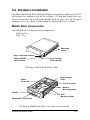
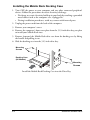
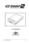
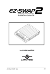
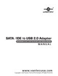
Model: MRK-300FD-BK
Aluminum Mobile Rack
3-1
3-1 Introduction ........................................................................ 3-3
Mobile Rack Features ................................................... 3-3
Unpacking Your Mobile Rack ........................................ 3-4
IDE Basics .................................................................... 3-4
3-2 Hardware Installation.......................................................... 3-5
Mobile Rack Components ............................................. 3-5
Installing the Mobile Rack Docking Case ....................... 3-6
Mounting a Drive in the Drive Case ................................ 3-7
3-3 Using the Mobile Rack ..................................................... 3-10
3-4 Troubleshooting ............................................................... 3-11
3-5 Warranty .......................................................................... 3-11
3-2
Aluminum Mobile Rack
3-1 Introduction
Vantec introduces the EZ-Swap 2 – the convenience of a mobile rack with
cooling abilities on par with most dedicated hard drive coolers. The EZ-Swap 2
features front and rear fans to cool the hard drive from all around. It also
features a keyed lock to prevent accidental removal while in use. The EZ-Swap 2
is compatible with all IDE hard drives and has a sleek, professional look.
EZ-Swap 2 Features
• Aluminum case design aides in heat dissipation
• Two fans circulate and exhaust high heat generated by high-speed drives to
maintain a safe operating temperature environment
• Support high-speed 80-pin UDMA-66/100 Ultra IDE drives
• Drive bay module for mounting a 1.0-inch height, 3.5-inch or 2.5-inch device
in a 5.25-inch drive bay
• Supports fixed 3.5-inch hard disk drives
• Convenient pull-out handle
• Safety lock feature
• LED indicators for power and drive activity
• Two built-in cooling fans
• Fully compatible with MS-DOS, Windows 3.11/95/98/NT, OS/2 Warp
• Dimensions: 8.4" (D) x 5.8" (W) x 1.6" (H)
Aluminum Mobile Rack
3-3
Unpacking Your Mobile Rack
Before installing the Mobile Rack, verify that the following items are included in the
carton. If any parts are damaged or missing, please contact your local dealer or sales
representative immediately.
1.One Mobile Rack Removable Docking Module
2.Twelve (12) mounting screws
3.2 keys
4.One user’s guide
IDE Basics
IDE is an acronym for Integrated Device (Drive) Electronics and is sometimes referred
to as an ATA (AT Attachment) interface. It is the most commonly used interface for
hard disk drives installed on personal computers. Other devices like CD-ROM, tape,
optical drives, and so on have adapted a variation called ATAPI (ATA Packet Interface) and can be intermixed with standard IDE drives because they use the same
cabling and electrical interface.
Most systems today have two IDE channel connectors that are typically referred to as
primary and secondary ports. Each IDE port can have a maximum of two devices that
must be uniquely identified, typically by the setting of a jumper as a ‘master’ or ‘slave’
device.
3-4
Aluminum Mobile Rack
3-2 Hardware Installation
The Aluminum Mobile Rack Docking Module is designed to install in any PC/AT
or Pentium-class computer that has an available 5.25-inch half-height drive bay.
General instructions for installing the Mobile Rack are given since the design of
computer cases varies. Refer to your computer’s manual whenever in doubt.
Mobile Rack Components
The Mobile Rack is comprised of two components:
Docking Case
Drive Case
Mounting
Holes
Key-Lock/Power Switch
Power ON/OFF
LED Indicator
Drive Activity
LED Indicator
EZ-Swap 2 Mobile Rack Drive Caddy
Power
Connector
Data Interface
Cable
Fan Connector
Bottom
Mounting Holes
Handle
Removable Front Panel
Side
Mounting Holes
EZ-Swap 2 Mobile Rack Drive Case (with cover removed)
Aluminum Mobile Rack
3-5
Installing the Mobile Rack Docking Case
1. Turn OFF the power to your computer and any other connected peripheral
devices. Follow the precautions for static electricity discharge:
• Discharge any static electricity build up in your body by touching a grounded
metal surface such as the computer case, if plugged in.
• During installation procedures, avoid any contact with internal parts.
2. Unplug the power cord from the back of the computer.
3. Remove your computer’s cover.
4. Remove the computer’s front cover plate from the 5.25-inch drive bay you plan
to install your Mobile Rack into.
5. Remove (separate) the Mobile Rack drive case from the docking case by lifting
the handle and pulling it out.
6. Slide the docking case into the 5.25-inch drive bay.
Mounting
Screws
Docking Case
(All Models)
Mounting
Screws
Install the Mobile Rack Docking Case into the Drive Bay
3-6
Aluminum Mobile Rack
7. Position the docking case so its mounting holes align with the drive bay’s
mounting holes. Secure with the supplied mounting screws (two/four on
each side.)
8. Attach an existing IDE 40-pin data cable from the system motherboard (or
IDE controller card) to the 40-pin connectors on the back of the docking
case.
Most connectors are keyed for proper insertion. If there is no key, orient the
cable so the pin-1 colored stripe edge is closest to the power connector.
9. Connect an available 4-pin power cable from the system’s power supply to
the 4-pin connector on the back of the docking case. The power connector is
‘D’ shaped to ensure proper orientation when making the connection.
Pin 1
40-pin IDE Connector,
Power Connector
Docking Module Data Cable and Power Connectors
10. Replace the computer’s cover and reconnect the power and other external
cabling.
Mounting a Drive in the Drive Case
Proceed with the following steps to install a 3.5-inch drive device in the Mobile Rack
drive case. (Note: a special adapter kit is required in order to install a 2.5-inch drive.)
1.Remove the Mobile Rack drive case cover by removing the two mounting screws,
then sliding the cover towards the back of the unit.
Slide Cover Off
Mounting
Screws (x2)
Remove the Drive Case Cover
Aluminum Mobile Rack
3-7
c. Unscrew the fan’s two mounting screws and remove the fan.
Remove Fan
Fan Mounting
Screws
IMPORTANT
3. If you are installing a new hard drive into the Mobile Rack, you may need to
configure the drive before you install it.
Refer to the drive manufacturer’s documentation and
For IDE drives:
configure the drive as ‘Master’, ‘Cable Select’, or ‘Slave’ depending on the
configuration of your computer. After you complete this installation, you may
also need to re-configure the computer’s BIOS Setup to make the drive functional
4. Connect the cables from the Mobile Rack drive case to the appropriate pin
connectors of the drive.
For IDE models: The drive case’s 40-/80-pin IDE cable supports 3.5-inch
drives. Attach the power and IDE cables from the Mobile Rack drive case to the
drive. The power connector is ‘D’ shaped to correctly orient the connector.
The colored stripe on the IDE cable should be closest to the power connector.
3-8
Aluminum Mobile Rack
5. Carefully position the drive inside the drive case.
6. Secure the drive in place using the supplied mounting screws. Use the mounting
holes on the sides or bottom, depending on the design of the drive.
Power Cable
Mounting
Screws
Colored Stripe
Data Cable
Mounting
Screws
Install the Drive in Drive Case
7. Slide the drive case cover back on and secure with the two mounting screws.
Mounting
Screws (x2)
Mobile Rack Drive Case Ready for Use
Aluminum Mobile Rack
3-9
3-3 Using the Mobile Rack
WARNING
• DO NOT remove the drive case while the drive is working.
Damage to data may result.
• The Key-Lock must be in the Lock position while in use.
To insert the Mobile Rack drive case:
1. Insert the Mobile Rack drive case (with drive installed) into the installed Mobile
Rack docking case and push firmly until the drive is seated.
2. Insert the key and turn it right to lock. The LED on the Mobile Rack should
light after a slight delay. The installed Mobile Rack device is ready to use.
Key-Lock in
Lock Position
To remove the Mobile Rack drive case:
1. Insert the key and turn it left to unlock. Note that the power LED on the
Mobile Rack should now be OFF.
2. Gently pull on the Mobile Rack handle to slide the drive case out.
Key-Lock in
Unlock Position
3-10
Aluminum Mobile Rack
3-4 Troubleshooting
Q. I installed the EZ-Swap 2 but my computer does not detect the hard drive in it.
A. Be sure to turn on the EZ-Swap 2 by setting the Key-Lock in the Lock position. The
EZ-Swap 2 will not turn on unless it is locked. If you are using a brand new drive, make
sure you initialize, partition and format the drive before trying to use it. This can be done
using the software that comes with the HARD DRIVE or by using Windows’ Disk
Management utility.
Q. The data on my hard drive is corrupt!
A. Connecting your hard drive to the EZ-Swap 2 is just like connecting a your hard
drive to the inside of your computer. The EZ-Swap 2 itself will not corrupt your data.
If your data has become corrupt, it is likely caused by removal of the EZ-Swap 2 cartridge
while data was still being written to the hard drive.
NEVER REMOVE THE EZ-SWAP 2 CARTRIDGE WHILE DATA IS BEING
WRITTEN TO THE HARD DRIVE. Doing may cause the hard drive to become
corrupt. Make sure all applications being run off the disk and all files in use are no
longer in use before removing the disk. To be safe, it would be best to shut down your
system before removing the cartridge.
For more help, please visit www.vantecusa.com and check the TECH
SUPPORT section.
3-5 Warranty
The EZ-Swap 2 comes with a 3 year limited warranty (90 day parts). If your unit
should become defective within that time frame, please go to www.vantecusa.com
for information on how to receive warranty replacement. Cosmetic defects and
missing parts are not covered under this warranty. Please check the contents of the
unit to make sure you received all parts. Also, check for any cosmetic flaws. If any
parts are missing or if there are cosmetic defects, please contact the retailer from which
you purchased the unit and ask for a replacement.
Aluminum Mobile Rack
3-11