1
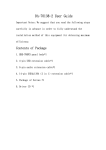
Manual
3.5" Multi Front Panel + Cardreader 50plus
english
www.equip-info.net
Manual_Page 2
Important Note:
We suggest that you read the following steps carefully in advance in order to fully understand the installation method of this equipment for obtaining maximum efficiency.
Package Contents
1. 3.5” Multi Front Panel
2. Setup CD
3. Slot bracket
4. Octopus cable for FireWire, USB and SATA connection
5. SATA connection cable
6. Y-cable with 2x audio plug
7. USB connection cable
8. Set of screws
Driver and Hardware Installation
For Windows Vista/XP/2000/ME system, drivers are all provided by the operating
systems, no additional driver needed. The card reader will be recognized by OS
automatically once it is connected.
Driver Installation for Windows 98
Follow the installation guide below to complete the driver installation.
1. Insert Setup CD, and double click “AM-Reader-98Drv-Setup”
2. Click “Next” on the welcome page of “InstallShield Wizard”
3. Click “finish” to complete the installation
You will see four removable disk icons of the all-in-1 card reader on the explorer window
once you connect your card reader to the PC. The disk drive letters are determined by the
PC’s configuration which may varies.
Note: The driver installation above is designed for Windows 98 only.
www.equip-info.net
Manual_Page 3
Driver Installation for Mac OS 9.x
1. Decompress driver binary file in your CD, it will create two driver files in
specific directory.
2. Copy these two files into Mac OS 9.x system extension directory.
3. Reboot your system.
4. Plug your card reader on USB, and use it.
Picture 1
Hardware Installation
Please connect the cables to the panel body as shown in picture 1.
There are three cables need to be connected to the panel body.
The white 4-pin connector on the left should connect with the 4-pin connector
of the USB connection cable (
attention: this connector has been particularly
designed and can be connected only in the proper way).
The 16-pin connector in the middle should connect with the 16-pin connector of
the 0ctopus cable for FireWire, USB and SATA connection (
attention: the side
with a key should be connected upwards, as shown in the picture 2).
The left 5-pin connector should connect with the 5-pin connector of the Y-cable
with 2x audio plug (
Picture 2
attention: this connector has been particularly designed
and can be connected only in the proper way).
The red SATA cable is already fixed on the panel body.
Fixing the Panel Body:
Now the wire connection of the whole set is completed, slide the extension cables
and the panel body into any open external 3.5” disk driver slot, and use the
enclosed screws to fasten it.
Connect extension ports to the correspondent ports.
1. Connect the USB, FireWire1394a and audio extension ports as shown in picture 3
(audio extension ports should connect to the audio-in ports (MIC & SPK) located
on the back side according to their colors)
www.equip-info.net
Picture 3
Manual_Page 4
2. Connect the two SATA connectors to the correspondent ports on the motherboard
as shown in picture 4 (
attention: these connectors have been particularly
designed and can be connected only in the proper way).
Finish hardware installation:
Please check that all cables/connections are fixed properly and turn on the
computer, the power LED of the front panel shall be on.
www.equip-info.net
Picture 4