1
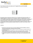
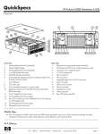
2.5 SATA External HDD Enclosure w/
3.5/5.25 Front Drive Bay
SAT2510U2REM
*actual product may vary from photos
DE: Bedienungsanleitung - de.startech.com
FR: Guide de l'utilisateur - fr.startech.com
ES: Guía del usuario - es.startech.com
IT: Guida per l'uso - it.startech.com
NL: Gebruiksaanwijzing - nl.startech.com
PT: Guia do usuário - pt.startech.com
For the most up-to-date information, please visit: www.startech.com
Manual Revision: 10/28/2011
FCC Compliance Statement
This equipment has been tested and found to comply with the limits for a Class B digital
device, pursuant to part 15 of the FCC Rules. These limits are designed to provide reasonable
protection against harmful interference in a residential installation. This equipment generates,
uses and can radiate radio frequency energy and, if not installed and used in accordance with
the instructions, may cause harmful interference to radio communications. However, there
is no guarantee that interference will not occur in a particular installation. If this equipment
does cause harmful interference to radio or television reception, which can be determined by
turning the equipment off and on, the user is encouraged to try to correct the interference by
one or more of the following measures:
• Reorient or relocate the receiving antenna.
• Increase the separation between the equipment and receiver.
• Connect the equipment into an outlet on a circuit different from that to which the receiver
is connected.
• Consult the dealer or an experienced radio/TV technician for help.
Use of Trademarks, Registered Trademarks, and other Protected Names and
Symbols
This manual may make reference to trademarks, registered trademarks, and other
protected names and/or symbols of third-party companies not related in any way to
StarTech.com. Where they occur these references are for illustrative purposes only and do not
represent an endorsement of a product or service by StarTech.com, or an endorsement of the
product(s) to which this manual applies by the third-party company in question. Regardless
of any direct acknowledgement elsewhere in the body of this document, StarTech.com hereby
acknowledges that all trademarks, registered trademarks, service marks, and other protected
names and/or symbols contained in this manual and related documents are the property of
their respective holders.
Instruction Manual
Table of Contents
Introduction ............................................................................................1
Features......................................................................................................................................................... 1
Package Contents...................................................................................................................................... 1
System Requirements............................................................................................................................... 1
Installation...............................................................................................2
Installing the hard drive in the drive enclosure.............................................................................. 3
Installing the drive bay in the computer........................................................................................... 4
Connecting the Drive Enclosure - Removable storage................................................................ 5
Removing the Drive Enclosure - Removable storage................................................................... 5
Connecting the Drive Enclosure - Standalone................................................................................ 6
Removing the Drive Enclosure - Standalone................................................................................... 6
Specifications...........................................................................................7
Technical Support...................................................................................8
Warranty Information.............................................................................8
Instruction Manual
i
Introduction
Thank you for purchasing a StarTech.com 3.5” Bay Removable 2.5” SATA Drive
Enclosure. This product offers versatile functionality, acting as either an internal
desktop removable drive enclosure, or an external drive enclosure. Ideal for entry-level
servers, network attached storage systems or applications requiring data transport
from one location to another, SAT2510U2REM is the perfect solution for data mobility.
Features
• Hot swappable plug and play operation
• Easy add-on storage for home or office usage
• Desktop application - Insert & Remove 2.5” drive enclosure with SATA hard drive at
the push of a button
• Portable (External) application - Instantly connect the enclosure to a host computer
or notebook as external storage, via USB 2.0 connection
Package Contents
•
•
•
•
•
•
•
•
•
2.5” SATA hard drive enclosure
3.5” Drive bay
5.25” Drive bracket
USB 2.0 Cable
SATA cable
5V DC Cable
4 pin power cable
Users Manual
Screw Kit
System Requirements
• (Internal use) Any computer with available 5.25” drive bay & SATA motherboard
connection
• (External use) Any desktop or notebook with an available USB port
Instruction Manual
1
Installation
Drive Bay
Drive Enclosure
Drive Bay Bracket
WARNING: Hard drives require careful handling, especially when being transported. If
you are not careful with your hard disk, lost data may result. Always handle your hard
drive and storage device with caution.
WARNING: Hard drives, like all computer equipment can also be severely damaged
by static electricity. Be sure that you are properly grounded before opening your
computer case or touching any components. StarTech.com recommends that you
wear an anti-static strap when installing any computer equipment. If an antistatic strap
is unavailable, discharge yourself of any static electricity build-up by touching a large
grounded metal surface (such as the computer case) for several seconds.
WARNING: Do not disconnect any cables or power sources while the hard drive is
active. This can result in data loss and possible damage to the hard drive.
Instruction Manual
2
Installing the hard drive in the drive enclosure
1. Remove the two screws from the rear panel of the Drive Enclosure. Remove the rear
panel of the Drive Enclosure.
2. Remove the circuit board from the drive enclosure.
3. Attach the 2.5” SATA hard drive to the circuit board, and fasten it to the board using
drive mounting screws.
4. Once the hard drive has been secured on the circuit board, replace the circuit board
(with hard drive attached) in the drive enclosure. Fasten the rear panel of the drive
enclosure to the enclosure, using the screws that were removed in step #1.
Instruction Manual
3
Installing the drive bay in the computer
Please note that the SAT2510U2REM drive bay can be installed into either a 3.5” or a
5.25” drive bay slot on the host computer, using the included 5.25” Drive Bay Bracket.
If you wish to install the Drive Bay directly into the drive bay slot provided by the host
computer, please skip steps 1 and 2 in the instructions that follow:
1. Insert the Drive Bay into the 5.25” bracket provided, ensuring that the holes located
on the sides of the drive bay are aligned with the holes in the sides of the bracket.
Ensure Proper Alignment
2. Fasten the Drive Bay to the Bracket, using the screws provided. To ensure proper
attachment to the Bracket, secure the Drive Bay to the Bracket both on the sides and
on the bottom of the Bracket.
3. Power down the computer.
4. Remove the cover of the host computer drive bay slot into which you wish to install
the Drive Bay and Enclosure, as well as the side panels of the computer case. If you
require further instruction on this step, please consult the documentation that
accompanied your computer or computer case at the time of purchase.
5. Insert the Drive Bay into an available 3.5” or 5.25” drive bay slot as appropriate,
through the opening at the front of the case provided following step 3. Please
ensure proper alignment of screw holes in the Drive Bay and drive bay slot.
6. Secure the Drive Bay to the drive bay slot, using the screws provided. To ensure
proper attachment to the drive bay slot, secure the Drive Bay to the drive bay slot on
both sides of the bay slot.
7. Connect an available LP4 (4 pin) power connector (provided by computer power
supply) to the 4 pin power connector, located on the rear panel of the Drive Bay.
Instruction Manual
4
8. Connect one end of the SATA cable provided to the SATA port located on the rear
panel of the Drive Bay. Connect the remaining end of the SATA cable to an available
SATA connector as provided by the computer motherboard.
9. Once the Drive Bay has been installed in the computer, replace the side panels of
the computer casing (removed in step 3).
Connecting the Drive Enclosure - Removable storage
Once the Drive Bay has been installed in the computer, you can use the Drive Enclosure
as ejectable (removable) storage. Please note that when inserting or removing the
Drive Enclosure, the computer must be powered down in order to avoid data loss or
damage to the drive.
1. Power down the host computer
2. Insert the Drive Enclosure into the Drive Bay. The Eject button will pop out,
indicating that the Drive Enclosure is firmly connected.
3. Restore power to the computer. Once the operating system is fully loaded and has
detected the presence of the drive, any necessary software will install automatically,
4. Restore power to the computer. If you are using a Windows operating system, any
necessary software will install automatically, once the operating system is fully
loaded and has detected the presence of the drive,
5. The drive is now ready for use and will be available in My Computer, designated
(typically) with a drive letter subsequent to those assigned to stationary
(permanent) hard drives.
Removing the Drive Enclosure - Removable storage
To remove the Drive Enclosure from the host computer when inserted in the Drive Bay:
1. Power down the host computer
2. Press the eject button located next to the drive bay insertion slot
3. Remove the drive enclosure from the bay
4. Restore power to the computer
Instruction Manual
5
Connecting the Drive Enclosure - Standalone
To connect the Drive Enclosure to the host computer, for use as standalone storage:
1. Insert the small connector (USB Mini-B) into the USB Mini-B port located on the rear
panel of the Drive Enclosure. Insert the remaining end (USB type A) connector into
an available USB port on the host computer.
2. Insert the cylindrical connector provided by the power adapter into the power port
on the rear panel of the Drive Enclosure. Connect the remaining end of the power
adapter to an available power outlet.
3. Once the Drive Enclosure is connected via USB and powered, the drive will be
accessible to the host computer. If you are using a Windows operating system,
please wait a few moments, to allow the operating system to automatically install
the necessary files; once the files have successfully installed, the drive will be
available in My Computer, designated (typically) with a drive letter subsequent to
those assigned to stationary (permanent) hard drives.
Removing the Drive Enclosure - Standalone
When connected to the host computer as standalone storage, you will not need to
power down the computer in order to remove the drive enclosure. Please note that
removing the drive while in operation may cause data loss or damage to the drive. To
avoid this, please use the Safely Remove Hardware wizard, which is prompted by
clicking on the wizard icon located near the clock in the bottom right corner (typically)
of the Windows desktop.
Safely Remove Hardware
To remove the Drive Enclosure from the host computer:
1. Remove the USB connection between the Drive Enclosure and the computer.
2. Remove the power adapter from the Drive Enclosure.
Instruction Manual
6
Specifications
Internal Mount: 5.25” drive bay or 3.5”
drive bay
Form Factor
3.5” Internal Bay:
External to Host - 4 pin power input 7
pin SATA
Internal to HD enclosure - 7 pin and 15
pin SATA
2.5” HD Enclosure:
External ports - USB 2.0 mini B
DC 5V power to USB
Internal - 7 pin and 15 pin SATA
Connectors
Power Adapter
External Use - 5V DC to USB 2.0
SATA to SATA
USB Mini B to USB Type A
4 pin power to LP4
5V DC to USB 2.0
Cables
Internal data transfer rate: up to 1.5Gb/s
External use: Up to 480Mbps (USB)
Maximum Data Transfer Rate
Regulatory Certifications
FCC, CE, RoHS
Chipset
JMicron 20336
Windows / 2000 / XP / Vista / 7 /
MAC OS 9.x or higher
Linux 2.4.1.0 or above
OS Support
2.5” Enclosure - 131 x 77 x 14mm
(LxWxH)
3.5” Bay - 15 x 100 x 25mm
(LxWxH)
5.25” Bracket - 138 x 144 x 40mm
(LxWxH)
Dimensions
Weight
Instruction Manual
0.5 kg
7
Technical Support
StarTech.com’s lifetime technical support is an integral part of our commitment to
provide industry-leading solutions. If you ever need help with your product, visit
www.startech.com/support and access our comprehensive selection of online tools,
documentation, and downloads.
For the latest drivers/software, please visit www.startech.com/downloads
Warranty Information
This product is backed by a two year warranty.
In addition, StarTech.com warrants its products against defects in materials
and workmanship for the periods noted, following the initial date of purchase.
During this period, the products may be returned for repair, or replacement with
equivalent products at our discretion. The warranty covers parts and labor costs only.
StarTech.com does not warrant its products from defects or damages arising from
misuse, abuse, alteration, or normal wear and tear.
Limitation of Liability
In no event shall the liability of StarTech.com Ltd. and StarTech.com USA LLP (or their
officers, directors, employees or agents) for any damages (whether direct or indirect,
special, punitive, incidental, consequential, or otherwise), loss of profits, loss of business,
or any pecuniary loss, arising out of or related to the use of the product exceed the
actual price paid for the product. Some states do not allow the exclusion or limitation
of incidental or consequential damages. If such laws apply, the limitations or exclusions
contained in this statement may not apply to you.
Instruction Manual
8
Hard-to-find made easy. At StarTech.com, that isn’t a slogan. It’s a promise.
StarTech.com is your one-stop source for every connectivity part you need. From
the latest technology to legacy products — and all the parts that bridge the old and
new — we can help you find the parts that connect your solutions.
We make it easy to locate the parts, and we quickly deliver them wherever they need
to go. Just talk to one of our tech advisors or visit our website. You’ll be connected to
the products you need in no time.
Visit www.startech.com for complete information on all StarTech.com products and
to access exclusive resources and time-saving tools.
StarTech.com is an ISO 9001 Registered manufacturer of connectivity and technology
parts. StarTech.com was founded in 1985 and has operations in the United States,
Canada, the United Kingdom and Taiwan servicing a worldwide market.