1
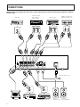
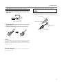
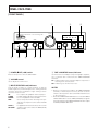
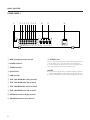
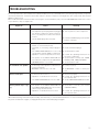
STEREO AMPLIFIER
A-109
Operating Instructions
1
Thank you for buying this PIONEER product.
Please read through these operating instructions so you will
know how to operate your model properly. After you have
finished reading the instructions, put them away in a safe
place for future reference.
In some countries or regions, the shape of the power plug and
power outlet may sometimes differ from that shown in the
explanatory drawings. However, the method of connecting
and operating the unit is the same.
WARNING: TO PREVENT FIRE OR SHOCK HAZARD,
DO NOT EXPOSE THIS APPLIANCE TO RAIN OR MOISTURE.
This product complies with the Low Voltage Directive (73/
23/EEC), EMC Directives (89/336/EEC, 92/31/EEC) and CE
Marking Directive (93/68/EEC).
IMPORTANT
CAUTION
RISK OF ELECTRIC SHOCK
DO NOT OPEN
The lightning flash with arrowhead symbol, within an
equilateral triangle, is intended to alert the user to the
presence of uninsulated "dangerous voltage" within the
product's enclosure that may be of sufficient magnitude
to constitute a risk of electric shock to persons.
IMPORTANT
FOR USE IN THE UNITED
KINGDOM
The wires in this mains lead are coloured in
accordance with the following code :
Blue
: Neutral
Brown
: Live
If the plug provided is unsuitable for your socket
outlets, the plug must be cut off and a suitable plug
fitted.
CAUTION:
TO PREVENT THE RISK OF ELECTRIC SHOCK, DO NOT
REMOVE COVER (OR BACK). NO USER-SERVICEABLE
PARTS INSIDE. REFER SERVICING TO QUALIFIED
SERVICE PERSONNEL.
The cut-off plug should be disposed of and must not be
inserted into any 13 amp socket as this can result in electric
shock. The plug or adapter or the distribution panel should
be provided with a 5 amp fuse. As the colours of the wires
in the mains lead of this appliance may not correspond with
the coloured markings identifying the terminals in your plug,
proceed as follows :
The wire which is coloured blue must be connected to the
terminal which is marked with the letter N or coloured black.
The wire which is coloured brown must be connected
to the terminal which is marked with the letter L or coloured
red.
The exclamation point within an equilateral triangle is
intended to alert the user to the presence of important
operating and maintenance (servicing) instructions in the
literature accompanying the appliance.
Do not connect either wire to the earth terminal of a
three-pin plug.
NOTE
After replacing or changing a fuse, the fuse cover in the
plug must be replaced with a fuse cover which corresponds to the colour of the insert in the base of the plug
or the word that is embossed on the base of the plug, and
the appliance must not be used without a fuse cover. If
lost, replacement fuse covers can be obtained from your
dealer.
Only 5 A fuses approved by B.S.I. or A.S.T.A to B.S.
1362 should be used.
POWER-CORD CAUTION
MAINTENANCE OF EXTERNAL SURFACES
Handle the power cord by the plug. Do not pull out the plug by
tugging the cord and never touch the power cord when your
hands are wet as this could cause a short circuit or electric
shock. Do not place the unit, a piece of furniture, etc., on the
power cord, or pinch the cord. Never make a knot in the cord
or tie it with other cords. The power cords should be routed
such that they are not likely to be stepped on. A damaged
power cord can cause fire or give you an electrical shock.
Check the power cord once in a while. When you find it
damaged, ask your nearest PIONEER authorized service
center or your dealer for a replacement.
÷ Use a polishing cloth or dry cloth to wipe off dust and
dirt.
÷ When the surfaces are very dirty, wipe with a soft cloth
dipped in some neutral cleanser diluted five or six times
with water, and wrung out well, and then wipe again
with a dry cloth. Do not use furniture wax or cleaners.
÷ Never use thinners, benzine, insecticide sprays or other
chemicals on or near this unit, since these will corrode
the surfaces.
2
CONTENTS
FEATURES ......................................................................... 3
OPERATIONS ..................................................................... 9
INSTALLATION .................................................................. 3
TROUBLESHOOTING ...................................................... 11
CONNECTIONS .................................................................. 4
SPECIFICATIONS ............................................................. 12
PANEL FACILITIES ............................................................. 6
FEATURES
7 Advanced Direct Energy MOS Power Amp
Pioneer incorporates highest quality amp circuitry featuring Advanced Direct Energy MOS FET devices which can
achieve higher performance. Together with Pioneer’s original Wide Range Linear Circuit technology they reduce
power consumption while maintaining the power output of
current models.
In terms of performance, this technology contributes to flat
damping factor characteristics across the audio spectrum.
It also allows a wide range and especially ultra␣ high frequencies to be reproduced more accurately and improves
power linearity.
7 High-power Output of 40 W+40 W/8 Ω(DIN)
7 Wide-Range Linear Circuit
This new current feedback circuit assures improved operating stability for flat output impedance and stable driving
of speakers across the full range of frequencies.
7 Low power consumption design.
7 Complementary capacitor pair.
7 Stabilizer
Transformer stabilizer and stabilizer frame (attached to
chassis) deliver powerful sound.
INSTALLATION
LOCATION
Install the unit in a well-ventilated location where it
will not be exposed to high temperatures or humidity.
Do not install the unit in a location which is exposed to direct
rays of the sun, or near hot appliances or radiators. Excessive
heat can adversely affect the cabinet and internal components. Installation of the unit in a damp or dusty environment
may also result in a malfunction or an accident. (Avoid
installation near cookers etc., where the unit may be exposed
to oily smoke, steam or heat.)
Do not install the unit on a tottered stand, nor on an unstable
or inclined surface.
VENTILATION
÷ When installing this unit, make sure to leave space around
the unit for ventilation to improve heat radiation (at least 60
cm at top, 10 cm at rear, and 30 cm at each side). If not
enough space is provided between the unit and walls or
other equipment, heat will build up inside, interfering with
performance or causing malfunctions.
÷ Do not place on a thick carpet, bed, sofa or fabric having a
thick pile. Do not cover with fabric or other covering.
Anything that blocks ventilation will cause internal temperature to rise, which may lead to breakdown or fire
hazard.
3
CONNECTIONS
Before making or changing the connections, switch off the power switch and disconnect the power cord from
the AC outlet.
Cassette deck/
CD recorder/
MD recorder
CD player
Adaptor component
(graphic equalizer etc.)
Cassette deck
MINIDISC
CD
IN
L
R
PLAY
REC
PLAY
REC
OUT
L
L
R
R
L
L
L
R
R
R
L
L
R
L
R
L
R
L
L
R
R
OUT
L
R
R
R
L
L
L
R
R
SPEAKERS
SIGNAL
GND
PHONO
TUNER
CD
LINE
TAPE 1/CD-R/MD
REC
TAPE 2 MONITOR
PLAY
REC
R
PLAY
L
L
AC INLET
L
R
R
IN
IN
IN
IN
OUT
IN
OUT
IN
ª
·
·
·
·
ª
L
R
L
L
R
R
ª
ª
To an AC wall socket.
L
L
R
R
L
R
OUT
FM-AM
Turntable
4
Tuner
L
R
AUDIO OUT
DVD
DVD player, VCR, etc.
Speaker
system (Left)
Speaker
system (Right)
CONNECTIONS
CONNECTING THE SPEAKER CORDS
1. Strip off the vinyl covering and twist the tip of the
wire core.
10mm
CONNECTING THE INPUT/OUTPUT
CORDS
Connect the white plug to the L (left) channel, and the red plug
to the R (right) channel. Be sure to push the plugs securely.
Left channel
2. Loosen the knob and insert the wire core into the
terminal hole.
3. Tighten the knob to fix the wire core in place.
2
1
L
White plug
Twist the wire core
R
Right channel
Red plug
\
3
NOTE:
Do not allow any of the cord conductors to protrude from the
terminals or touch any other conductors. Malfunctioning or
breakdowns may occur when conductors come into contact
with each other.
Speaker Impedance
The speaker systems used should have a rated impedance in
the range of 6 - 16 Ω.
5
PANEL FACILITIES
[ FRONT PANEL ]
1
2
STEREO AMPLIFIER
3
4
VOLUME
z¿,?/ Direct Energy MOS
CD
TUNER
PHONO
LINE
TAPE 1/
CD-R/MD
TAPE 2
MONITOR
POWER
— OFF _ ON
BASS
SPEAKERS
TREBLE
BALANCE
PHONES
LOUDNESS
–
-
0
+
9
–
+
8
DIRECT
MIN
7
TAPE 2
MONITOR
L
MAX
6
INPUT SELECTOR
R
5
1 POWER (—OFF/_ON) switch
4 TAPE 2 MONITOR button/indicator
Press to turn power to the unit ON and OFF.
Use when there is an adaptor component (graphic equalizer,
etc.) or cassette deck connected to the TAPE2 MONITOR
terminals.
On : Indicator lights when using the adaptor component or
listening to the cassette deck.
Off : Indicator goes off when not in use.
2 VOLUME control
Use to adjust the volume level.
3 INPUT SELECTOR knob/indicators
Turn the knob clockwise or counterclockwise so that the
indicator lights for your desired input source. Turning the knob
clockwise causes the lit indicator to right. Turning counterclockwise causes it to left.
CD
: For compact disc playback with a CD player.
TUNER
: For AM or FM broadcast reception with a tuner.
PHONO
: For record playback with a turntable.
LINE
: Set to this position when listening to the program from a component connected to the LINE
terminals.
TAPE 1/
: For playback with a cassette deck, CD recorder
CD-R/MD
or MD recorder connected to the TAPE1/CD-R/
MD terminals.
6
NOTES:
• When no connections are made to the TAPE2 MONITOR
terminals, or when they are not in use, be sure to set this
switch to the off position. (No sound will be heard if it is set
to the on position.)
• When the TAPE2 MONITOR indicator is on and the INPUT
SELECTOR knob is not set to TAPE1/CD-R/MD, the signals
which are input through TAPE2 MONITOR are then output
at TAPE1/CD-R/MD REC OUT.
PANEL FACILITIES
5 BALANCE control
8 TREBLE tone control
Should normally be left in the center position. Adjust balance
if the sound is louder from one of the speakers. If the right side
is louder, turn toward the L (left) position and if the left side is
louder, turn toward the R (right) position.
Use to adjust the high-frequency tone. The center position is
the flat (normal) position. When turned to the right, highfrequency tones are emphasized; when turned to the left,
high-frequency tones are de-emphasized.
NOTE:
NOTE:
This control does not operate when the DIRECT button is in
the on position.
This control does not operate when the DIRECT button is in
the on position.
6 DIRECT button/indicator
9 BASS tone control
Use this button when you do not wish to pass the output from
input terminal equipment through the various frequency adjusting circuits (BASS, TREBLE, BALANCE, LOUDNESS).
On : The indicator lights: The signals passing through the
input terminals are reproduced without passing through
the various frequency adjusting circuits. This results in
flat, pure sound which is a more faithful reproduction of
the input source.
Off : The indicator goes off: The signal passes through the
various frequency adjusting circuits.
Use to adjust the low-frequency tone. The center position is
the flat (normal) position. When turned to the right, lowfrequency tones are emphasized; when turned to the left,
low-frequency tones are de-emphasized.
7 LOUDNESS button/indicator
Use when listening at low volume levels.
On : The indicator lights: Boosts low and high frequencies to
give added punch to playback even at a low volume
level.
Off : The indicator goes off: Should normally be left in this
position.
NOTE:
This button does not operate when the DIRECT button is in
the on position.
NOTE:
This control does not operate when the DIRECT button is in
the on position.
0 PHONES jack
When using headphones, insert the plug into this jack.
NOTE:
The speakers continue to output sound even when headphones are plugged into this jack.
To mute the sound from the speakers, press the SPEAKERS
button to OFF.
- SPEAKERS button/indicator
Use this button to listen to the speaker system connected to
the SPEAKERS terminals.
On : The indicator lights. Sound is heard from the speaker
system.
Off : The indicator goes off. No sound is heard from the
speaker system. Set to this position when listening with
headphones.
7
PANEL FACILITIES
[ REAR PANEL ]
1
23456789
0
-
=
L
AC INLET
SPEAKERS
SIGNAL
GND
PHONO
TUNER
CD
LINE
TAPE 1/CD-R/MD
REC
PLAY
TAPE 2 MONITOR
REC
R
PLAY
L
L
R
R
IN
IN
IN
IN
OUT
IN
OUT
IN
ª
·
·
ª
1 GND (Turntable ground) terminal
= AC INLET jack
2 PHONO terminals
Connect one end of the power cord to here and the other end
to an AC wall socket, or the AC outlet of an audio timer.
If you are going to be away from home for a long period of
time, disconnect the unit from the wall socket.
3 TUNER terminals
4 CD terminals
5 LINE terminals
6 TAPE 1/CD-R/MD REC (OUT) terminals
7 TAPE 1/CD-R/MD PLAY (IN) terminals
8 TAPE 2 MONITOR REC (OUT) terminals
9 TAPE 2 MONITOR PLAY (IN) terminals
0 SPEAKERS terminals (Right channel)
- SPEAKERS terminals (Left channel)
8
NOTES:
÷ If you use an other power cord than provided, we cannot
assume the liabilities in what may occur as a result of it.
÷ (The provided power cord has a current capacity of 2.5 A.)
OPERATIONS
BEFORE BEGINNING OPERATIONS
1.
2.
3.
4.
5.
6.
Set the VOLUME control to minimum.
Set the POWER switch to ON.
Press the SPEAKERS switch to ON.
Set the BALANCE control to the center position.
Set the DIRECT button to off.
Set the TAPE2 MONITOR button to off.
PLAYBACK PROCEDURES
1. Set the INPUT SELECTOR knob to the desired
playback source.
÷
÷
÷
÷
For playback of a compact disc: Set to [CD].
For reception of an AM/FM broadcast: Set to [TUNER].
For playback of a record: Set to [PHONO].
For playback with the equipment connected to the LINE
terminals: Set to [LINE].
÷ For playback of a tape: Set to [TAPE1/CD-R/MD].
NOTES:
÷ When you do not want to monitor the TAPE2 MONITOR
sound, set the PATE2 MONITOR button to OFF.
÷ When you select PHONO, the sound is muted for a few
seconds.
2. Operate the equipment to begin playback.
3. Adjust playback volume with the VOLUME control on this unit.
4. Adjust the tone to your preference using the
BASS and TREBLE controls, and LOUDNESS button.
COPYING TAPES
When two decks are used, you can record the sounds from
one deck onto the other.
Application examples:
÷ To make a tape copy with contents identical to the original
tape.
÷ To edit a recording of an FM broadcast in order to cut out
unwanted commercials, recording only of desired material
onto another tape.
1. Load tapes for playback (pre-recorded tape) and
recording (blank tape) into the respective cassette decks.
2. Select the copying direction with the INPUT SELECTOR knob and TAPE2 MONITOR button.
÷ When copying from the cassette deck of the TAPE1/CDR/MD terminals to the cassette deck of the TAPE2
MONITOR terminals: Set the INPUT SELECTOR knob
to TAPE1/CD-R/MD.
÷ When copying from the cassette deck of the TAPE2
MONITOR terminals to the cassette deck of TAPE1/CDR/MD terminals: Set the TAPE2 MONITOR button to
ON and the INPUT SELECTOR knob to a position other
than TAPE1/CD-R/MD.
3. Operate the cassette decks to begin copying.
Set the cassette deck with the original (playback) tape to
the playback mode, and set the cassette deck with the
blank tape to the recording mode.
RECORDING TAPES
1. Select the recording equipment with the INPUT
SELECTOR knob.
2. Begin recording by operating the recording equipment and cassette deck.
Refer to the operating instructions of your cassette deck
for proper operating procedures.
9
OPERATIONS
TO USE THE COMPONENT CONNECTED
TO THE TAPE2 MONITOR TERMINALS
[For a cassette deck]
÷ A cassette deck connected here can be operated in the
same way (recording and playback) as a deck connected to
the TAPE2 MONITOR terminals.
÷ Also, if two decks are used, you can copy tapes from one
deck onto the other (see the section on “COPYING TAPES”).
1. Set the TAPE2 MONITOR button to ON.
2. Operate the cassette deck to perform playback
(or recording).
NOTE:
The source selected with the INPUT SELECTOR knob is
backed up for a few days even when the POWER switch is set
to off or the power cord is unpluged.
After this period, the CD is automatically selected when the
power is supplied.
[For an adaptor component]
By connecting a graphic equalizer, source sounds (from discs,
tapes, AM/FM broadcasts, etc.) can be heard with added
sound and tone compensation.
Sounds compensated with the adaptor component can be
recorded on the cassette deck connected to the TAPE1/CDR/MD terminals.
1. Set the TAPE2 MONITOR button to ON.
2. Play back the source.
3. Operate the adaptor component.
NOTE:
Be sure to perform this operation with the adaptor component
power switch in the on position. Even when not using the
adaptor component, its power switch must be left on. If the
adaptor component is switched off, no sound will be produced, or the playback sound will be distorted.
10
TROUBLESHOOTING
Incorrect operations are often mistaken for trouble and malfunctions. If you think that there is something wrong with this component,
check the points below. Sometimes the trouble may lie in another component. Investigate the other components and electrical
appliances being used.
If the trouble cannot be rectified even after exercising the checks listed below, ask your nearest PIONEER authorized service center
or your dealer to carry out repair work.
Symptom
No power supplied to unit.
No sound.
Cause
÷ Power plug is disconnected from outlet.
÷ The amplifier’s power plug has been plugged
into another component’s power outlet (e.g.
timer, etc.) but power to that unit is disconnected.
÷ The AC INLET plug is disconnected.
÷ Insert plug securely into outlet.
÷ Turn on power to other component.
÷ Connecting cords are disconnected from terminals, or connected incorrectly.
÷ Terminals, or connecting cords pin plugs are
dirty.
÷ The TAPE2 MONITOR button is set to ON
(except when using an adaptor component).
÷ Operation of other components is incorrect.
÷ Connect securely.
÷ The position of the INPUT SELECTOR does
not match the component to be played back.
÷ SPEAKERS button is set to OFF.
No sound from one speaker.
Cannot record tapes.
÷ Insert the AC INLET plug securely till the
bottom of the jack.
÷ Clean terminals and plugs.
÷ Set the button to OFF.
÷ Consult the operating instructions for
the other components.
÷ Set the button correctly (CD, TUNER,
PHONO, LINE, TAPE1/CD-R/MD).
÷ Set the button to ON.
÷ Connecting cords or speaker cords are disconnected on that side.
÷ BALANCE control is set to one side.
÷ Connect securely.
÷ Connections are incorrect.
÷ Operation of cassette deck is incorrect.
÷ Reconnect properly.
÷ Consult the operating instructions for
the cassette deck.
÷ Set the TAPE2 MONITOR button to OFF.
÷ The TAPE2 MONITOR button is set to ON.
Cannot perform tape copying.
Remedy
÷ The position of the INPUT SELECTOR knob
and TAPE2 MONITOR button are incorrect
(when using 2 cassette decks).
÷ Operation of cassette decks is incorrect.
÷ Set BALANCE control to center position.
÷ Set buttons correctly. (See section
COPYING TAPES.)
÷ Consult the operating instructions for
the cassette decks.
Abnormal functioning of this unit may be cased by, static electricity, or other external interference. To restore normal operation, turn
the power off and then on again, or unplug the AC power cord and then plug it in again.
11
SPECIFICATIONS
Amplifier Section
Power Supply/ Miscellaneous
Continuous power output
(both channels driven at 20 Hz to 20 kHz)**
T.H.D. 0.1 %, 8 Ω ..................................... 30 W + 30 W*
DIN Continuous power output
(both channels driven at 1 kHz)
T.H.D. 1.0 %, 8 Ω ....................................... 40 W + 40 W
Total harmonic distortion**
20 Hz to 20 kHz, 15 W, 8 Ω ................................ 0.08 %*
÷ The above values are applicable when AC 230 V power is
supplied.
Input sensitivity/ impedance
PHONO (MM) ........................................... 2.8 mV/ 50 kΩ
CD, TUNER, LINE, TAPE1/CD-R/MD, TAPE2 MONITOR
................................................................. 200 mV/ 50 kΩ
PHONO (MM) overload level
1 kHz, T.H.D. 0.1 % ............................................. 150 mV
Output level/ impedance
TAPE1 REC, TAPE2 MONITOR REC ......... 200 mV/ 1 kΩ
Frequency response
PHONO (MM) ........................... 20 Hz to 20 kHz ± 0.5 dB
CD, TUNER, LINE, TAPE1/CD-R/MD, TAPE2 MONITOR
..................................................... 5 Hz to 100 kHz +0
– 3 dB*
Tone control
BASS ....................................................... ± 8 dB (100 Hz)
TREBLE ................................................... ± 8 dB (10 kHz)
Loudness contour (volume control set at – 30 dB position)
...................................... + 6 dB (100 Hz)/ + 4 dB (10 kHz)
Signal-to-Noise ratio (IHF short circuit, A network)
PHONO (MM, 5 mV input) ................................... 85 dB*
CD, TUNER, LINE, TAPE1/CD-R/MD,TAPE2 MONITOR .
............................................................................ 106 dB*
Signal-to-Noise ratio (DIN, continuous power/ 50 mW)
PHONO (MM) ............................................ 71 dB/ 67 dB*
CD, TUNER, LINE, TAPE1/CD-R/MD, TAPE2 MONITOR
................................................................... 91 dB/ 71 dB*
Power requirements .................... AC 220 - 230 V, 50/60 Hz
Power consumption ..................................................... 80 W
Dimensions (including knobs and other protruding parts)
...................................... 420 (W) X 114 (H) X 307 (D) mm
Weight (without package) ........................................... 4.3 kg
Accessories
Operating Instructions ........................................................ 1
Power cord (Rated current 2.5 A) ....................................... 1
Warranty card ..................................................................... 1
NOTE:
Specifications and design are subject to possible modification
without notice, due to improvements.
* Measured with DIRECT button set to on.
** Measured by Audio Spectrum Analyzer.
Published by Pioneer Corporation.
Copyright © 2000 Pioneer Corporation.
All rights reserved.
PIONEER CORPORATION
4-1, Meguro 1-Chome, Meguro-ku, Tokyo 153-8654, Japan
PIONEER ELECTRONICS [USA] INC.
P.O. BOX 1540, Long Beach, California 90801-1540, U.S.A.
PIONEER ELECTRONICS OF CANADA, INC. 300 Allstate Parkway, Markham, Ontario L3R OP2, Canada
PIONEER ELECTRONIC [EUROPE] N.V.
Haven 1087, Keetberglaan 1, 9120 Melsele, Belgium TEL: 03/570.05.11
PIONEER ELECTRONICS AUSTRALIA PTY. LTD. 178-184 Boundary Road, Braeside, Victoria 3195, Australia, TEL: [03] 9586-6300
PIONEER ELECTRONICS DE MEXICO S.A. DE C.V.
San Lorenzo Num 1009 3er piso Desp. 302 Col. Del Valle, Mexico D.F. C.P. 03100 TEL: 5-688-52-90
<00B00ZF0P00>
12
Printed in
<ARB7237-A>