1
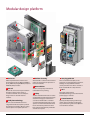
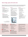
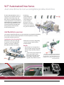
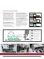
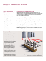
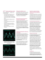
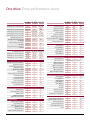
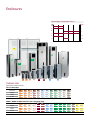
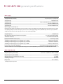
MAKING MODERN LIVING POSSIBLE VLT® AutomationDrive Series Reliable. Efficient. Engineered for design simplicity and high performance with a vast array of customized features, upgrades and options 100% Full load tested VLT® drives are factory tested insuring the highest level of quality and reliability. www.danfossdrives.com Modular design platform 1 10 10 2 3 11 7 4 12 6 13 8 9 5 1 Enclosure Meets requirements for enclosure class Protected Chassis (IP 20). Optional NEMA 1 (IP 21), NEMA 12 (IP 55), NEMA12 (IP 54) and NEMA 4X (IP 66) available. 2 DC coil Built-in DC coil ensures very low harmonic disturbance of the power supply, in accordance with IEC-1000-3-2. Compact design means no need for external modules. 3 Cold plate technology Built on a solid aluminum base that is integrated with the back panel to provide high mechanical stability, efficient cooling and the option of cold plate operation. www.danfossdrives.com 4 Conformal coating Available with a coated circuit board that makes the drive perfect for operation in harsh environments. 5 Removable fan The fan can be quickly removed and remounted for easy cleaning. 6 Safety The VLT® AutomationDrive FC 302 comes standard with the Safe Stop functionality suitable for Category 3 installations in accordance with EN 954-1 is standard on the VLT AutomationDrive FC 302 and optional on the VLT AutomationVT Drive FC 322. This feature prevents the drive from starting unintentionally. Profisafe is available as an option. 2 7 Hot-pluggable LCP The Local Control Panel (LCP) can be plugged in or unplugged during operation. Settings are easily transferred via the control panel from one drive to another or from a PC with MCT 10 setup software. 8 24 V 24 V supply keeps the VLT® AutomationDrive logic “alive” when the AC power supply is removed. 9 Control terminals Specially developed spring-loaded cage clamps enhance reliability and facilitate easy commissioning and service. Optional screw terminals available. 1.800.432.6367 Save energy, space, time and costs Danfoss’ unequalled experience was used to make the VLT® AutomationDrive Series the perfect match for industrial applications. You will find our dedicated sales and service staff all over the world, 24 hours a day. With a wide range of powerful standard and optional features, the VLT AutomationDrive Series provides the lowest overall cost of ownership of any drive available. Save energy Save time Save costs • High efficiency (>98%) • Sleep mode shuts off pumps when demand is low • Automatic energy optimization produces typical savings of 3–5% (up to 15% possible) • Flow compensation of setpoint • Unique cooling concept • Intuitive user interface with the new, award-winning local control panel (LCP) • One drive type for the full power range • Modular VLT design enables fast installation of options • Automatic motor adaptation streamlines installation by automatically tuning the drive to the motor without spinning it or requiring the load to be decoupled • Robust design and efficient monitoring significantly reduce maintenance requirements Protect your system with a series of pump-specific features: 10 Advanced option 12 Application option Free programmable MCO 305 Motion Controller with optional software for synchronizing, positioning and other advance applications using the VLT AutomationDrive FC 301 and FC 302. Optional cards expand system I/O capabilities by providing modules for: • I/O Expansion • Encoder or Resolver Inputs • Additional Relays • Safe PLC Interface • Expanded Cascade Control • Motor Thermistor Input languages (including Chinese) or have it customized with any language you like. Two of the languages can be changed by the user. Save space • Compact, modular design • Built-in DC-link reactors for harmonic suppression—no need for external AC input line reactors • Optional, integrated RFI filters throughout the power range • Integrated disconnects and fusing • • • • • • • • • • • Cascade controller Dry pump detection End of curve detection Motor alternation 2-step ramps (initial ramp) Pipe fill mode Real-time clock Password protection Overload trip protection Smart logic controller User-selectable variable or constant torque operation • NEMA/UL Type 12 (IP 54/55) and Nema 4X/IP66 enclosures can eliminate the need for separate panels Energy savings using a VLT AutomationDrive are achieved with even a modest reduction in speed. Advanced Cascade control for up to 8 pumps available for VLT AutomationVT Drive FC 322. 11 Fieldbus option Options for Fieldbus communication include Profibus, DeviceNet, CanOpen, Ethernet IP and Modbus TCP IP provide for tight system integration with a variety of industrial PLCs. 1.800.432.6367 13 Display options Input from our extensive user group significantly influenced the design and function of the new generation Local Control Panel (LCP). The removable LCP now comes with an improved user interface. Choose between six built-in 3 The info button accesses virtually all information contained in the printed operation manual. The Automatic Motor Adaptation (AMA), Quick Setup menu and large graphic display make commissioning and operation convenient and easy. The LCP also comes with a choice of numerical display, graphical display or blind cover. www.danfossdrives.com VLT® AutomationDrive Series Just one drive to run a complete production line The VLT® AutomationDrive series is a single drive concept that controls all operations from simple pump and fan to the most sophisticated motion control applications on any machine or production line. The standard versions cover a wide range of functions such as PLC functionality, automatic finetuning of motor control and selfanalysis of performance. Positioning, synchronizing, load estimation and even servo performance are also available. All versions share an identical user interface, so once you’ve operated one, you can use them all. Add flexibility to precision The new VLT® AutomationDrive lets you alter production speed without rebuilding the conveyor. The Precise Pulse Stop feature ensures that products are always where they should be on the line. Accelerate or slow the entire line Production speed can be changed at any time, even if the application involves several parts. The Precise Pulse Reference feature ensures that all conveyors are in sync by designating a master conveyor, which all other conveyors follow. Benefits: • The conveyor can be stopped at a precise location using an open loop system independent of production speed. • Precise Pulse Stop compensates for the speed of the object when it passes the stop sensor. This results in a precise stop, regardless of production speed. Press, place, and release—that’s all it takes for a reliable control cable connection that never needs servicing. www.danfossdrives.com The VLT® AutomationDrive supports all PROFIdrive profiles for automation. 4 The bottle is beneath the inspection camera at the exact moment the flash is activated. The VLT AutomationDrive ensures that production speed is adapted, even in complex operations along the entire production line. The fan is easily removed for cleaning of the heatsink. 1.800.432.6367 Built-in Smart Logic Controller The smart logic controller is a simple way to keep your drive, motor and application working together. The controller is programmed to monitor a specific process event. When the monitored event occurs a specific action can be programmed to execute. Up to 20 different events can be monitored before looping back to step one. The smart logic controller is able to monitor any parameter that can be defined in either a “true” or “false” state. This includes not only digital commands, but also logic expressions, allowing even sensor outputs to influence the operation. Temperature, pressure, flow, time, load, frequency, voltage and other parameters combined with the arithmetic comparators like “>”, “<”, “=”, logic operations like “or”, “and”, “not”, along with timer and counter functions allow the installer to form a series of logical statements that greatly integrates the drive into the manufacturing process. That’s why Danfoss calls it a “logic” controller; because you can program the controller to react to almost any event you choose. Analog 53 Value # CMP Alarm = Running AND IN # 19 OR IN # 32 00:00:00 Reset IN # 19 T Action # 1 Start button pressed Start button pressed Lower fast, drill motor on Slow speed limit SW reached Up limit SW Drill position Drill speed SW Bottom limit SW Time 1.800.432.6367 Bottom limit SW reached Raise drill, drill motor on Up limit SW reached Drill speed To disconnect wires, simply unplug the terminal blocks. Lower slow, drill motor on Plug-and-play is the way with the AutomationDrive. Even the power supply, sensor cables and looping connections are convenient plugs. 5 Stop drill, drill motor off The fieldbus option plugs in beneath the front panel. It can be turned upside down to allow for cable entry on top. www.danfossdrives.com Intelligent heat management Two cooling methods for different needs Total separation between cooling air and electronics allows for solutions where heat is removed outside cabinets. With VLT® AutomationDrive Series, a flanged heatsink kit is available for mounting the drive in the backplate of a cabinet. Forced convection cooling Cold plate cooling A fan blows cold air through the cooling ribs of the aluminum base. The channel is easily cleaned without touching electronics. External cooling is possible through the back side of the aluminum base. Flanged heatsink Wall mounted with forced cooling through the heatsink. A smart, dedicated kit allows D1 and D2 enclosures to be mounted in Rittal cabinets so cool air removes 85% of excess heat without contact to the electronics. VLT® MCO 305 Motion Controller The MCO 305 is an integrated Motion Controller that can be provided with embedded firmware for simple synchronizing, positioning, and center winding applications. Integrating this option into the VLT AutomationDrive FC 301 or FC 302 transforms the drive into a highly intelligent system providing accurate dynamic motion control for the most sophisticated applications. The MCO 305 option utilizing the MCT 10 programming tools provides complete programming capabilities allowing the user to completely customize the VLT AutomationDrive for the most demanding applications. DC coils reduce harmonic noise and protect the drive. Safety installations can be connected directly to the VLT® AutomationDrive. Cold plate. www.danfossdrives.com 6 1.800.432.6367 Award-winning, user-friendly interface • Changes Made Menu displays the parameters to which changes have been made • Function Setup Menu provides quick setup for specific applications • Logging Menu provides access to operation history 1 4 3 Illumination • Illuminated LEDs indicate which function is active 2 5 3 6 4 Menu structure • Based on the field-proven matrix system used in previous VLT® Series drives • Menu shortcuts access specific functions • Edit and operate in different setups simultaneously The VLT® AutomationDrive has an award-winning Local Control Panel (LCP) that was designed based on user feedback. With a well-structured menu system, the VLT® AutomationDrive ensures fast commissioning and easy access to its many powerful functions. 5 Other benefits 1 Graphical display • Informative overview • Six lines of display • Graphical or numerical display of information • Readout in user-selectable engineering units • Select from up to 27 languages as standard • Backlit for increased visibility 2 Quick Menus • Danfoss-defined Quick Menu • My Personal Menu allows users to define their own menus of commonly accessed parameters 1.800.432.6367 • The keypad is removable during operation • Upload/download setups between drives using the keypad • Remote mounting kit available for panel installation • Hand / off / auto buttons for easy switching between manual and automatic control 6 Additional buttons • Info: an “onboard manual” that provides specific information about each parameter • Cancel: exits current parameter without saving changes • Alarm log: easy access to a list of all previous alarm conditions 7 www.danfossdrives.com Built for a variety of applications with a wide range of advanced features Quicker handling of small loads Reliable, accurate load handling Gentle on goods—and brakes Equipment is typically sized to handle a maximum load, and speed is usually determined by this maximum load. Changing conditions influence the operation of cranes and other equipment. Depending on position and load, a crane tends to shake when stopping or starting, because it’s calibrated to an average load. When stopped, the AutomationDrive will slow a hoist to zero before activating the mechanical brake. This results in gentler handling, and virtually eliminates wear on the brake. The ability to change speed automatically allows equipment to operate at a partial or minimum load. The drive estimates the load and maximizes production speed. The VLT® AutomationDrive estimates motor currents generated by actual loads and compensates to make the crane start and stop smoothly just where it should. The same benefits apply to hoists and elevators. NEMA 4X (IP 66) for harsh environments All VLT® AutomationDrives have manganic phosphor rear bodies. The backs of NEMA 4X (IP 66) enclosures are dip-coated with epoxy or polyester spray finish (60–100 µm). The cover is powder coated (80–100 µm). The silicone gasket is tested with various detergents. Benefits: • Low torque ripple gives smooth operation • Precise load estimation allows for precise positioning regardless of load • Load estimation saves time and speeds up production safely and intelligently • Full holding torque capability at 0 RPM gives a smooth ride and reduces mechanical wear on gears and brakes, minimizing maintenance and maximizing production up-time Small footprint Throughout the entire power range, all sizes of VLT® AutomationDrives are even smaller than comparable previous drives. No dimension has increased, and volumes are typically 20% smaller. The VLT® AutomationDrive provides crane and hoist applications with smooth, precise operation while reducing wear and tear on driven equipment. Coated control boards are avilable for harsh environments. www.danfossdrives.com 8 1.800.432.6367 One-wire safety The VLT® AutomationDrive FC 302 and the VLT® AutomationVT Drive (optionally) are equipped with with safe stop functionality suitable for category 3 installations as defined by EN 954-1. This standard feature prevents a drive from starting accidentally. The safe stop terminal can be used to “safe coast” the motor - the stop function satisfies stop category 3 EN 60204-1. Expensive and bulky external components can be omitted, wiring simplified, and downtime minimized with this solution. The safety signals can be transferred via discrete signals wiring (in compact machinery) or safe bus communication (in extended manufacturing plants). Omissible Since it’s approved for safety category 3 applications, the VLT® AutomationDrive and AutomationVT Drive is a perfect match for the Pilz safety relay. The electrical connection is extremely simple—just one wire. The VLT® AutomationDrive and AutomationVT Drive is approved for providing safe stop in category 3 installations without the need for feedback signals from the drive to the safety relay. Before After 600 & 690 V When torque is the issue In all winders, the torque required to accelerate and decelerate an application varies with the load. With center winders the required torque even varies with the dimension of the roll. Torque mode with high-precision torque control is needed. Both the VLT AutomationDrive and VLT AutomationVT Drive can be ordered for either 575 volt or 690 volt applications found in the petrochemical, gas supply, mining and forestry markets. The 690 volt version is available to 1.4 MW of power. It is essential in winding operations to fully control the tension of the material being wound. To maintain tangential tension independently of the line speed and roll diameter, the drive is able to dynamically follow a wide range of torque references. 1.800.432.6367 9 www.danfossdrives.com Designed with the user in mind The VLT® AutomationDrive maximizes system reliability with built-in protection: • • • • • • • • • • • • • • • System overloads Motor failures Motor and drive overheating Voltage disturbances Power surges Loss of phase Phase-to-phase and phase-toground short circuit Ground fault Switching on input/output Electrical disturbances Overvoltage Overcurrent Undervoltage External fault Overtemperature Minimize motor noise and heating with ASFM With the ASFM (Adjustable Switching Frequency Modulation) function, the switching frequency is adjusted automatically in relation to the speed of the motor. As speed is reduced, the switching frequency increases to ensure optimally low motor noise and reduce motor heating. Output protection for longer motor life VLT® AutomationDrives incorporate both DC-link reactors and motor output protection as standard design features. This provides short circuit protection and allows unlimited switching on the output without damage to the drive, eliminating the need for additional output reactors or switch interlocks. The DC-link reactors improve overall efficiency by increasing the power factor and lowering the ripple current in the bus voltage providing an almost threefold increase in capacitor and drive life. As a result, motor operation is smooth and quiet and longer motor life can be expected. Hall effect current transducers measure current flowing on all three motor phases. This provides highly responsive and accurate feedback to the VLT control circuit for optimum motor protection and performance. Cascade Controllers Provide additional relays for staging of additional pumps: • MCO 101 extended cascade controller controls up to five pumps • MCO 102 advanced cascade controller controls up to eight pumps Cascade controller option cards extend the capabilities of the VLT® AutomationVT Drive FC 322, allowing the control of up to eight parallel pumps configured to appear to the sytem as a single larger pump. Individual pumps are automatically turned on (staged) and turned off (destaged) as needed to satisfy the required system output for flow or pressure. The speed of the pumps is also controlled to provide a continuous range of system output. Available as a factory-installed option or a field-installed accessory, cascade controller option cards provide constant pressure or level control while reducing water hammer and energy consumption. They also eliminate the need for PLCs and external controllers. www.danfossdrives.com A typical AutomationVT Drive FC 322 installation utilizing the Cascade Controller option in conjunction with three additional AutomationVT Drives FC 322 to operate one to four pumps as demand requires. 10 1.800.432.6367 VVCPLUS output switching pattern Reduced installation cost Unique digital VVC control provides: Dual DC-link reactors reduce the input RMS current to less than or equal to the output current. This greatly reduces the cable size requirement and the subsequent cost of installation. PLUS voltage vector • A nearly perfect output sine wave that reduces the overshooting and undershooting of voltage and current generated by standard PWM drives • Fully rated motor voltage at rated frequency • Increased efficiency for both drive and motor • Full motor performance without derating; no additional heating of motor windings • Motor cable lengths up to 1000’ standard Minimal harmonic distortion/ maximum power factor DC-link reactors reduce the harmonic distortion currents that a variable frequency drive injects back into the AC line. The properly sized reactors in a VLT AutomationDrive can reduce line harmonic currents by up to 40% of the fundamental current. This eliminates the need and cost of additional AC line reactors and their resultant line voltage reduction. Thermal protection for the drive and motor The ETR (Electronic Thermal Relay) is an open loop method built into the VLT AutomationDrive software to guard against motor overheating, requiring no additional sensors or wiring. This function is UL recognized (Class 20) as an effective guard against motor thermal overload. Brand “X” PWM scope trace (top) compared to smoother VVCPLUS scope trace (bottom). The VLT AutomationDrive has built-in thermal protection and also accepts thermistor signal input from the motor to create closed loop thermal protection for the entire system. Input line protection from extreme running conditions Short circuit The VLT AutomationDrive incorporates 3 hall effect sensors, one in each of the three motor phases to protect against short circuits. A short circuit between two output phases (or to ground) will shut down the drive as soon as the current exceeds the maximum value. Line disturbances and transients To protect itself from AC line voltage disturbances, the drive monitors all three phases and interrupts drive operation in the event of phase loss or imbalance. Transients on the AC line are suppressed by MOVs as well as zener diodes for extreme transients. Danfoss VLT AutomationDrives meet VDE 0160 (European standard—2.3 x line voltage for 1.3 msec) for transient protection. Voltage sags and surges The VLT AutomationDrive is designed for a wide range of operating conditions. The 480 volt drive will operate from 342–528 VAC. The 230 volt drives will operate on 180–264 VAC. 575 volt drives will operate on 495–660 VAC and 690 volt drives will operate on 472–759 VAC. Full rated motor voltage and torque can be delivered with voltage dips down to 10% under nominal AC line voltage. During an AC line drop-out, the VLT AutomationDrive continues until the intermediate circuit voltage drops below the minimum stop level, which is typically 15% below the VLT AutomationDrive’s lowest rated supply voltage. Ground fault The VLT AutomationDrive provides complete protection from potentially damaging ground fault conditions on both the supply side and the motor side. 1.800.432.6367 11 www.danfossdrives.com One drive. Three performance levels. FC 301 FC 302 FC 322 FC 301 FC 302 FC 322 Interface Operating Power Range 200-240 Vac [HP] Power Range 380-480 Vac [HP] Power Range 380-500 Vac [HP] Power Range 525-600 Vac [HP] Power Range 525-690 Vac [KW] Ambient Temperature C (average for 24 hours without de-rating) Ambient Temperature with de-rating Variable Switching Frequency 1-16 Khz 1/3 to 50 1/3 to 50 50 50 50 55 55 55 √ √ √ Numeric Keypad Graphical Keypad Info/Help Function Personal Menu Regional Settings Multi-Lingual Support Change made Restore Previous Setting Password Protection 1/3 to 60 1/2 to 1/2 to 100 na 1350 na 1/2 to 1200 na na 1 to 100 1 to 125 na 11 to 1000 11 to 1200 50/75 m <5 m <50 m <10 m Analog Inputs Analog Outputs Digital Inputs Digital Ouptuts Relay Outputs 150/300 m 150/300 m <5 m <5 m <150 m <150 m <50 m <50 m √ na na √ √ √ √ na na √ √ √ na √ √ √ √ √ √ √ √ √ √ √ √ √ √ √ √ √ √ √ √ √ na √ RS-485 (built in) protocol (built in) USB Port (built in) Optional Profibus Optional DeviceNet Optional CanOpen Optional Ethernet Optional Modbus TCP/IP √ √ √ √ √ √ √ √ √ √ √ √ √ √ √ √ √ √ √ √ √ na std opt na √ na √ √ √ Analog Inputs Analog Outputs Digital Inputs Digital Ouptuts Relay Outputs Encoder Resolver Safe PLC Interface Thermistor Input Extended Cascade Control www.danfossdrives.com √ √ √ √ √ 2 1 5 1 1 2 1 6 2 2 2 1 6 2 2 √ √ √ Modbus RTU or FC Protocol √ √ √ √ √ √ √ √ √ √ √ na √ √ √ √ √ √ 2 1 3 2 3 1 1 na na na 2 1 3 2 3 1 1 1 √ na 3 3 3 2 3 na na na √ √ na √ √ √ √ na na √ √ √ √ √ √ na na na na na Other Functions Advanced Cascade Control Programmable Motion Control Positioning Control Synchronizing Control Center Winding Control SALT Special Functions Smart Logic Controller Logic Rule Control Safe Stop Functionality (EN 954-1 cat 3) Real Time Clock Automatic Motor Adaptation √ I/O Expansion Enclosure Styles Chassis (IP00) Protected Chassis (IP20) NEMA 1 (IP21) NEMA 12 (IP55/54) NEMA 4X Indoor (IP66) opt std √ √ √ √ Communications Control Modes Voltage Vector Control (VVC+) Flux Vector Control Permanent Magnet Motor Automatic Energy Optimization (AEO) Flying Start Over Voltage Control (OVC) Controlled Ramps Linear & S Ramps Process PID Control Precise Start/Stop Digital Potentiometer Preset References opt std √ √ √ √ Std Input/Output Cable Length Shielded/Unshielded RFI EN55011 class A2 industry RFI EN55011 class A1 industry RFI EN55011 class B domestic opt std √ √ √ √ 12 1.800.432.6367 Enclosures Broad Range of Protection Classes IP 66 1/3 to 125 NEMA 4x 55 1/3 to 125 12 125 to 1500 54 1/3 to 1500 21 20 12 1 1/3 to 125 Panel 125 to 600 00 10 100 500 Panel 1000 1500 F1 E1 D2 E2 D4 D1 D3 A2 A3 A4 A5 B1 B2 C1 C2 Cabinet sizes Dimensions shown in inches. Chassis (IP20, IP00) Frame Size A1 A2 A3 B3 B4 C3 C4 D3 D3H D4 D4H E2 Height 7.9 10.6 10.6 16.5 23.7 25.0 31.7 39.3 33.3 50.3 41.3 59.0 Width 3.0 3.5 5.1 6.5 9.1 12.1 14.6 16.1 9.8 16.1 13.8 23.0 Depth 8.1 8.1 8.1 9.8 9.5 13.1 13.1 14.7 14.8 14.7 14.8 19.4 D1H D2 D2H E1 F1 F3 NEMA 1, NEMA 12, NEMA 4X Indoor (IP21, IP55, IP54, IP66) Frame Size A2 A3 A4 A5 B1 B2 C1 C2 D1 Height 14.6 14.6 15.4 16.5 18.9 25.6 26.8 30.3 45.6 33.7 60.6 41.7 78.7 89.8 89.8 Width 3.5 5.1 7.9 9.5 9.5 9.5 12.1 14.6 16.5 12.795 16.5 16.5 23.6 55.1 78.6 Depth 8.1 8.1 7.0 7.9 10.3 10.3 12.2 13.2 14.7 14.9 14.7 14.9 19.4 23.9 23.9 1.800.432.6367 13 www.danfossdrives.com Current and power by enclosure size 3 Phase 380-480 Vac (FC 322 & FC 301) 380-500 Vac (FC 302 only) 3 Phase 200-230 Vac NO 110% (FC 322) Output Current Amps PK25 PK37 PK55 PK75 P1K1 P1K5 P2K2 P3K0 P3K7 P4K0 P5K5 P7K5 P11K P15K P18K P22K P30K P37K P45K P55K P75K P90K P110 P132 P160 P200 P250 P315 P355 P400 P450 P500 P560 P630 P710 P800 P900 P1M0 P1M2 P1M4 HO 160% (FC 301 & FC 302) KW HP Output Current Amps 1.8 2.4 3.5 4.6 6.6 7.5 10.6 12.5 16.7 0.25 0.37 0.55 0.75 1.1 1.5 2.2 3.0 3.7 1/3 1/2 3/4 1 1-1/2 2 3 4 5 1.8 2.4 3.5 4.6 6.6 7.5 10.6 12.5 16.7 0.25 0.37 0.55 0.75 1.1 1.5 2.2 3.0 3.7 1/3 1/2 3/4 1 1-1/2 2 3 4 5 24.2 30.8 46.2 59.4 74.8 88.0 115.0 143.0 170.0 5.5 7.5 11.0 15.0 18.5 22.0 30.0 37.0 45.0 7-1/2 10 15 20 25 30 40 50 60 24.2 30.8 46.2 59.4 74.8 88.0 115.0 143.0 5.5 7.5 11.0 15.0 18.5 22.0 30.0 37.0 7-1/2 10 15 20 25 30 40 50 www.danfossdrives.com Shaft Output Shaft Output KW HP 14 NO 110% (FC 322) Output Current Amps (480 V) HO 160% (FC 301 & FC 302) KW HP Output Current Amps (480 V) 1.2 1.6 2.1 2.7 3.4 4.8 6.3 0.37 0.55 0.75 1.1 1.5 2.2 3.0 1/2 3/4 1 1-1/2 2 3 4 8.2 11.0 14.5 21.0 27.0 34.0 41.0 52.0 65.0 80.0 105.0 130.0 160.0 190.0 240.0 303.0 361.0 443.0 540.0 590.0 678.0 730.0 780.0 890.0 1050.0 1160.0 1380.0 4.0 5.5 7.5 11.0 15.0 18.5 22.0 30.0 37.0 45.0 55.0 75.0 90.0 110.0 132.0 160.0 200.0 250.0 315.0 355.0 400.0 450.0 500.0 560.0 630.0 710.0 800.0 5 7-1/2 10 15 20 25 30 40 50 60 75 100 125 150 200 250 300 350 450 500 550 600 650 750 900 1000 1200 1530.0 1000.0 1350 Shaft Output Shaft Output KW HP 1.2 1.6 2.1 2.7 3.4 4.8 6.3 0.37 0.55 0.75 1.1 1.5 2.2 3.0 1/2 3/4 1 1-1/2 2 3 4 8.2 11.0 14.5 21.0 27.0 34.0 41.0 52.0 65.0 80.0 105.0 130.0 160.0 190.0 240.0 303.0 361.0 443.0 540.0 590.0 678.0 730.0 780.0 890.0 1050.0 1160.0 1380.0 4.0 5.5 7.5 11.0 15.0 18.5 22.0 30.0 37.0 45.0 55.0 75.0 90.0 110.0 132.0 160.0 200.0 250.0 315.0 355.0 400.0 450.0 500.0 560.0 630.0 710.0 800.0 5 7-1/2 10 15 20 25 30 40 50 60 75 100 125 150 200 250 300 350 450 500 550 600 650 750 900 1000 1200 1.800.432.6367 Frame sizes A B PK25 PK37 PK55 PK75 P1K1 P1K5 P2K2 P3K0 P3K7 P4K0 P5K5 P7K5 P11K P15K P18K P22K P30K P37K P45K P55K P75K P90K P110 P132 P160 P200 P250 P315 P355 P400 P450 P500 P560 P630 P710 P800 P900 P1M0 P1M2 P1M4 Output Current Amps (575 V) KW 1.7 2.4 2.7 3.9 4.9 6.1 9.0 11.0 18.0 22.0 27.0 34.0 41.0 52.0 62.0 83.0 100.0 131.0 1.800.432.6367 HO 160% (FC 302) NO 110% (FC 322) HP Output Current Amps (575V) KW HP 0.75 1.1 1.5 2.2 3.0 1 1-1/2 2 3 4 1.7 2.4 2.7 3.9 4.9 0.75 1.1 1.5 2.2 3.0 1 1-1/2 2 3 4 4.0 5.5 7.5 11.0 15.0 18.5 22.0 30.0 37.0 45.0 55.0 75.0 90.0 5 7-1/2 10 15 20 25 30 40 50 60 75 100 125 6.1 9.0 11.0 18.0 22.0 27.0 34.0 41.0 52.0 62.0 83.0 100.0 4.0 5.5 7.5 11.0 15.0 18.5 22.0 30.0 37.0 45.0 55.0 75.0 5 7-1/2 10 15 20 25 30 40 50 60 75 100 Shaft Output D E 3 Phase 525-690 Vac (FC 322 & FC 302) 3 Phase 525-600 Vac (FC 322 & FC 302) NO 110% (FC 322) C Shaft Output 15 Output Current Amps (690 V) Shaft Output 18.0 22.0 27.0 34.0 41.0 46.0 54.0 73.0 86.0 108.0 131.0 155.0 192.0 242.0 290.0 344.0 11.0 15.0 18.5 22.0 30.0 37.0 45.0 55.0 75.0 90.0 110.0 132.0 160.0 200.0 250.0 315.0 410.0 450.0 500.0 570.0 630.0 730.0 850.0 945.0 1060.0 1260.0 1415.0 400.0 450.0 500.0 560.0 630.0 710.0 800.0 900.0 1000.0 1200.0 1400.0 KW HO 160% (FC 302) Output Current Amps (690 V) Shaft Output 18.0 22.0 27.0 34.0 41.0 46.0 54.0 73.0 86.0 108.0 131.0 155.0 192.0 242.0 290.0 344.0 380.0 410.0 11.0 15.0 18.5 22.0 30.0 37.0 45.0 55.0 75.0 90.0 110.0 132.0 160.0 200.0 250.0 315.0 355.0 400.0 500.0 570.0 630.0 730.0 850.0 945.0 1060.0 1260.0 500.0 560.0 630.0 710.0 800.0 900.0 1000.0 1200.0 KW www.danfossdrives.com Options & accessories Slot A All options are built in and tested at the factory VLT® PROFIBUS DP V1 MCA 101 Operating the frequency converter via a fieldbus lets you reduce the cost of your system, communicate faster and more efficiently, and benefit from an easier user interface •PROFIBUS DP V1 gives you wide compatibility, a high level of availability, support for all m ajor PLC vendors, and compatibility with future versions Ordering number •Fast, efficient communication, transparent installation, advanced diagnosis and parameter access with auto configuration of process data via GSD-file •A-cyclic parameterization using PROFIBUS DP V1, PROFIdrive or Danfoss FC profile state machines, PROFIBUS DP V1, Master Class 1 and 2 VLT® AutomationDrive VLT® AutomationVT Drive 130B1100 uncoated 130B1200 coated FC 322 FC 301 FC 302 VLT® DeviceNet MCA 104 DeviceNet offers robust, efficient data handling thanks to advanced producer/consumer technology. •This modern communications model offers key capabilities that let you effectively determine what information is needed and when Ordering number •You will also benefit from ODVA’s strong conformance t esting policies, which ensure that products are interoperable VLT® AutomationVT Drive 130B1102 uncoated 130B1202 coated VLT® AutomationDrive FC 322 FC 301 FC 302 VLT® CAN Open MCA 105 High flexibility and low cost are two of the “cornerstones” for CAN Open. The CAN Open option for the AutomationDrive is fully equipped with both high priority access to control and status of the Drive (PDO Communication) and access to all parameters through acyclic data (SDO Communication). Ordering number For interoperability the option has implemented the DSP402 AC drive profile. This all guarantees standardized handling, interoperability, low cost, and seamless integration with the MCO 305 Motion Controllers bus structure for master/slave applications. VLT® AutomationVT Drive FC 322 130B1103 uncoated 130B1205 coated VLT® AutomationDrive FC 301 FC 302 VLT® EtherNet IP MCA 121 EtherNet will become the future standard for communication at the factory floor. The EtherNet Option is based on the newest technology available for industrial use and handles even the most demanding requirements. EtherNet/IP extends commercial off-the-shelf EtherNet to the Common Industrial Protocol (CIP™)—the same upper-layer protocol and object model found in DeviceNet. Ordering number VLT® AutomationVT Drive 130B1119 uncoated 130B1219 coated www.danfossdrives.com The VLT® MCA 121 offers advanced features as: •Built-in high performance switch enabling linetopology, and eliminating the need for external switches •Advanced switch and diagnoses functions •Built-in web server •E-mail client for service notification 16 VLT® AutomationDrive FC 322 FC 301 FC 302 1.800.432.6367 Slot A VLT® Modbus TCP MCA 122 VLT® Modbus TCP was introduced in 1998 and is today one of the most developed, proven, and complete industrial Ethernet network solutions available for manufacturing automation. Application protocols: •Modbus TCP for controlling and parameter setting •HTTP (Hypertext Transfer Protocol) for diagnosis via built-in web server Ordering number 130B1196 uncoated 130B1296 coated •SMTP (Simple Mail Transfer Protocol) for e-mail notification •DHCP (Dynamic Host Configuration Protocol) automatic IP address configuration •FTP (File Transfer Protocol) file up– and download •TCP/IP (legacy TCP/IP) transparent Socket Channel connection to MCT 10 VLT® AutomationVT Drive VLT® AutomationDrive FC 322 FC 301 FC 302 Slot B VLT® General Purpose I/O MCB 101 I/O option offers an extended number of control inputs and outputs. •3 digital inputs 0-24 V: Logic ‘0’ < 5 V; Logic ‘1’ > 10V •2 analog inputs 0-10 V: Resolution 10 bit plus sign Ordering number 130B1125 uncoated 130B1212 coated •2 digital outputs NPN/PNP push pull •1 analog output 0/4-20 mA •Spring loaded connection •Separate parameter settings VLT® AutomationVT Drive VLT® AutomationDrive FC 322 FC 301 FC 302 VLT® Encoder Input MCB 102 Ordering number 130B1115 uncoated 130B1203 coated 1.800.432.6367 •Power supply for encoders •RS422 interface •Plug-and-play principle •Fit to all FC 300 AutomationDrives •Connection to all standard 5 V incremental encoders •Spring-loaded connection VLT® AutomationVT Drive FC 322 Options & Accessories A universal option for connection of encoder feedback from either a motor or a process. Feedback for asynchronous or brushless servo (Permanent Magnet) motors. •Encoder module supports: – Incremental encoders – SinCos encoders as Hyperface® VLT® AutomationDrive FC 301 FC 302 17 www.danfossdrives.com Options & accessories Slot B All options are built in and tested at the factory VLT® Resolver Input MCB 103 Supports resolver feedback from brushless servo motors, and feedback for flux vector controlled asynchronous motors in rough environment. •Primary Voltage.............................................. 2 -8 Vrms •Primary Frequency.......................... 2.0 kHz – 15 kHz Ordering number •Primary current max................................. 50 mA rms •Secondary input voltage................................. 4 Vrms •Spring loaded connection •Separate parameter settings VLT® AutomationVT Drive VLT® AutomationDrive FC 322 130B1127 uncoated 130B1227 coated FC 301 FC 302 VLT® Relay Option MCB 105 Lets you extend relay functions with 3 a dditional relay outputs. Max. terminal load: • AC-1 Resistive load ............................ 240 V AC 2 A • AC-15 Inductive load @cos fi 0.4 ................................240 V AC 0.2 A • DC-1 Resistive load .............................. 24 V DC 1 A • DC-13 Inductive load @cos fi 0.4 ..................................24 V DC 0.1 A Ordering number Min. terminal load: • DC 5 V.................................................................. 10 mA • Max switch rate at rated load/min. load ................................ 6 min-1/20 sec-1 • Plug-and-play principle, fits into slot B • Protects control cable connection • Spring-loaded control wire connection • Selection of relay functions in normal parameter settings VLT® AutomationVT Drive 130B1110 uncoated 130B1210 coated VLT® AutomationDrive FC 322 FC 301 FC 302 VLT® Safe PLC I/O MCB 108 The FC 302 provides a safety input based on a single pole 24 V DC input. •For the majority of applications this input enables the user to implement safety in a cost-effective way. For application that works with more advanced products like Safety PLC, Ordering number Lightcurtains etc., the new Safe PLC interface enables the connection of a two wire safety link •The Safe PLC Interface allows the Safe PLC to interrupt on the plus or the minus link without interfering the sense signal of the Safe PLC VLT® AutomationVT Drive VLT® AutomationDrive FC 322 FC 301 130B1120 uncoated 130B1220 coated FC 302 VLT® Analog I/O Option MCB 109 This Analog input/output option is easily fitted in the frequency converter for upgrading to advanced performance and control using the additional in/outputs.This option also upgrades the frequency converter with a battery back-up supply for the clock built into the frequency converter. This provides stable use of all frequency converter clock functions as timed actions etc. Ordering number The back-up battery typically lasts for 10 years, depending on environment. VLT® AutomationVT Drive FC 322 130B1143 uncoated 130B1243 coated www.danfossdrives.com •3 analog inputs, each configurable as both voltage and temperature input •Connection of 0-10 V analog signals as well as PT1000 and NI1000 temperature inputs •3 analog outputs each configurable as 0-10 V outputs •Incl. Back-up supply for the standard clock function in the frequency converter VLT® AutomationDrive FC 301 FC 302 18 1.800.432.6367 Slot B VLT® PTC Thermistor Card MCB 112 With the MCB 112 PTC Thermistor Card, the Danfoss VLT® AutomationDrive FC 302 now o ffers improved surveillance of the motor condition compared to the built-in ETR function and thermistor terminal. Ordering number •Protects the motor from overheating •ATEX approved for use in potentially e xplosive atmospheres •Uses Safe Stop function, which is approved in accordance with Cat. 3 EN954-1 VLT® AutomationVT Drive VLT® AutomationDrive FC 322 FC 301 FC 302 NA uncoated 130B1137 coated VLT® Sensor Input Card MCB 114 The option protects the motor from being overheated by monitoring the bearings and windings temperature in the motor. The limits as well as the action are adjustable and the individual sensor temperature is visible as a read out in the display or by field bus. Ordering number •Protects the motor from overheating •Three self-detecting sensor inputs for 2 or 3 wire PT100/PT1000 sensors •One additional analog input 4-20mA VLT® AutomationVT Drive FC 322 130B1172 uncoated 130B1272 coated VLT® AutomationDrive FC 301 FC 302 VLT® Extended Cascade Controller MCO 101 Easily fitted and upgrades the built-in cascade controller to operate more pumps and more advanced pump control in master/follower mode. Ordering number •Up to 6 pumps in standard cascade setup •Up to 5 pumps in master/follower setup •Technical specification: See MCB 105 Relay Option VLT® AutomationVT Drive FC 322 130B1118 uncoated 130B1218 coated VLT® AutomationDrive FC 301 FC 302 Options & Accessories USB extension USB extension for IP 55 and IP 66 enclosures. Makes the USB connector available outside the drive. The USB extension is designed for mounting in a cable gland in the bottom of the drive, which makes PC communication very easy even in drives with high IP rating. Ordering number USB extension for A5-B1 enclosures, 350 mm cable............................................... 130B1155 USB extension for B2-C enclosures, 650 mm cable............................................... 130B1156 VLT® AutomationVT Drive VLT® AutomationDrive FC 322 FC 301 130B1155 350 mm cable 130B1156 650 mm cable 1.800.432.6367 FC 302 19 www.danfossdrives.com Options & accessories Slot C VLT® Advanced Cascade Controller MCO 102 Easily fitted and upgrades the built-in cascade controller to operate up to 8 pumps and more advanced pump control in master/follower mode. Ordering number The same cascade controller hardware goes for for the entire power range up to 1.2 MW. •Up to 8 pumps in standard cascade setup •Up to 8 pumps in master/follower setup VLT® AutomationVT Drive FC 322 130B1154 uncoated 130B1254 coated VLT® AutomationDrive FC 301 FC 302 VLT® Extended Relay Card MCB 113 The Extended Relay Card MCB 113 adds inputs/ outputs to VLT® AutomationDrive for increased flexibility. Ordering number VLT® AutomationVT Drive FC 322 130B1164 uncoated 130B1264 coated VLT® Motion Control MCO 305 An integrated programmable Motion Controller for VLT® AutomationDrive FC 301 and FC 302; it adds fuctionality and flexibility to the already very comprehensive standard functionality of these drives. MCO 305 is optimized for all types of positioning and synchronizing applications. •Basic features: Synchronization (electronic shaft), Positioning and electronic Cam control Ordering number •7 digital inputs •2 analog outputs •4 SPDT relays •Meets NAMUR recommendations •Galvanic isolation capability VLT® AutomationDrive FC 301 FC 302 •2 inputs supporting both incremental and absolute encoders •1 encoder output (virtual master function) •10 digital inputs •8 digital outputs •Sending and receiving data via fieldbus interface (requires fieldbus option) • PC software tools for programming and commissioning VLT® AutomationVT Drive FC 322 130B1134 uncoated 130B1234 coated VLT® AutomationDrive FC 301 FC 302 VLT® Synchronizing Control MCO 350 The Synchronizing Controller option for VLT® AutomationDrive expands the functional properties of the converter in synchronizing applications. It replaces traditional mechanical solutions. •Display of actual synchronizing error on frequency converter control panel •Speed synchronizing Ordering number VLT® AutomationVT Drive FC 322 130B1152 uncoated 130B1252 coated www.danfossdrives.com •Position (angle) synchronizing with or without marker correction •On-line adjustable gear ratio •On-line adjustable position (angle) offset •Encoder output with virtual master function for synchronization of multiple followers • Homing 20 VLT® AutomationDrive FC 301 FC 302 1.800.432.6367 Slot C VLT® Positioning Control MCO 351 The Positioning Controller option offers a host of user-friendly benefits for positioning applications in many industries. They are based on a range of thought-through and innovative features. •Direct positioning via Fieldbus •Relative positioning •Absolute positioning •Touch probe positioning Ordering number •End limit handling (software and hardware) •Mechanical brake handling (programmable hold delay) •Error handling •Jog speed/manual operation •Marker related positioning •Home function VLT® AutomationVT Drive FC 322 130B1153 uncoated 130B1253 coated VLT® AutomationDrive FC 301 FC 302 VLT® Center Winder MCO 352 With the closed loop center winder control material is evenly wound up regardless of the production speed. Ordering number •Follows line speed •Diameter calculator adjusts winder reference •Tension PID adjusts reference VLT® AutomationVT Drive FC 322 130B1165 uncoated 130B1266 coated VLT® AutomationDrive FC 301 FC 302 Slot D VLT® 24 V DC Supply Option MCB 107 The option is used to connect an external DC supply to keep the control section and any installed option active by mains power down. • Input voltage range......24 V DC +/- 15% (max. 37 V in 10 sec.) • Max. input current ............................................ 2.2 A Ordering number 1.800.432.6367 VLT® AutomationVT Drive VLT® AutomationDrive FC 322 FC 301 FC 302 21 Options & Accessories 130B1108 uncoated 130B1108 coated • Max. cable length ............................................. 75 m • Input capitance load ....................................< 10 uF • Power-up delay ................................................< 0.6 s • Easy to install in drives in existing machines • Keep the control board and options active by power cut • Keep fieldbuses active by power cuts www.danfossdrives.com Options & accessories LCP LCP 102 Graphical Local Control Panel •Multi-language display •Status messages •Quick menu for easy c ommissioning •Parameter setting and explanation of parameter function •Adjusting of parameters •Full parameter backup and copy function Ordering number •Alarm logging •Info button – explains the function of the selected item on display •Hand-operated start/stop, or Automatic mode selection •Reset function •Trend graph VLT® AutomationVT Drive 130B1107 VLT® AutomationDrive FC 322 FC 301 FC 302 LCP 101 Numerical Local Control Panel The numerical control panel offers an excellent MMI interface to the drive. •Status messages •Quick menu for easy commissioning Ordering number •Parameter setting and adjusting •Hand-operated start/stop function or Automatic mode select •Reset function VLT® AutomationVT Drive 130B1124 VLT® AutomationDrive FC 322 FC 301 FC 302 LCP Panel Mounting Kit Ordering number www.danfossdrives.com VLT® AutomationVT Drive VLT® AutomationDrive FC 322 FC 301 FC 302 130B1113 – Incl. graphical LCP, fasteners, 3 m cable and gasket 130B1114 – Incl. numerical LCP, fasteners and gasket 130B1117 – Mounting kit for all LCP’s including fasteners, 3 m cable and gasket 130B1129 – LCP front mounting IP55/IP66 130B1170 – Panel Mouting Kit for all LCP w.o. cable 22 1.800.432.6367 Accessories Profibus Adapter Sub-D9 Connector For use with option A The adapter makes linking of fieldbus connections pluggable. Ordering number VLT® AutomationVT Drive 130B1112 VLT® AutomationDrive FC 322 FC 301 FC 302 Decoupling Plate for Fieldbus Cables For use with option A Strengthens fieldbus mounting. Ordering number VLT® AutomationVT Drive VLT® AutomationDrive FC 322 FC 301 FC 302 130B0524 To be used only for IP 20/NEMA type 1 units up to 7.5 kW IP 21/Type 1 (NEMA1) Kit The IP 21/Type 1 (NEMA1) kit is used for installation of VLT® drives in dry environments. The enclosure kits are available for frame sizes A1, A2, A3, B3, B4, C3 and C4 Ordering number •Supports VLT® drives from 1.1 to 90 kW •Used on standard VLT® drive with or without mounted option modules •IP 41 on top side •PG 16 and PG 21 holes for glands VLT® AutomationVT Drive VLT® AutomationDrive FC 301 FC 302 130B1121 For frame size A1 130B1122 For frame size A2 130B1123 For frame size A3 130B1187 For frame size B3 130B1189 For frame size B4 130B1191 For frame size C3 130B1193 For frame size C4 1.800.432.6367 23 Options & Accessories FC 322 www.danfossdrives.com Options & accessories Power Options VLT® Brake Resistors Energy generated during braking is absorbed by the resistors, protecting electrical components from heating up. Danfoss brake resistors cover the full power range. Ordering number •Quick braking of heavy load • .Braking energy is only absorbed into the brake resistor • .External mounting makes it possible to use the generated heat • All necessary approvals are available VLT® AutomationVT Drive See relevant Design Guide VLT® AutomationDrive FC 322 FC 301 FC 302 VLT® Harmonic Filter AHF 005/010 MCE Easy, effective harmonic distortion reduction by connecting the AHF 005/010 harmonic filter in front of a Danfoss frequency converter. •AHF 005 reduces total harmonic current distortion to 5% •AHF 010 reduces total harmonic current distortion to 10% Ordering number •Small compact housing that fits into a panel •Easy to use in retrofit applications •User-friendly start-up – no adjustment necessary •No routine maintenance required VLT® AutomationVT Drive See relevant Design Guide VLT® AutomationDrive FC 322 FC 301 FC 302 VLT® Sine-Wave Filters MCC 101 Sine-wave filters are placed between the frequency converter and the motor to o ptimize the motor power current. It provides a sinusoidal phase-to-phase motor voltage. The filters reduce motor insulation stress, acoustic noise from the motor, and bearing currents (especially in large motors). Ordering number •Reduce motor insulation stress •Reduce acoustic noise from the motor •Reduce bearing currents (especially in large motors) •Enables use of longer motor cables •Reduce losses in the motor •Prolongs service lifetime VLT® AutomationVT Drive See relevant Design Guide VLT® AutomationDrive FC 322 FC 301 FC 302 VLT® dV/dt filter MCC 102 VLT® dV/dt filters are placed between the frequency converter and the motor to eliminate very fast voltage changes. The motor terminal phase-to-phase voltage is still pulse shaped but its dV/dt values are reduced. Ordering number VLT® AutomationVT Drive See relevant Design Guide www.danfossdrives.com •These filters reduce stress on the motor’s insulation and are recommended in applications with older motors, aggressive environments or frequent braking which cause increased DC link voltage. 24 VLT® AutomationDrive FC 322 FC 301 FC 302 1.800.432.6367 PC Software MCT 10 (Motion Control Tools) Offering advanced programming functionality for all Danfoss VLT® drive products, MCT 10 greatly reduces programming and commissioning times. Drives are managed in a standard folder-based user interface that’s familiar and easy to understand. Parameter settings for each drive are contained in a single file, simplifying setup and the duplication of parameter sets between drives. • SyncPos programming • On-line and off-line commissioning • On-board help files for each drive parameter • Logging of alarms and warnings for improved system performance and documentation • MCT 10 Conversion Wizards simplify drive conversion projects • Real-time data collection using the MCT 10 Scope function • Access to the VLT® AutomationDrive’s internal data buffer, providing up to four channels of high speed (down to 1 millisec) data collection • Simplified programming of the VLT® AutomationDrive’s Smart Logic Controller using graphical programming tools • Drive upgrade tools MCT 10 Basic version is available free of charge from the Danfoss web site. The Advanced edition, which offers a higher level of functionality, is available from your Danfoss sales partner. Options & Accessories 1.800.432.6367 25 www.danfossdrives.com FC 301 & FC 302 general specifications Mains supply: Supply Terminals (6-Pulse) L1, L2, L3 Supply Terminals (12-Pulse) L1-1, L2-1, L3-1, L1-2, L2-2, L3-2 Supply voltage 200-240V ±10% Supply voltage FC 301: 380-480V / FC 302: 380-500V ±10% Supply voltage FC 302: 525-600V ±10% Supply voltage FC 302: 525-690V ±10% Mains voltage low / mains drop-out: During low mains voltage or a mains drop-out, the FC continues until the intermediate circuit voltage drops below the minimum stop level, which corresponds typically to 15% below the frequency converter’s lowest rated supply voltage. Power-up and full torque cannot be expected at mains voltage lower than 10% below the frequency converter’s lowest rated supply voltage. Supply frequency 50/60Hz ±5% Max. imbalance temporary between mains phases 3.0 % of rated supply voltage True Power Factor (λ) ≥ 0.9 nominal at rated load Displacement Power Factor (cos Ø) near unity (> 0.98) Switching on input supply L1, L2, L3 (power-ups) ≤ 7.5kW maximum 2 times/min. Switching on input supply L1, L2, L3 (power-ups) 11-75 kW maximum 1 time/min. Switching on input supply L1, L2, L3 (power-ups) ≥ 90kW maximum 1 time/2 min. Environment according to EN60664-1 overvoltage category III/pollution degree 2 The unit is suitable for use on a circuit capable of delivering not more than 100,000 RMS symmetrical Amperes, 240/500/600/690V maximum. Motor output (U, V, W): Output voltage 0 - 100% of supply voltage Output frequency (0.25-75kW) FC 301: 0.2 - 1000Hz / FC 302: 0 - 1000Hz Output frequency (90-1000kW) 0 - 8001)Hz Output frequency in Flux Mode (FC 302 only) 0 - 300Hz Switching on output Unlimited Ramp times 0.01 - 3600sec. 1) Voltage and power dependent www.danfossdrives.com 26 1.800.432.6367 FC 301 & FC 302 general specifications Torque characteristics: Starting torque (Constant torque) maximum 160% for 60 sec.1) Starting torque maximum 180% up to 0.5 sec.1) Overload torque (Constant torque) maximum 160% for 60 sec.1) Starting torque (Variable torque) maximum 110% for 60 sec.1) Overload torque (Variable torque) maximum 110% for 60 sec. Pulse Pause Pulse Pause 160%/1min 91.8%/10 min 160%/60 s 0%/94 s 150%/1min 93.5%/10 min 150%/60 s 0%/75 s 110%/1min 98.9%/10 min 110%/60 s 0%/60 s Table 4.1 Overload capability Table 4.2 Overload capability Torque rise time in VVC+ (independent of fsw) 10 ms Torque rise time in FLUX (for 5 kHz fsw) 1 ms 1) Percentage relates to the nominal torque. 2) The torque response time depends on application and load but as a general rule, the torque step from 0 to reference is 4-5 x torque rise time. Cable lengths and cross sections for control cables1): FC 301: 50m/FC 301 (A1): 25m/ FC 302: 150m Max. motor cable length, unscreened FC 301: 75m/FC 301 (A1): 50 m/ FC 302: 300m Maximum cross section to control terminals, flexible/ rigid wire without cable end sleeves Maximum cross section to control terminals, flexible wire with cable end sleeves Maximum cross section to control terminals, flexible wire with cable end sleeves with collar Minimum cross section to control terminals 1.5mm2/16 AWG 1mm2/18 AWG 0.5mm2/20 AWG 0.25mm2/ 24AWG 1) For power cables, see electrical data tables. Protection and Features: • Electronic thermal motor protection against overload. •Temperature monitoring of the heatsink ensures that the frequency converter trips if the temperature reaches a predefined level. An overload temperature cannot be reset until the temperature of the heatsink is below the values stated in the tables on the following pages (Guideline–temperatures may vary for different power sizes, frame sizes, enclosure ratings etc.). •The frequency converter is protected against short-circuits on motor terminals U, V, W. •If a mains phase is missing, the frequency converter trips or issues a warning (depending on the load). •Monitoring of the intermediate circuit voltage ensures that the frequency converter trips if the intermediate circuit voltage is too low or too high. •The frequency converter constantly checks for critical levels of internal temperature, load current, high voltage on the intermediate circuit and low motor speeds. As a response to a critical level, the frequency converter can adjust the switching frequency and/ or change the switching pattern in order to ensure the performance of the frequency converter. 1.800.432.6367 27 www.danfossdrives.com Specifications Max. motor cable length, screened FC 301 & FC 302 general specifications Digital inputs: Programmable digital inputs FC 301: 4 (5)1) / FC 302: 4 (6)1) Terminal number 18, 19, 271), 291), 32, 33, Logic PNP or NPN Voltage level 0 - 24V DC Voltage level, logic’0’ PNP < 5V DC Voltage level, logic’1’ PNP > 10V DC Voltage level, logic ‘0’ NPN > 19V DC 2) Voltage level, logic ‘1’ NPN < 14V DC Maximum voltage on input 28V DC 2) Pulse frequency range 0 - 110kHz (Duty cycle) Min. pulse width 4.5ms Input resistance, Ri approx.4 kΩ Safe Stop Terminal 37, 3) (Terminal 37 is fixed PNP logic): Voltage level 0 - 24V DC Voltage level, logic’0’ PNP < 4V DC Voltage level, logic’1’ PNP >20V DC Maximum voltage on input 28V DC Typical input current at 24V 50mA rms Typical input current at 20V 60mA rms Input capacitance 400nF All digital inputs are galvanically isolated from the supply voltage (PELV) and other high-voltage terminals. 1) Terminals 27 and 29 can also be programmed as output. 2) Except safe stop input Terminal 37. 3) When using a contactor with a DC coil inside in combination with Safe Stop, it is important to make a return way for the current from the coil when turning it off. This can be done by using a freewheel diode (or, alternatively, a 30 or 50V MOV for quicker response time) across the coil. Typical contactors can be bought with this diode. Analog inputs: Number of analog inputs 2 Terminal number 53, 54 Modes Voltage or current Mode select Switch S201 and switch S202 Voltage mode Switch S201/switch S202 = OFF (U) Voltage level FC 301: 0 to + 10/ FC 302: -10 to +10V (scaleable) Input resistance, Ri approx. 10 kΩ Max. voltage ± 20V Current mode www.danfossdrives.com Switch S201/switch S202 = ON (I) 28 1.800.432.6367 FC 301 & FC 302 general specifications Current level 0/4 to 20 mA (scaleable) Input resistance, Ri approx. 200 Ω Max. current 30 mA Resolution for analog inputs 10 bit (+ sign) Accuracy of analog inputs Max. error 0.5% of full scale Bandwidth FC 301: 20 Hz/ FC 302: 100 Hz The analog inputs are galvanically isolated from the supply voltage (PELV) and other high-voltage terminals. Pulse/encoder inputs: Programmable pulse/encoder inputs 2/1 29 , 33 / 32 , 333) 2) 3) Max. frequency at terminal 29, 32, 33 110kHz (Push-pull driven) Max. frequency at terminal 29, 32, 33 5kHz (open collector) Min. frequency at terminal 29, 32, 33 4Hz Voltage level see section on Digital input Maximum voltage on input 28V DC Input resistance, Ri approx. 4kΩ Pulse input accuracy (0.1 - 1kHz) Max. error: 0.1% of full scale Encoder input accuracy (1 - 11 kHz) Max. error: 0.05 % of full scale The pulse and encoder inputs (terminals 29, 32, 33) are galvanically isolated from the supply voltage (PELV) and other highvoltage terminals. 1) FC 302 only 2) Pulse inputs are 29 and 33 3) Encoder inputs: 32 = A, and 33 = B 1.800.432.6367 29 www.danfossdrives.com Specifications Terminal number pulse/encoder 1) FC 301 & FC 302 general specifications Analog output: Number of programmable analog outputs 1 Terminal number 42 Current range at analog output 0/4 - 20mA Max. load GND - analog output 500Ω Accuracy on analog output Max. error: 0.5% of full scale Resolution on analog output 12 bit The analog output is galvanically isolated from the supply voltage (PELV) and other high-voltage terminals. Control card, RS-485 serial communication: Terminal number 68 (P,TX+, RX+), 69 (N,TX-, RX-) Terminal number 61 Common for terminals 68 and 69 The RS-485 serial communication circuit is functionally separated from other central circuits and galvanically isolated from the supply voltage (PELV). Digital output: Programmable digital/pulse outputs 2 Terminal number 27, 29 1) Voltage level at digital/frequency output 0 - 24V Max. output current (sink or source) 40mA Max. load at frequency output 1kΩ Max. capacitive load at frequency output 10nF Minimum output frequency at frequency output 0Hz Maximum output frequency at frequency output 32kHz Accuracy of frequency output Max. error: 0.1 % of full scale Resolution of frequency outputs 12 bit 1) Terminal 27 and 29 can also be programmed as input. The digital output is galvanically isolated from the supply voltage (PELV) and other highvoltage terminals. Control card, 24V DC output: Terminal number 12, 13 Output voltage 24V +1, -3 V Max. load FC 301: 130mA/ FC 302: 200mA The 24V DC supply is galvanically isolated from the supply voltage (PELV), but has the same potential as the analog and digital inputs and outputs. www.danfossdrives.com 30 1.800.432.6367 FC 301 & FC 302 general specifications Relay outputs: Programmable relay outputs FC 301all kW: 1 / FC 302 all kW: 2 Relay 01 Terminal number 1-3 (break), 1-2 (make) Max. terminal load (AC-1)1) on 1-3 (NC), 1-2 (NO) (Resistive load) 240V AC, 2A Max. terminal load (AC-15) (Inductive load @ cosφ 0.4) 240V AC, 0.2A 1) Max. terminal load (DC-1) on 1-2 (NO), 1-3 (NC) (Resistive load) 60V DC, 1A 1) Max. terminal load (DC-13) (Inductive load) 24V DC, 0.1A 1) Relay 02 (FC 302 only) Terminal number 4-6 (break), 4-5 (make) Max. terminal load (AC-1) on 4-5 (NO) (Resistive load) 1) 2)3) Overvoltage cat. II 400V AC, 2A Max. terminal load (AC-15) on 4-5 (NO) (Inductive load @ cosφ 0.4) 240V AC, 0.2A 1) Max. terminal load (DC-1) on 4-5 (NO) (Resistive load) 80V DC, 2A 1) Max. terminal load (DC-13)1) on 4-5 (NO) (Inductive load) 24V DC, 0.1A Max. terminal load (AC-1)1) on 4-6 (NC) (Resistive load) 240V AC, 2A Max. terminal load (AC-15) on 4-6 (NC) (Inductive load @ cosφ 0.4) 240V AC, 0.2A 1) Max. terminal load (DC-1) on 4-6 (NC) (Resistive load) 50V DC, 2A 1) Max. terminal load (DC-13) on 4-6 (NC) (Inductive load) 24V DC, 0.1A 1) Min. terminal load on 1-3 (NC), 1-2 (NO), 4-6 (NC), 4-5 (NO) 24V DC 10mA, 24V AC 20mA Environment according to EN 60664-1 overvoltage category III/pollution degree 2 1) IEC 60947 part 4 and 5 2) Overvoltage Category II 3) UL applications 300V AC2A Control card, 10V DC output: Terminal number 50 Output voltage 10.5V ±0.5V Max. load 15mA The 10V DC supply is galvanically isolated from the supply voltage (PELV) and other high-voltage terminals. Control characteristics: Resolution of output frequency at 0 - 1000Hz ± 0.003Hz Repeat accuracy of Precise start/stop (terminals 18, 19) ≤± 0.1ms System response time (terminals 18, 19, 27, 29, 32, 33) ≤ 2ms Speed control range (open loop) 1:100 of synchronous speed Speed control range (closed loop) 1:1000 of synchronous speed Speed accuracy (open loop) 30 - 4000rpm: error ±8rpm Speed accuracy (closed loop), depending on resolution of feedback device Torque control accuracy (speed feedback) 0 - 6000rpm: error ±0.15rpm max error±5% of rated torque All control characteristics are based on a 4-pole asynchronous motor 1.800.432.6367 31 www.danfossdrives.com Specifications The relay contacts are galvanically isolated from the rest of the circuit by reinforced isolation (PELV). FC 301 & FC 302 general specifications Control card performance: Scan interval FC 301: 5 ms / FC 302: 1 ms Surroundings: Frame size A1, A2, A3 and A5 IP 20, IP 55, IP 66 Frame size B1, B2, C1 and C2 IP 21, IP 55, IP 66 Frame size B3, B4, C3 and C4 IP 20 Frame size D1, D2 , E1, F1, F2, F3 and F4 IP 21, IP 54 Frame size D3, D4 and E2 IP 00 Enclosure kit available ≤ 7.5 kW IP21/TYPE 1/IP 4X top Vibration test, frame size A, B and C 1.0 g RMS Vibration test, frame size D, E and F 1g Max. relative humidity 5% - 95%(IEC 60 721-3-3; Class 3K3 (non-condensing) during operation Aggressive environment (IEC 60068-2-43) H2S test class Kd Test method according to IEC 60068-2-43 H2S (10 days) Ambient temperature, frame size A, B and C Max. 50 °C Ambient temperature, frame size D, E and F Max. 45 °C Derating for high ambient temperature, see section on special conditions Minimum ambient temperature during full-scale operation 0 °C Minimum ambient temperature at reduced performance - 10 °C Temperature during storage/transport -25 - +65/70 °C Maximum altitude above sea level 1000 m Derating for high altitude, see section on special conditions EMC standards, Emission EN 61800-3, EN 61000-6-3/4, EN 55011 EMC standards, Immunity EN 61800-3, EN 61000-6-1/2, EN 61000-4-2, EN 61000-4-3, EN 61000-4-4, EN 61000-4-5, EN 61000-4-6 Control card, USB serial communication: USB standard 1.1 (Full speed) USB plug USB type B “device” plug Connection to PC is carried out via a standard host/device USB cable. The USB connection is galvanically isolated from the supply voltage (PELV) and other high-voltage terminals. The USB ground connection is not galvanically isolated from protection earth. Use only an isolated laptop as PC connection to the USB connector on the frequency converter. www.danfossdrives.com 32 1.800.432.6367 FC 322 general specifications Protection and Features: • Electronic thermal motor protection against overload. •Temperature monitoring of the heatsink ensures that the frequency converter trips if the temperature reaches 95 °C ± 5°C. An overload temperature cannot be reset until the temperature of the heatsink is below 70 °C ± 5°C (Guideline - these temperatures may vary for different power sizes, enclosures etc.). VLT Automation VT Drive Drive has an auto derating function to avoid it’s heatsink reaching 95 °C. •The frequency converter is protected against short-circuits on motor terminals U, V, W. •If a mains phase is missing, the frequency converter trips or issues a warning (depending on the load). •Monitoring of the intermediate circuit voltage ensures that the frequency converter trips if the intermediate circuit voltage is too low or too high. •The frequency converter is protected against earth faults on motor terminals U, V, W. Mains supply (L1, L2, L3): Supply voltage 200-240 V ±10% Supply voltage 380-480 V ±10% Supply voltage 525-600 V ±10% Supply voltage 525-690 V ±10% Mains voltage low / mains drop-out: During low mains voltage or a mains drop-out, the FC continues until the intermediate circuit voltage drops below the minimum stop level, which corresponds typically to 15% below the FC’s lowest rated supply voltage. Power-up and full torque cannot be expected at mains voltage lower than 10% below the FC’s lowest rated supply voltage. 50/60 Hz +4/-6% The frequency converter power supply is tested in accordance with IEC61000-4-28, 50 Hz +4/-6%. Max. imbalance temporary between mains phases 3.0 % of rated supply voltage True Power Factor () ≥ 0.9 nominal at rated load Displacement Power Factor (cos) near unity (> 0.98) Switching on input supply L1, L2, L3 (power-ups) ≤ enclosure type A Switching on input supply L1, L2, L3 (power-ups) ≥ enclosure type B, C Switching on input supply L1, L2, L3 (power-ups) ≥ enclosure type D, E, F Environment according to EN60664-1 maximum 2 times/min. maximum 1 time/min. maximum 1 time/2 min. overvoltage category III/pollution degree 2 The unit is suitable for use on a circuit capable of delivering not more than 100.000 RMS symmetrical Amperes, 240/480 V maximum. Motor output (U, V, W): Output voltage 0 - 100% of supply voltage Output frequency 0 - 1000 Hz* Switching on output Unlimited Ramp times 1 - 3600 sec. * Dependent on power size. 1.800.432.6367 33 www.danfossdrives.com Specifications Supply frequency FC 322 general specifications Torque characteristics: Starting torque (Constant torque) maximum 110% for 1 min.* Starting torque maximum 135% up to 0.5 sec.* Overload torque (Constant torque) maximum 110% for 1 min.* *Percentage relates to VLT AutomationVT Drive’s nominal torque. Cable lengths and cross sections: Max. motor cable length, screened/armoured VLT AutomationVT Drive: 150 m Max. motor cable length, unscreened/unarmoured VLT AutomationVT Drive: 300 m Max. cross section to motor, mains, load sharing and brake * Maximum cross section to control terminals, rigid wire 1.5 mm2/16 AWG (2 x 0.75 mm2) Maximum cross section to control terminals, flexible cable 1 mm2/18 AWG Maximum cross section to control terminals, cable with enclosed core 0.5 mm2/20 AWG Minimum cross section to control terminals 0.25 mm2 Control card, RS-485 serial communication: Terminal number 68 (P,TX+, RX+), 69 (N,TX-, RX-) Terminal number 61 Common for terminals 68 and 69 The RS-485 serial communication circuit is functionally separated from other central circuits and galvanically isolated from the supply voltage (PELV). Analog inputs: Number of analog inputs 2 Terminal number 53, 54 Modes Voltage or current Mode select Switch S201 and switch S202 Voltage mode Switch S201/switch S202 = OFF (U) Voltage level : 0 to + 10 V (scaleable) Input resistance, Ri approx. 10 k<?> Max. voltage ± 20 V Current mode Switch S201/switch S202 = ON (I) Current level 0/4 to 20 mA (scaleable) Input resistance, Ri approx. 200 <?> Max. current 30 mA Resolution for analog inputs 10 bit (+ sign) Accuracy of analog inputs Max. error 0.5% of full scale Bandwidth : 200 Hz The analog inputs are galvanically isolated from the supply voltage (PELV) and other high-voltage terminals. www.danfossdrives.com 34 1.800.432.6367 FC 322 general specifications Analog output: Number of programmable analog outputs 1 Terminal number 42 Current range at analog output 0/4 - 20 mA Max. resistor load to common at analog output 500 <?> Accuracy on analog output Max. error : 0.8 % of full scale Resolution on analog output 8 bit The analog output is galvanically isolated from the supply voltage (PELV) and other high-voltage terminals. Digital inputs: 4 (6) Terminal number 18, 19, 27 , 29 , 32, 33, 1) Logic 1) PNP or NPN Voltage level 0 - 24 V DC Voltage level, logic’0’ PNP < 5 V DC Voltage level, logic’1’ PNP > 10 V DC Voltage level, logic ‘0’ NPN > 19 V DC Voltage level, logic ‘1’ NPN < 14 V DC Maximum voltage on input 28 V DC Input resistance, Ri approx. 4 k All digital inputs are galvanically isolated from the supply voltage (PELV) and other high-voltage terminals. 1) Terminals 27 and 29 can also be programmed as output. Digital output: Programmable digital/pulse outputs 2 Terminal number 27, 29 1) Voltage level at digital/frequency output 0 - 24 V Max. output current (sink or source) 40 mA Max. load at frequency output 1 k<?> 1.800.432.6367 35 www.danfossdrives.com Specifications Programmable digital inputs FC 322 general specifications Max. capacitive load at frequency output 10 nF Minimum output frequency at frequency output 0 Hz Maximum output frequency at frequency output 32 kHz Accuracy of frequency output Max. error: 0.1 % of full scale Resolution of frequency outputs 12 bit 1) Terminal 27 and 29 can also be programmed as input. The digital output is galvanically isolated from the supply voltage (PELV) and other high-voltage terminals. Pulse inputs: Programmable pulse inputs 2 Terminal number pulse 29, 33 Max. frequency at terminal, 29, 33 110 kHz (Push-pull driven) Max. frequency at terminal, 29, 33 5 kHz (open collector) Min. frequency at terminal 29, 33 4 Hz Voltage level see section on Digital input Maximum voltage on input 28 V DC Input resistance, Ri approx. 4 k<?> Pulse input accuracy (0.1 - 1 kHz) Max. error: 0.1% of full scale Control card, 24 V DC output: Terminal number 12, 13 Max. load : 200 mA The 24 V DC supply is galvanically isolated from the supply voltage (PELV), but has the same potential as the analog and digital inputs and outputs. Relay outputs: Programmable relay outputs 2 Relay 01 Terminal number 1-3 (break), 1-2 (make) Max. terminal load (AC-1) on 1-3 (NC), 1-2 (NO) (Resistive load) 1) Max. terminal load (AC-15) (Inductive load @ cos 0.4) 240 V AC, 2 A 240 V AC, 0.2 A 1) Max. terminal load (DC-1) on 1-2 (NO), 1-3 (NC) (Resistive load) 1) Max. terminal load (DC-13) (Inductive load) 60 V DC, 1A 24 V DC, 0.1A 1) Relay 02 Terminal number 4-6 (break), 4-5 (make) Max. terminal load (AC-1)1) on 4-5 (NO) (Resistive load)2)3) 400 V AC, 2 A Max. terminal load (AC-15) on 4-5 (NO) (Inductive load @ cos 0.4) 1) Max. terminal load (DC-1) on 4-5 (NO) (Resistive load) 240 V AC, 0.2 A 80 V DC, 2 A 1) 1) Max. terminal load (DC-13) on 4-5 (NO) (Inductive load) 24 V DC, 0.1A Max. terminal load (AC-1) on 4-6 (NC) (Resistive load) 240 V AC, 2 A 1) www.danfossdrives.com 36 1.800.432.6367 FC 322 general specifications Max. terminal load (AC-15)1) on 4-6 (NC) (Inductive load @ cos 0.4) 240 V AC, 0.2A Max. terminal load (DC-1) on 4-6 (NC) (Resistive load) 50 V DC, 2 A 1) Max. terminal load (DC-13)1) on 4-6 (NC) (Inductive load) 24 V DC, 0.1 A Min. terminal load on 1-3 (NC), 1-2 (NO), 4-6 (NC), 4-5 (NO) 24 V DC 10 mA, 24 V AC 20 mA Environment according to EN 60664-1 overvoltage category III/pollution degree 2 1) IEC 60947 part 4 and 5 The relay contacts are galvanically isolated from the rest of the circuit by reinforced isolation (PELV). 2) Overvoltage Category II 3) UL applications 300 V AC 2A Control card, 10 V DC output: Terminal number 50 Output voltage 10.5 V ±0.5 V Max. load 25 mA The 10 V DC supply is galvanically isolated from the supply voltage (PELV) and other high-voltage terminals. Control characteristics: Resolution of output frequency at 0 - 1000 Hz : +/- 0.003 Hz System response time (terminals 18, 19, 27, 29, 32, 33) : ≤ 2 ms Speed control range (open loop) 1:100 of synchronous speed 30 - 4000 rpm: Maximum error of ±8 rpm All control characteristics are based on a 4-pole asynchronous motor Surroundings: Enclosure type A IP 20/Chassis, IP 21kit/Type 1, IP55/Type12, IP 66 Enclosure type B1/B2 IP 21/Type 1, IP55/Type12, IP 66 Enclosure type B3/B4 IP20/Chassis Enclosure type C1/C2 IP 21/Type 1, IP55/Type 12, IP66 Enclosure type C3/C4 IP20/Chassis Enclosure type D1/D2/E1 IP21/Type 1, IP54/Type12 Enclosure type D3/D4/E2 IP00/Chassis Enclosure kit available ≤ enclosure type A IP21/TYPE 1/IP 4X top Vibration test enclosure A/B/C 1.0 g Vibration test enclosure D/E/F 0.7 g Max. relative humidity 5% - 95%(IEC 721-3-3; Class 3K3 (non-condensing) during operation Aggressive environment (IEC 721-3-3), uncoated class 3C2 Aggressive environment (IEC 721-3-3), coated class 3C3 Test method according to IEC 60068-2-43 H2S (10 days) Ambient temperature Max. 50 °C Derating for high ambient temperature, see section on special conditions 1.800.432.6367 37 www.danfossdrives.com Specifications Speed accuracy (open loop) FC 322 general specifications Minimum ambient temperature during full-scale operation 0 °C Minimum ambient temperature at reduced performance - 10 °C Temperature during storage/transport -25 - +65/70 °C Maximum altitude above sea level without derating 1000 m Maximum altitude above sea level with derating 3000 m Derating for high altitude, see section on special conditions EMC standards, Emission EMC standards, Immunity EN 61800-3, EN 61000-6-3/4, EN 55011, IEC 61800-3 EN 61800-3, EN 61000-6-1/2, EN 61000-4-2, EN 61000-4-3, EN 61000-4-4, EN 61000-4-5, EN 61000-4-6 Control card performance: Scan interval : 5 ms Control card, USB serial communication: USB standard 1.1 (Full speed) USB plug ! USB type B “device” plug Connection to PC is carried out via a standard host/device USB cable. The USB connection is galvanically isolated from the supply voltage (PELV) and other high-voltage terminals. The USB connection is not galvanically isolated from protection earth. Use only isolated laptop/PC as connection to the USB connector on VLT Automation VT Drive or an isolated USB cable/converter. www.danfossdrives.com 38 1.800.432.6367 Ordering type code for VLT® AutomationDrives [1] FC [2] - [3] - [4] - [5] - [1] Application 301 VLT® AutomationDrive FC 301 302 VLT® AutomationDrive FC 302 322 VLT® AutomationVT Drive FC 322 [2] Power Size PK25 1/3 HP 0.25 KW P1M4 1400 KW See pages 14 and 15 for complete list of power sizes available by voltage. [3] AC Line Voltage T2 3Ø 200 - 240 VAC T4 3Ø 380 - 480 VAC (FC 322) T5 3Ø 380 – 500 VAC (FC 302) T6 3Ø 525 - 600 VAC (FC 302) T7 3Ø 525 – 690 VAC [4] Enclosure For cabinet mounting: E00 IP00 (enclosure D3, D4) Z20 IP20 (enclosure A1, FC 301 only) E20 IP20 (enclosure A2, A3, B3, B4, C3, C4) Standalone: IP21 NEMA 1 (enclosure B1, B2, C1, C2, E21 D1, D2) E54 IP54 NEMA 12 (enclosure D1, D2) E55 IP55 (enclosure D1, D2) E66 IP66 (enclosure A5, B1, B2, C1, C2) Special design: IP00 (enclosure E00–air duct in stainless C00 steel) IP20 (enclosure B4, C3, C4–rear heat P20 sink) IP21 (enclosure D1, D2,–protective E2M cover) P21 IP21 (enclosure as E21–rear heat sink) IP54 (enclosure D1, D2,–protective E5M cover) P55 IP55 (enclosure as E55–rear heat sink) [5] RFI filter H1 RFI-Filter Class A1/B H2 INo RFI-Filter, Class A2 H3 RFI-Filter Class A1 H4 RFI-Filter, Class A1 H6 RFI-Filter for Marine HE Integral Class A2 filter with residual current monitor HX No RFI-Filter (only 600V) 1.800.432.6367 [6] - [7] - [8] - [9] - [10] [11] - X - X [12] - SXXX - [6] Braking & Safety X No brake IGBT B Brake IGBT mounted R Regen Terminals T Safe stop without brake U With brake and safe stop [7] Display (Local Control Panel) X Blank faceplate, no LCP installed G LCP 102 – Numeric LCP installed N LCP 101 – Graphic LCP installed [8] Conformal Coating X No conformal coating Conformal coating on all PCBs C [9] Mains Input X No option 1 Mains disconnect 3 Mains disconnect & fuses 5 Mains disconnect, fuses and loadsharing 7 Fuses 8 Mains disconnect and load sharing A Fuses & load sharing terminals D Load sharing terminals [12] LCP Language Pack X Standard language pack [13] Fieldbus AX No Fieldbus Option Installed A0 Profibus MCA101 Option Card A4 DeviceNet MCA104 Option Card A6 CAN Open MCA105 Option Card AN Ethernet IP MCA121 Option Card AQ Modbus TCP/IP MCA122 Option Card [13] - [14] - [15] - [16] - [17] - [18] - [15] Motion Control CX No motion control option C4 Motion Control MCO 305 Option Card [16] Motion Control Output X No motion control output option 5 Advanced Cascade Control MCO 102 (FC 322 Only) R Extended Relay MCB 113 Option Card (FC 302 Only) [17] Motion Control Software XX No Motion Control Software 10 11 12 15 Note: C4 option in [15] selected with no motion software in [17] will require programming by a qualified individual Software for Synchronizing Control MCO 350* Software for Positioning Control MCO 351* Software for Center Winding MCO 352* Software for SALT MCO 360* * Must select C4 in block [15] [18] Voltage Input DX No DC Input Option Installed D0 24 Vdc MCB 107 Option Card Not all combinations are valid. Consult your Danfoss Representative for valid combinations. [14] Application Option BX No application option B2 PTC Thermistor Input MCB112 Option Card (FC-302 Only) BK General Purpose I/O MCB101 Option Card BO Analog I/O plus Battery Backup MCB109 (FC 322 Only) BP Relay Expansion MCB105 Option Card BR Encoder Input MCB102 Option Card BU Resolver Input MCB103 Option Card BY Extended Cascade Control MCO101 (FC 322 Only) BZ SAFE PLC Interface MCB108 Option Card 39 www.danfossdrives.com EnVisioneering As a world leader in components and solutions, Danfoss meets our customers’ challenges through “EnVisioneering.” This approach expresses our views on engineering innovation, energy efficiency, environmental responsibility and sustainable business growth that create strong customer partnerships. This vision is realized through a global production, sales, and service network focused on refrigeration, air conditioning, heating and water, and motion control. Through EnVisioneering, Danfoss is Making Modern Living Possible. Danfoss “EnVisioneering”: • • • • Engineered solutions to improve performance and profitability Energy efficiency to meet higher standards and to lower operating costs Environmental sustainability to provide a financial and social payback Engaged partnerships to foster trust, reliability, and technological superiority www.danfossdrives.com Danfoss can accept no responsibility for possible errors in catalogs, brochures and other printed material. Danfoss reserves the right to alter its products without notice. This also applies to products already on order provided that such alterations can be made without subsequent changes being necessary in specifications already agreed. All trademarks in this material are property of the respective companies. Danfoss and the Danfoss logotype are trademarks of Danfoss A/S. All rights reserved. Danfoss VLT Drives 4401 N. Bell School Rd. Loves Park, IL, 61111, USA Phone:1.800.432.6367 1.815.639.8600 Fax:1.815.639.8000 © Copyright 2011 by Danfoss 08/11 Danfoss VLT Drives 8800 W. Bradley Rd. Milwaukee, WI 53224, USA Phone:1.800.621.8806 1.414.355.8800 Fax:1.414.355.6117 176R0571