1
MDS
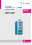
AXIS SWITCH
POSISwitch® AX 5000
for POSIDRIVE® MDS 5000
Mounting and Commissioning Guidelines
Be sure to read and adhere to this mounting and
commissioning instructions before mounting and
commissioning!
MANAGEMENTSYSTEM
certified by DQS according to
DIN EN ISO 9001, DIN EN ISO 14001
Reg-No. 000780 UM/QM
COMMISSIONING
CONNECTION
MOUNTING
SV 5.1
02/2005
POSISwitch® AX 5000
STÖBER
ANTRIEBSTECHNIK
Table of Contents
TABLE OF CONTENTS
1. Notes on Safety
1
2. Technical Data
2.1 Electrical
2.2 Mechanical
2
2
3
3. Mechanical Installation
3.1 Installation Location
3.2 Mounting
4
4
4
4. Electrical Installation
4.1 EMC
4.2 Connection of POSISwitch® to MDS 5000
5
5
5
4.3
4.4
4.5
4.6
Connection of POSISwitch® to Position
Encoder
Connection of Temperature Sensors and
Braking Contacts
Connection of Power and Relays/Contactors
Connection of Motors
5
5
5
5
5. Connection Allocation
5.1 Terminal Overview
5.2 Terminal Allocation
6
6
6
6. Configuration
9
7. Examples
10
8. Accessories
11
STÖBER ANTRIEBSTECHNIK - Germany
12
STÖBER ANTRIEBSTECHNIK - International
14
POSISwitch® AX 5000
STÖBER
ANTRIEBSTECHNIK
1. Notes on Safety
1
NOTES ON SAFETY
Before mounting and commissioning, be sure to read these mounting and commissioning instructions
to prevent the occurrence of avoidable problems during commissioning and/or operation.
®
®
POSISWITCH AX 5000 of the MDS family is a supplemental module for POSIDRIVE of the MDS family. In the
sense of DIN EN 50178 (earlier VDE 0160), it is an electrical resource of power electronics (BLE) for the
regulation of energy flow in high-voltage systems. It is exclusively intended for powering servo machines.
Handling, mounting, operation and maintenance must be performed in adherence to valid regulations and/or
legal specifications, applicable standards and this technical documentation.
This is a restricted marketing class product in accordance with IEC 61800-3. In residential areas, this product
may cause high-frequency interference for which the user may be called on to provide suitable
countermeasures.
Strict adherence to all rules and regulations must be ensured by the user.
The safety notes and specifications contained in further sections (items) must be adhered to by the user.
Caution! High touch voltage! Danger of shock! Hazardous to life!
®
When power is applied, the connections may not become disconnected under any circumstances. POSISwitch
®
AX 5000 may not be opened. Prerequisite for the correct POSISwitch AX 5000 function is the correct
configuration and mounting of the inverter drive. The device may only be transported, installed, commissioned
and controlled by specialized personnel who are qualified for this task.
Pay particular attention to:
• Permissible protection class: Protective ground. Operation is only permitted with regulation connection of
the protective conductor. Direct operation of the devices on IT networks is not possible.
• Installation work may only be performed when the power is disconnected. When work must be performed
on the drive, inhibit the enable of the inverter and disconnect the entire drive from the power network.
(Adhere to the 5 safety rules.)
• Discharge time of the DC link capacitors on the inverter > 5 minutes
• Do not penetrate the inside of the device with any kind of object.
• When performing mounting or any other work in the switching cabinet, protect the device from falling
objects (pieces of wire, leads, metal parts, and so on). Parts with conductive properties can cause a short
circuit on the connections (terminal strips, sockets) and device failure
• Before commissioning, make sure that the plug connectors are positioned correctly and the connections
are secured tightly with screws.
®
POSISwitch AX 5000 must be installed in a switching cabinet in which the maximum ambient temperature is
not exceeded (see technical data). Avoid humidity.
Only copper wires may be used. The line cross sections to be used are listed in table 310-16 of standard NEC
o
o
at 60 C or 75 C.
STÖBER ANTRIEBSTECHNIK GmbH + Co. KG accepts no liability for damages caused by nonadherence to the instructions or the applicable regulations.
The motors must be equipped with integrated temperature monitoring or external motor overload protection
must be used.
®
®
POSISwitch AX 5000 is only certified for operation on POSIDRIVE of the MDS family.
Notes:
Subject to technical changes to improve the devices without prior notice. This documentation is purely
a product description. It is not a promise of properties in the sense of warranty law.
1
POSISwitch® AX 5000
STÖBER
ANTRIEBSTECHNIK
2. Technical Data
2
TECHNICAL DATA
Model key
POSISwitch® AX 5000/4
Designation
Number of axes
5. Generation
2.1
Electrical
Device Type
POSISwitch® AX 5000/4
General
ID no.
44573
Voltage
24 V ±20% (protected against polarity reversal)
Current consumption
(without encoder and contactor)
<100 mA
Ambient temperature
0 – 45 °C
Encoder system
EnDat®
EnDat® Port
Input level
Connection, encoder input
Connection, encoder output
Output level
®
EnDat version
Max. clock pulse frequency
Switchover time
Galvanic isolation
®
®
EnDat input to EnDat input
Galvanic isolation
®
EnDat input to 24 V supply
Max. cable length between
®
POSISwitch and inverter
Max. cable length between
POSISwitch® and encoder
TIA/EIA 485 / 422
Sub D 15-pole (STÖBER contact allocation)
SUB D 15-pin
(STÖBER contact allocation – see connection cable in chap. 8)
TIA/EIA 485
EnDat® 2.1
2 MHz
< 200 µsec
No
500 V
80 m
1
20 m
1
Voltage for encoder
5.25 V
Max. output current for encoder
200 mA
Power protection
Number of protective connections
Max. output current
Output voltage
Connection
Galvanic isolation to EnDat®
1
Only valid in connection with STÖBER cables
2
4
800 mA (limitation 900 mA)
min. 22 V at 600 mA
Screw-type terminal (max. 1.5 mm²)
Yes
POSISwitch® AX 5000
STÖBER
ANTRIEBSTECHNIK
2. Technical Data
2.2
Mechanical
Specifications in mm
70
35
Ø6
159
179
10
45
6
3
POSISwitch® AX 5000
STÖBER
ANTRIEBSTECHNIK
3. Mechanical Installation
3
MECHANICAL INSTALLATION
This chapter gives you complete information on the subject of mechanical installation.
Only specialized personnel qualified for this task may install, commission and control the device.
3.1
Installation Location
• Operate only in closed switching cabinet.
• Avoid installation above heat-generating devices.
• Ensure sufficient air circulation in the switching cabinet.
®
(The installation site of POSISwitch AX 5000 may not hinder the air circulation of the inverter.)
• The installation site must be free of dust, corrosive fumes and all liquids (in accordance with soil degree 2 as per EN 60204 /
EN 50178).
• Avoid humidity.
• Avoid condensation (e.g., due to anti-condensation heaters).
• To satisfy EMC requirements, use mounting plates with conductive surfaces (e.g., unpainted).
3.2
Mounting
Possible arrangement
Approx.
15 to 20 mm
Max. of 80 m1
Encoder 1 to 4
Drilling jig
POSISwitch® connection cable
Encoder 1 to 4
Length: 500 mm (ID no. 45405)
Length: 2500 mm (ID no. 45386)
_____________________________
1
Valid only in connection with STÖBER cables
4
POSISwitch® AX 5000
STÖBER
ANTRIEBSTECHNIK
4. Electrical Installation
4
ELECTRICAL INSTALLATION
This chapter gives you complete information on the subject of electrical installation.
Only specialized personnel qualified for this task may install, commission and control the device.
4.1
EMC
This chapter gives you general information on EMC-suitable installation. These are only recommendations. Depending on the
application, the ambient conditions and the legal requirements, measures in addition to the following recommendations may be
necessary.
• Mount device on conductive surface (unpainted).
• Motor cables must be installed in separate space from the encoder cables.
• Use only shielded cables for motor and encoder lines (corresponding cabels can be ordered from STÖBER
ANTRIEBSTECHNIK.).
• Apply shield of the motor cable on both sides.
• The circuit breakers may not interrupt the shield lines.
• Output derating must be used for motor lines > 50 m.
• When an additional transmission plug connector is installed in the motor cable, the shield may not be interrupted and the plug
connection may not be opened when the motor is electrified.
• When the braking line is installed in the motor cable, the braking line must be shielded separately.
4.2
Connection of POSI Switch® AX 5000 to MDS 5000
POSISwitch® AX 5000 is controlled by POSIDRIVE® MDS 5000. A connection via socket X4 on the MDS 5000 to plug X500 on
the AX 5000 enables the switching of the axes. Completely prefabricated cables are available in the lengths 500 mm (ID no.
45405) and 2500 mm (ID no. 45386). Cf. chap. 8.
POSISwitch® AX 5000 is usually installed in the immediate vicinity of the inverter (see chap. 3.1 and 3.2). However, if this is not
possible or desirable, a cable of up to 80 m1 in length can be used.
4.3
Connection of POSI Switch® AX 5000 to Position Encoder
The encoders of the individual servo motors are connected to POSISwitch® AX 5000 with the normal STÖBER encoder cable.
The encoder of the first motor is connected with the socket Enc. 1. The encoder of the second motor is connected with the
socket Enc. 2 and so on.
The length of the encoder cable may not exceed 20 m1.
4.4
Connection of Temperature Sensors and Braking Contacts
Activation of a halting brake and the evaluation of the temperature sensors on the motors is handled with braking module for 24
V brake (BRM 5000). The brakes or temperature sensors (positor lines) allocated to the motors are activated and deactivated
via auxiliary contacts of the applicable power relays/contactors. Chapter 7 contains examples of correct wiring.
4.5
Connection of Power and Relays/Contactors
POSISwitch® AX 5000 is powered with 24 V via the screw-type terminal strip X501 (terminals 1 and 2). Power consumption is a
maximum of 1 A. The power relays/contactors are controlled via the AX 5000 on terminals X501.6 to X501.9. The contactors are
powered via terminals X501.4 and X501.5. Chapter 7 contains examples of correct wiring.
4.6
Connection of Motors
The motors are activated and deactivated via power relays/contactors. POSISwitch® AX 5000 controls and checks the power
relays/contactors. Chapter 7 contains examples of correct wiring.
Please adhere to the EMC recommendations.
Use to switch the motor temperature sensor relay contacts for low currents/voltages (gold contacts).
1
Only valid in connection with STÖBER cables
5
POSISwitch® AX 5000
STÖBER
ANTRIEBSTECHNIK
5. Connection Allocation
5
CONNECTION ALLOCATION
This section explains the position, designation and allocation of the terminals.
5.1
Terminal Overview
X500
Connection for the
POSIDRIVE® MDS 5000
Enc.
Enc.
Enc.
Enc.
1
2
3
4
Connection for
encoders 1 - 4
X501 Power & relays
5.2
Terminal Allocation
This section presents and describes all interfaces. The exact position is given in chap. 5.1.
X500 – connection for POSIDRIVE® MDS 5000
PIN11
8
1
1
15
9
Signal / Function
Description
1
NC
Not connected
2
GND
Reference potential
Digital ground
3
NC
Not connected
4
VCC
Power supply 5 VDC
Is jumpered internally with pin 12
5
DATA+
Differential input / output
For data signal
6
NC
Not connected
ERROR+
Differential output
For error signal
7
8
CLK+
Differential input
For clock pulse signal
9
NC
Not connected
10
NC
Not connected
11
NC
Not connected
12
Sense
Sense connection
Is jumpered internally with pin 4
13
DATA-
Differential input / output (inverse)
For data signal
14
ERROR-
Differential output (inverse)
For error signal
15
CLK -
Differential input (inverse)
For clock pulse signal
View of terminal/sub D
6
Circuiting
POSISwitch® cable
1
1
9
9
10
10
11
11
12
12
13
13
14
14
15
15
2
2
3
3
4
4
5
6
7
8
5
6
7
8
POSISwitch
X500
®
POSISwitch® AX 5000
STÖBER
ANTRIEBSTECHNIK
5. Connection Allocation
X501 – voltage supply and relays
PIN1
Signal / Function
Description
Circuiting
Voltage supply
1
1
+24VDC
2
0V
3
PE
4
K+
5
K-
6
K1 OUT
7
K2 OUT
8
K3 OUT
9
K4 OUT
®
Powers POSISwitch AX 5000 and the
motor encoder
Reference potential
For voltage supply / PIN 1
Protective conductor
Connection to housing
Power for the relays
+ Potential for powering power
relays/contactors
Umin = 5 V; Umax = 30 V
Reference potential
For terminal 4
Relay output 1
For first axis
Imax with 24 V = 0.5 A
Internal safety circuit with free-wheeling
diode for relay coil.
Relay output 2
For second axis
Imax with 24 V = 0.5 A
Internal safety circuit with free-wheeling
diode for relay coil.
Relay output 3
For third axis
Imax with 24 V = 0.5 A
Internal safety circuit with free-wheeling
diode for relay coil.
Relay output 4
For fourth axis
Imax with 24 V = 0.5 A
Internal safety circuit with free-wheeling
diode for relay coil.
View of terminal/sub D
7
POSISwitch® AX 5000
STÖBER
ANTRIEBSTECHNIK
5. Connection Allocation
Enc. 1; Enc. 2; Enc 3; Enc. 4 – connection for encoders 1 - 4
PIN1
Signal / Function
Description
Circuiting
1
NC
Not connected
2
GND
Reference potential
Digital ground
3
NC
Not connected
4
VCC
Power supply 5 VDC
Is jumpered internally with pin 12
5
DATA+
Differential input / output
For data signal
6
NC
Not connected
7
NC
Not connected
8
CLK+
Differential output
For clock pulse signal
9
NC
Not connected
10
NC
Not connected
11
NC
Not connected
12
Sense
Sense connection
Is jumpered internally with pin 4
13
DATA-
Differential input / output (inverse)
For data signal
14
NC
Not connected
15
CLK -
Differential output (inverse)
For clock pulse signal
Connection of the encoder to POSI Switch® AX 5000
Signal
1
Clock+ Sense DATA- DATA+ Clock-
UB+
DGND
9
2
Enc. 1-4
10
*
3
11
4
12
5
13
2
rs
rs
*
6
14
7
15
8
*
Terminal, enc. 1 to 4 on
®
POSISwitch
1
View of terminal/sub D
8
1
2
9
10
12
11
3
4
8
12
13
5
15
4
2
Motor
1
2
5
6
8
12
10
Cable²
ge
rs
br
ws
gn
rt
bl
8
7
6
5
1
1) PIN number of 12-pin encoder plug for STÖBER ED/EK motor
2) Color when STÖBER encoder cable is used
ge = yellow, rs = pink, br = brown, ws = white, gn = green, rt = red, bl = blue
* Cables twisted in pairs
Encoder connection
Bracket flange socket
motor
POSISwitch® AX 5000
STÖBER
ANTRIEBSTECHNIK
6. Configuration
6
CONFIGURATION
This chapter describes the configuration of POSISwitch® AX 5000.
®
The user decides whether POSISwitch will be used in the configuration assistants during the step “inverter selection”. An
appropriate selection is offered here (see figure).
®
When POSISwitch AX 5000 is configured, the device is adjusted to the application via the following parameters.
Fieldbus
Address
Par.
Description
F90
Release time axis-switch: Specifies the release time of the contactor used for the axis
switchover. This minimum time is waited before the inverter lets the next contactor be applied.
Value range in msec: 0 ... 20 ... 32767
Global
r=2, w=3
F91
Global
r=2, w=3
2A5Ah
0h
2A5Bh
0h
2E08h
0h
2E12h
0h
480Ch
0h
Fieldbus: 1LSB=1·msec; type: I16; ; USS address: 06 16 80 00 hex
Set time axis-switch: Specifies the set time of the contactor used for the axis switchover. This
time is at least waited before the inverter lets the axis be electrified.
Value range in msec: 0 ... 20 ... 32767
Fieldbus: 1LSB=1·msec; type: I16; ; USS address: 06 16 C0 00 hex
PosiSwitch® encoder selector: Available as an option, the POSISwitch® control module
permits the connection of several motors to one inverter. In H08 it can be set separately for each of
Achse, OFF the four (software) axes which connection on the POSISwitch® (i.e., which motor) is allocated to
the particular axis configuration. This routine permits two or more applications to be run together on
r=2, w=2
separate (software) axes with a single motor.
H08
Note: Following a change in parameter H08, correct evaluation of the electronic nameplate is not
ensured until after a device new start.
0: Enc1;
1: Enc2;
2: Enc3;
3: Enc4;
Field bus: 1LSB=1; Typ: U8; USS-Adr: 08 02 00 00 hex
1 Only when a POSISwitch® was detected on X4.
H18
Global, OFF
Posi-switch® port-status: Indicates as a binary word the POSISwitch® ports to which
encoders are connected. This is determined by the inverter during startup.
Fieldbus: 1LSB=1·; type: U8; ; USS address: 08 04 80 00 hex
read (2)
1 Only when a POSISwitch® was detected on X4
U12
Level motor connection: When the axis switch via POSISwitch® is utilized, the inverter can
test during switching whether the contactor of the motor to be switched off has actually broken
contact (opened). In addition, under certain circumstances, it can be determined that no motor is
connected.
0: inactive
3: fault
Global
r=3, w=3
Fieldbus: 1LSB=1·; type: U8; ; USS address: 15 03 00 00 hex
9
POSISwitch® AX 5000
STÖBER
ANTRIEBSTECHNIK
7. Examples
7
EXAMPLES
7.1
Principal Circuit Diagram (without Shielding)
4
3
2
1
5
6
7
8
X10
X2
X302
®
ϑ M1
BRM 5000
L1
L2
L3
PE
POSIDRIVE MDS 5000
L1
L2
L3
PE
X300
K2
K1
4
3
1
K1
X301
Brake
M2
ϑ M4
K4
K3
Brake
M3
K4
Brake
M4
_
U
V
W
PE
X20
K1
K2
M1
X500
K3
K4
M3
M2
M4
15
15
15
15
Enc. 1
Enc. 2
Enc. 3
Enc. 4
POSISwitch AX 5000
®
X501
X4
1 2 3 4 5
6
K1
10
K3
K2
Brake
M1
ϑ M3
+
1
. 15
.
.
15
PE
24V
0V
ϑ M2
7
K2
8
K3
9
K4
POSISwitch® AX 5000
STÖBER
ANTRIEBSTECHNIK
8. Accessories
8
ACCESSORIES
ID No. Designation
Remarks
45405 POSISwitch® connection cable (0.5 m)
Chap. 3
®
Connection cable POSISwitch AX 5000
to POSIDRIVE® MDS 5000
Length: 0.5 m (fabricated)
45386 POSISwitch® connection cable (2.5 m)
Chap. 3
®
Connection cable POSISwitch AX 5000
®
to POSIDRIVE MDS 5000
Length: 2.5 m (fabricated)
44989 Product CD " STÖBER ELECTRONICS 5000"
This CD-ROM contains:
Download POSITool
Also via: http://www.stoeber.de
• POSITool (PC program for programming,
operator control and monitoring of the inverter)
• Documentation
• Fieldbus files
11
STÖBER ANTRIEBSTECHNIK - Deutschland
STÖBER ANTRIEBSTECHNIK
Hauptverwaltung:
STÖBER ANTRIEBSTECHNIK GmbH & Co. KG
Postfach 910103
75091 Pforzheim
Fon
Fax
eMail
07231 582-0
07231 582-1000
[email protected]
Kieselbronner Straße 12
75177 Pforzheim
24-Stunden-Service-Nr.
0180 5 786323
Vanity-No:
0180 5 STOEBER
Vertriebsgebiet Nordwest:
Zentrale
STÖBER ANTRIEBSTECHNIK GmbH & Co. KG
Friedrich-Ebert-Str. 85
58454 Witten
Fon
Fax
eMail
02302 98494-0
02302 98494-50
[email protected]
Zugehörige Technische Büros:
Norddeutschland
20000 - 23919
24000 - 29999
STÖBER ANTRIEBSTECHNIK GmbH & Co. KG
Stefan Hildebrandt
Bei den roten Höfen 4
21698 Harsefeld
Fon
Fax
eMail
04164 811904
04164 811905
[email protected]
Münster
33000 - 33599
33600 - 33899
33900 - 33999
48000 - 49999
59200 - 59329
59470 - 59699
STÖBER ANTRIEBSTECHNIK GmbH & Co. KG
Markus Merker
Grottenkamp 28
48565 Steinfurt
Fon
Fax
eMail
02552 610271
02552 610272
[email protected]
Dortmund West
40000 - 41999
46000 - 47999
50000 - 50999
52000 - 53999
STÖBER ANTRIEBSTECHNIK GmbH & Co. KG
Jürgen Volkmuth
Friedrich-Ebert-Str. 85
58454 Witten
Fon
Fax
eMail
02302 98494-0
02302 98494-50
[email protected]
Dortmund Ost
42000 - 45999
51000 - 51999
57000 - 59199
59330 - 59469
59700 - 59999
STÖBER ANTRIEBSTECHNIK GmbH & Co. KG
Detlef Mock
Friedrich-Ebert-Str. 85
58454 Witten
Fon
Fax
eMail
02302 98494-0
02302 98494-50
[email protected]
Hannover
30000 - 32999
34330 - 34549
37000 - 37199
37400 - 38799
STÖBER ANTRIEBSTECHNIK GmbH & Co. KG
Arne Hülsmeier
Holbeinstraße 43
49525 Lengerich
Fon
Fax
eMail
05481 903946
05481 903974
[email protected]
STÖBER ANTRIEBSTECHNIK GmbH & Co. KG
Postfach 910103, 75091 Pforzheim
Kieselbronner Straße 12, 75177 Pforzheim
Fon
Fax
eMail
07231 582-0
07231 582-1000
[email protected]
Vertriebsgebiet Mitte:
Zentrale
Zugehörige Technische Büros:
Saar-Pfalz
54000 - 56999
65000 - 66919
67200 - 67319
67500 - 67999
STÖBER ANTRIEBSTECHNIK GmbH & Co. KG
Roland Dillmann
Black & Decker-Str. 1
65510 Idstein
Fon
Fax
eMail
06126 989406
06126 55499
[email protected]
Wiesbaden
34000 - 34329
34550 - 36399
37200 - 37299
60000 - 64999
STÖBER ANTRIEBSTECHNIK GmbH & Co. KG
Jens Thomas
Black & Decker-Str. 1
65510 Idstein
Fon
Fax
eMail
06126 989405
06126 55499
[email protected]
STÖBER ANTRIEBSTECHNIK GmbH & Co. KG
Postfach 910103, 75091 Pforzheim
Kieselbronner Straße 12, 75177 Pforzheim
Fon
Fax
eMail
07231 582-0
07231 582-1000
[email protected]
Vertriebsgebiet Süd:
Zentrale
Stand: 06.05.2004
STÖBER ANTRIEBSTECHNIK - Deutschland
STÖBER ANTRIEBSTECHNIK
Zugehörige Technische Büros:
Pforzheim Süd
71000 - 71299
75100 - 75399
STÖBER ANTRIEBSTECHNIK GmbH & Co. KG
Günter Großmann
Postfach 910103, 75091 Pforzheim
Kieselbronner Straße 12, 75177 Pforzheim
Fon
Fax
eMail
07231 582-1229
07231 582-1349
[email protected]
Pforzheim Nord
70000 - 70999
71300 - 71499
71600 - 71999
74000 - 74172
74300 - 74399
75400 - 75999
STÖBER ANTRIEBSTECHNIK GmbH & Co. KG
Philipp Gerstner
Postfach 910103, 75091 Pforzheim
Kieselbronner Straße 12, 75177 Pforzheim
Fon
Fax
eMail
07231 582-1217
07231 582-1349
[email protected]
Nordbaden
66920 - 67199
67320 - 67499
68000 - 69999
74173 - 74299
74600 - 75099
76600 - 76999
97860 - 97999
STÖBER ANTRIEBSTECHNIK GmbH & Co. KG
Stefan Rotterdam
Postfach 910103, 75091 Pforzheim
Kieselbronner Straße 12, 75177 Pforzheim
Fon
Fax
eMail
07231 582-1149
07231 582-1349
[email protected]
Südbaden
72190 - 72299
76000 - 76599
77000 - 77999
78090 - 78149
79000 - 79999
STÖBER ANTRIEBSTECHNIK GmbH & Co. KG
Daniel Lohse
Postfach 910103, 75091 Pforzheim
Kieselbronner Straße 12, 75177 Pforzheim
Fon
Fax
eMail
07231 582-1114
07231 582-1349
[email protected]
Reutlingen
72000 - 72189
72300 - 72999
78000 - 78089
78150 - 78999
88000 - 89299
89570 - 89999
STÖBER ANTRIEBSTECHNIK GmbH & Co. KG
Wilhelm Haydt
Gerh.-Hauptmann-Str. 53
72793 Pfullingen
Fon
Fax
eMail
07121 994035
07121 994036
[email protected]
Württemberg Nord-Ost
71500 - 71599
73000 - 73999
74400 - 74599
89500 - 89569
STÖBER ANTRIEBSTECHNIK GmbH & Co. KG
Klaus Buschko
Meisenweg 25
72589 Westerheim
Fon
Fax
eMail
07333 950773
07333 950774
[email protected]
München
80000 - 84999
85200 - 87999
89300 - 89499
94000 - 94999
STÖBER ANTRIEBSTECHNIK GmbH & Co. KG
Udo Cyrol
Industriestraße 20 a
91353 Hausen
Fon
Fax
eMail
09191 616890
09191 734538
[email protected]
Nürnberg
85000 - 85199
90000 - 93999
95000 - 96499
97000 - 97859
STÖBER ANTRIEBSTECHNIK GmbH & Co. KG
Wolfgang Lukas
Industriestraße 20 a
91353 Hausen
Fon
Fax
eMail
09191 734537
09191 734538
[email protected]
STÖBER ANTRIEBSTECHNIK GmbH & Co. KG
Postfach 910103, 75091 Pforzheim
Kieselbronner Straße 12, 75177 Pforzheim
Fon
Fax
eMail
07231 582-0
07231 582-1000
[email protected]
Vertriebsgebiet Ost:
Zentrale
Zugehörige Technische Büros:
Berlin / Brandenburg
06000 - 06599
06730 - 07299
10000 - 19999
23920 - 23999
38800 - 39999
STÖBER ANTRIEBSTECHNIK GmbH & Co. KG
Bernd Weise
Werneuchener Weg 9
15345 Altlandsberg
Fon
Fax
eMail
033438 5731
033438 5732
[email protected]
Lichtenstein
00000 - 05999
06600 - 06729
07300 - 09999
36400 - 36999
37300 - 37399
96500 - 96999
98000 - 99999
STÖBER ANTRIEBSTECHNIK GmbH & Co. KG
Jürgen Stolper
Günsbacher Straße 4
09350 Lichtenstein
Fon
Fax
eMail
037204 2985
037204 2986
[email protected]
Stand: 06.05.2004
STÖBER ANTRIEBSTECHNIK - International
STÖBER ANTRIEBSTECHNIK
Austria
STÖBER ANTRIEBSTECHNIK GmbH
Fabriksplatz 1
4662 Steyrermühl
Phone +43 7613 76000
Fax
+43 7613 76009
eMail [email protected]
France
STÖBER S.a.r.l.
47, rue Maurice Flandin
69003 Lyon
Phone +33 4 72132438
Fax
+33 4 72132457
eMail [email protected]
Great Britain
STOBER DRIVES LTD.
Unit 9, Abbeymead Industrial Park
Brooker Road, Waltham Abbey
Essex EN9 1HU
Phone +44 1992 709710
Fax
+44 1992 714111
eMail [email protected]
Italy
STÖBER TRASMISSIONI S. r. l.
Via Risorgimento, 8
20017 Mazzo di Rho (Milano)
Phone +39 02 93909-570
Fax
+39 02 93909-325
eMail [email protected]
Korea
DAE KWANG STOEBER CO. LTD.
2 Ma 301-3 Sihwa Industrial Complex,
1704-3 Jungwang dong, Siheung city,
Gyunggi do, Korea
Postcode 429-845
Phone +82 31 4347047
Fax
+82 31 4347048
eMail [email protected]
Poland
STOEBER POLSKA
ul.H.Kamienskiego 201-219
51-126 Wroclaw
Phone +48 71 3207417
Fax
+48 71 3207417
eMail [email protected]
USA
STOBER DRIVES INC.
1781 Downing Drive
Maysville, KY 41056
Phone +1 606 7595090
Fax
+1 606 7595045
eMail [email protected]
Belgium
VAN DOREN - PILLE N. V.
Industrieterrein De Prijkels
Venecoweg 25
9810 Nazareth
Phone +32 9 2521309
Fax
+32 9 2522374
eMail [email protected]
Brasil
FRAPHE INDUSTRIA E COMERCIO
Rua Bairro Da Ponte Alta S/N
37640-000 Extrema - MG
Phone +55 35 34355965
Fax
+55 35 34353887
eMail [email protected]
Bulgaria
Z & M PRIVATE COMPANY
5, Angel Kantchev Str.
1000 Sofia
Phone +359 2 9865855
Fax
+359 2 9865916
eMail [email protected]
China
WK-INTERSALES BEIJING
German Centre
Unit 0525-0530, Landmark Tower 2
8 North Dongsanhuan Road
Chaoyang District
Beijing 100004
Phone +86 10 65906425 + 26
Fax
+86 10 65906785
eMail [email protected]
Colombia
SOCOMEX LTDA.
Apdo. Aereo 11606
Santafe de Bogota D. C.
Phone +57 2856105 / +57 2856496
+57 2856336
Fax
+57 13350487
Denmark
EEGHOLM A/S
Grundtvigs Allé 165-169
P. O. Box 190
6400 Sønderborg
Phone +45 73 121212
Fax
+45 73 121213
eMail [email protected]
Stand: 19.07.2004
STÖBER ANTRIEBSTECHNIK - International
STÖBER ANTRIEBSTECHNIK
Finland
EIE MASKIN OY
PL 80
10600 Tammisaari
Phone +358 19 2461642
Fax
+358 19 2461643
eMail [email protected]
Hungary
BDI Hungary Ltd.
Fóti Street 141, Bldg 37.
1046 Budapest
Phone +36 1 2311010
Fax
+36 1 2311030
eMail [email protected]
the Netherlands
MIJNSBERGEN B. V.
Postbus 166
3640 AD Mijdrecht
Phone +31 297 285821
Fax
+31 297 272326
eMail [email protected]
Norway
ELMEKO AS
Postbox 80
1306 Baerum Postterminal
Phone +47 67 572270
Fax
+47 67 572280
eMail [email protected]
Peru
POWERMATIC S. A.
Av. Los Ingenieros 333
Ate-Vitarte, Lima 3
Phone +51 1 3490184 / 3494011
Fax
+51 1 4370073
eMail [email protected]
Philippines
LEELENG COMMERCIAL, INC.
387 - 393 Dasmariñas St.
P. O. Box 480
Manila
Phone +63 2 2418901 to 05
Fax
+63 2 2414060
eMail [email protected]
South Africa
BEARING MAN LTD.
P. O. Box 33431
Jeppestown 2043
Phone +27 11 6201500
Fax
+27 11 6201775
eMail sales@bearing_man.co.za
Spain
TAHFER COMERCIAL, S. A.
Jesus, 27
28917 - LA FORTUNA
Phone +34 91 6193424
Fax
+34 91 6197792
eMail [email protected]
S.p.i.t. KOOM s. I.
Camino Caserio Parada, 25
20015 San Sebastián
Phone +34 94 3297809
Fax
+34 94 3297810
eMail [email protected]
Sweden
EIE MASKIN AB
Postfach 7
12421 Bandhagen
Phone +46 8 7278800
Fax
+46 8 7278899
eMail [email protected]
Switzerland
INDUR ANTRIEBSTECHNIK AG
Margarethenstraße 87
4008 Basel
Phone +41 61 2792900
Fax
+41 61 2792910
eMail [email protected]
Thailand
GERMAN ENGINEERING &
MACHINERY CO., LTD.
399 Moo 17 Bangna Trad Rd. Km 23
Bangsaothong Sub District
10540 Samutprakarn
Phone +66 2 3153331 / 3153332
Fax
+66 2 3153663
eMail [email protected]
Turkey
HARTEK Sanayigi Ticaret Ltd. Sti
Y. Dudullu Mah. Alptekin
Sk. No: 2 Kat: 2
Phone +90 216 5406026
Fax
+90 216 5406030
eMail [email protected]
34775 ÜMRANIYE - ISTANBUL
Stand: 19.07.2004
Additional information under:
Presented by:
STÖBER ANTRIEBSTECHNIK
GERMANY
GmbH + Co. KG
Kieselbronner Strasse 12 · 75177 Pforzheim
Postfach 910103 · 75091 Pforzheim
Fon +49 (0) 7231 582-0, Fax +49 (0) 7231 582-1000
Internet: http://www.stoeber.de / e-mail: [email protected]
- Subject to technical change without prior notice -
STÖBER . . . The Drive for your Automation
© 2005 STÖBER ANTRIEBSTECHNIK GmbH + Co. KG
Publication no. 441689.00.03 · 02.2005
http://www.stoeber.de