1
™
WorkingPr o Series
BASS AMPLIFIERS
.
Important Safety Instructions
This symbol warns the user of dangerous voltage levels
localized within the enclosure.
This symbol advises the user to read all accompanying
literature for safe operation of the unit.
∆ Read, retain, and follow all instructions. Heed all warnings.
∆ Only connect the power supply cord to an earth grounded AC
receptacle in accordance with the voltage and frequency ratings
listed under INPUT POWER on the rear panel of this product.
∆ WARNING: To prevent damage, fire or shock hazard, do not
expose this unit to rain or moisture.
∆ Unplug the power supply cord before cleaning the unit exterior
(use a damp cloth only). Wait until the unit is completely dry
before reconnecting it to power.
∆ Maintain at least 6 inches (15.25 cm)of unobstructed air space
behind the unit to allow for proper ventilation and cooling of the
unit.
∆ This product should be located away from heat sources such as
radiators, heat registers, or other products that produce heat.
∆ This product may be equipped with a polarized plug (one blade
wider than the other). This is a safety feature. If you are unable
to insert the plug into the outlet, contact an electrician to replace
your obsolete outlet. Do not defeat the safety purpose of this
plug.
∆ Protect the power supply cord from being pinched or abraded.
∆ This product should only be used with a cart or stand that is
recommended by the manufacturer.
∆ The power supply cord of this product should be unplugged from
the outlet when left unused for a long period of time, or during
electrical storms.
∆ This product should be serviced by qualified service personnel
when: the power supply cord or the plug has been damaged; or
objects have fallen, or liquid has been spilled onto the product;
or the product has been exposed to rain; or the product does not
appear to operate normally or exhibits a marked change in
performance; or the product has been dropped, or the enclosure
damaged.
∆ Do not drip nor splash liquids, nor place liquid filled containers
on the unit.
∆ CAUTION: No user serviceable parts inside, refer servicing to
qualified personnel only.
∆ SWR® amplifiers and loudspeaker systems are capable of
producing very high sound pressure levels which may cause
temporary or permanent hearing damage. Use care when
setting and adjusting volume levels during use.
∆ Hazardous voltages may be present within the cabinet even when
the power switch is off and the power cord is connected.
Therefore, disconnect the power cord from the rear panel power
inlet before servicing. The power inlet must remain readily
operable.
4
S W R ® Wo r k i n g P r o ™ B a s s A m p l i f i e r s
Congratulations on your purchase of an SWR®
WorkingPro™ amplifier! You now own a feature-packed,
professional-quality SWR® bass amplifier, with the famous
SWR® tone, power, clarity, and true full-range response
that’s made SWR® the choice of professionals for over
twenty years.
Whether you’ve chosen the WorkingPro™ 400 or 700,
each model in the WorkingPro™ series combines the best
classic SWR® features:
• The famous preamp designed by original engineer
Steve W. Rabe
• The Aural Enhancer
• The 4-band active EQ with variable midrange – with
exciting new features, like the footswitchable tuning
mute
• More flexibility with the XLR output
• And especially, the new, exclusive Bass Intensifier
circuit, which simultaneously boosts and compresses
a set of chosen frequencies to add pure low-end
thickness to your bass sound
SWR®, since its founding in 1984, was created to serve
one purpose – to provide bass amplification products with
professional quality, tone, features and power delivery for
players of all levels and styles. We sincerely thank you for
choosing SWR®, and remain committed to helping you
Amplify Your Future™.
Read through this Owner’s Manual before using your
amplifier not only to ensure your safety and protect your
investment, but so the full potential of the SWR®
WorkingPro™ is at your command!
Please verify that the following items were included in your
SWR® WorkingPro™ packaging: AC Cable, Dual
Footswitch, SWR® Catalog.
Front Panel
A. INPUT - Plug your bass into this jack using a shielded
instrument cable.
B. INPUT PAD - Reduces input sensitivity to allow
cleaner response with high-output (above 1-Volt RMS)
guitars. Use the setting that sounds best!
NORMAL—Full input sensitivity
–10dB PAD—Lower input sensitivity
Active (pre-amplified) bass guitars—if you hear
distortion even with the INPUT PAD switch active and
a low (not clipping) GAIN {D} setting, try replacing your
guitar battery.
C. MUTE - Disables all audio output except the TUNER
OUT {V} and HEADPHONES {R} jacks. Useful when
tuning up, during instrument changes or while using
headphones. The LED
indicates MUTE is on.
✧
D. GAIN - Adjusts the volume level of the preamp
section. After you adjust any tone or effects levels, use
the PRE AMP CLIP LED to find the best GAIN setting
for the optimal signal–to–noise ratio:
PRE AMP CLIP - Indicates when the preamp, tone
circuits or output buffer are being overdriven (clipping)
causing signal distortion. Occasional flashing is
normal at your instrument’s peak output levels. The
type of clipping that this LED indicates is not harmful
to your amplifier, so reduce GAIN if you hear unwanted
distortion while this LED is on. NOTE: If an effects
device is overdriven by the output level of the
EFFECTS SEND {S} jack, reduce GAIN, then increase
MASTER Volume {M} to adjust the overall loudness of
the amplifier.
s w r s o u n d . c o m
✧
F r o n t P a n e l —continued
E. AURAL ENHANCER - Featured on just about every
SWR® amplifier since the company’s inception in
1984, it is a trademark part of the “SWR Sound”
people have come to know and love. It was developed
to bring out the fundamental low notes of the bass
guitar, enhance the high-end transients, and reduce
certain frequencies that “mask” the fundamentals.
The ultimate results are: 1. A more transparent sound,
especially noticeable when slapping and popping, and
2. Passive basses take on an “active” type of quality
when set at “2 o’clock” or positions further clockwise.
G.
Most significantly for basses, the AURAL ENHANCER
will help bring out the fundamentals of your lower
registers without masking them with overtones, as is
possible when using the BASS control only. At the
same time, it opens up the sibilance characteristics of
all instruments without being harsh.
MIDRANGE SEMI-PARAMETRIC EQ You have two midrange tone controls.
MID LEVEL boosts or cuts (±15dB) the
level of midrange response at the specific
midrange frequency selected by the
MID FREQ knob. To find a midrange
frequency, rotate MID LEVEL fully to either “–15” or
“+15” (this makes frequency changes more
noticeable). Adjust MID FREQ to the specific
frequency, then adjust MID LEVEL as desired.
NOTE: When MID LEVEL is in the center (12 o’clock)
position, the midrange semi-parametric equalizer is
“flat” and has no effect on your signal regardless of
the position of the MID FREQ control.
How the AURAL ENHANCER works: Think of it as a
variable tone curve that changes depending on where
you set the AURAL ENHANCER control knob. As you
rotate the control clockwise from the “MIN” position,
you are elevating low–, mid–, and high–frequency
points selected specifically because they’re different
than those of the individual Tone Controls.
This remains true up to about the “2 o’clock” position.
This position—a favorite for many users—brings out
both the low end fundamentals and crisp highs and, at
the same time, adds a little lower midrange to help cut
through the band. However, if you go further
clockwise and past the “2 o’clock” position, selected
mids will start to drop off—specifically, a group of
frequencies centered around 200 Hz. At this point and
after, the effect becomes much more pronounced.
However, the curves involved here are gentle, as
opposed to the very extreme curves you can create by
boosting or cutting the Active Tone Controls (EQ).
TIPS: If you need to “cut through” the band a little
more, try boosting the 200–400Hz midrange
frequency level. If you like a more transparent or
“scooped” sound, try cutting the 800Hz midrange
frequency level. The midrange controls are especially
useful in controlling fretless basses and their inherent
qualities.
H. TREBLE - Employs a shelving-type circuit that boosts
or cuts high-frequencies (and their subsequent
octaves ±15dB) from about 2 kHz to 14 kHz.
I.
TRANSPARENCY - Boosts or cuts ultra-high
frequencies (±15dB) above ~5kHz.
J. EFX BLEND - Controls how apparent your effects
loop sounds, or more precisely, the ratio of external
effects loop (wet) signal, to internal amplifier (dry)
signal. Used in conjunction with the rear panel Effects
Loop jacks, EFX BLEND is enabled when a 1/4" phone
plug is inserted into EFFECTS RETURN {S}.
Your ears are the best judge when it comes to settings
that affect the tone of your instrument. Obviously,
“numbers, curves and circuits” mean nothing if not
heard with your own ears. So, play a chord, a
repeated lick, or a harmonic, and turn the AURAL
ENHANCER control to various points on the knob to
hear the effect for yourself.
F.
BASS - Employs a shelving-type circuit that boosts or
cuts low-frequencies (±15dB), from about 30Hz to
100Hz, centered at around 80Hz.
✧
5
s w r s o u n d . c o m
✧
6
F r o n t P a n e l —continued
K. BASS INTENSIFIER - A new SWR® tone circuit that
boosts of a chosen set of low-frequencies combined
with a smooth, fast-acting compressor. The boost and
compression work in harmony to allow radical boosts
in the chosen bass and lower midrange frequencies
without the side-effect of overdriving the amplifier
circuitry. Once dialed in, it literally intensifies the bass
tone in your sound. It can be used as a boost for
certain, heavier sections of a tune, or just as a part of
your overall preferred sound.
ENGAGE - Activates the BASS INTENSIFIER circuit
as indicated by the LED .
LEVEL - Adjusts the amount of bass boost added by
the BASS INTENSIFIER. Hint: Adjust slowly, so you
can hear the difference a small amount of this effect
can have on your tone.
CUTOFF - Adjusts the frequency range boosted by
the BASS INTENSIFIER. When fully counterclockwise, only frequencies below ~80Hz are
affected. When fully clockwise, frequencies below
~200Hz are affected.
To best hear what this control does: 1. Decrease
MASTER Volume to half its normal setting (or less).
2. Set LEVEL to maximum. 3. Set CUTOFF to 80Hz.
4. Play a note repeatedly (low ‘E’ or low ‘A’) and slowly
rotate CUTOFF clockwise. You will hear additional
frequencies being boosted as you turn the dial, and
the overall effect will seem louder because more
frequencies are being boosted. As always, your ears
are the best judge. Take some time to experiment and
hear what works best.
✧
L. LIMITER - This circuit is located after MASTER
Volume and before the power amplifier in the signal
path. Therefore, the circuit is driven by MASTER
Volume. Its threshold (starting point) is preset so you
get the maximum overall apparent volume without
overdriving the power amplifier or internal speakers.
DEFEAT - Disables the internal LIMITER circuitry:
LIMITER ON
LIMITER OFF (DEFEATED)
ACTIVE - Indicates exactly when the LIMITER circuit
is working—only when the LIMITER is ON.
POWER AMP CLIP - Indicates when the power amp
is being overdriven (clipping) causing signal distortion.
Unlike preamp clipping, power amp clipping can be
harmful to your equipment. Therefore, if the POWER
AMP CLIP LED flashes often, either engage the
LIMITER or turn down the MASTER Volume.
M. MASTER VOLUME - Use to set the loudness output
from your speakers (and headphones) after all other
levels are set, including external effects. MASTER
Volume does not affect any output levels other than
the SPEAKERS {Q} and HEADPHONES {R}.
N. POWER SWITCH - Switches power on-off to the
amplifier as indicated by the LED.
s w r s o u n d . c o m
✧
Rear Panel
7
-- -- -
---
--
-----
O. FUSE - Protects the amplifier from electrical faults.
Replace a blown fuse ONLY with a fuse of the
type/rating specified on the rear panel of your
amplifier to protect your amplifier and maintain
warranty coverage.
SPEAKER CONNECTIONS
•
ONLY connect one amplifier to your bass speaker
enclosure(s). Two amplifiers WILL NOT work and may
damage your equipment.
P. IEC POWER CORD SOCKET - Connect the included
power supply cord to a properly wired and grounded
AC electrical outlet in accordance with the voltage and
frequency ratings specified on the rear panel of your
amplifier.
•
DO NOT connect speakers with a total impedance
load below the minimum rating of your amplifier
(4–ohms) to prevent damage to your equipment. See
Impedance Guidelines below.
•
ONLY connect speakers with a total power handling
capacity that is above the power output rating of your
amplifier to prevent damage to your equipment.
•
ALWAYS switch your system power OFF before
connecting or disconnecting speakers.
•
ONLY use unshielded speaker cable of 18 gauge or
heavier (such as 16 or 14 gauge) for speaker
connections. Shielded instrument cable WILL NOT
work and may damage your equipment.
Q. PARALLEL SPEAKER OUTPUTS - WorkingPro™
Series amplifiers feature both 1/4" phone and
Speakon® speaker output jacks to provide flexibility in
making your speaker connections. Use the Speakon®
jacks whenever possible to take advantage of their
superior power transfer efficiency and locking
connectors. All four jacks are full range and wired in
parallel. Read Speaker Connections and Impedance
Guidelines before plugging anything into your
amplifier:
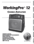
IMPEDANCE GUIDELINES - Use the impedance
ratings on your amplifier and speakers to determine if
a particular combination of speakers is appropriate for
your amplifier. NOTE: All SWR® bass speaker
enclosures, as well as most others, are wired in
parallel (NOT in series), therefore, these
Impedance Guidelines apply only to parallel
speaker connections. The illustration shows
the total impedance loads of various
combinations of speakers linked together.
Generally, you will want to connect your
amplifier to speakers with a total impedance
load equal to the minimum impedance rating
of your amplifier (4–ohms for your
WorkingPro™ amplifier).
Operating below
the minimum impedance rating can easily
overheat the amplifier and cause damage.
Operating above the minimum impedance
rating will reduce the amplifier’s maximum
power output.
✧
Notice that different combinations of speakers can
equal the same total impedance load. If their
impedances are the same, each speaker will receive
equal power from your amplifier. However, if their
impedances are not all the same, speakers with the
lowest impedances will receive most of the
power. For example, if you connect an 8–ohm
speaker and a 16–ohm speaker to your
amplifier, the 8–ohm speaker will receive most
of the power. Take this into consideration when
calculating power handling capacities and
when positioning your bass speaker
enclosures.
For an in-depth discussion of impedance
and power rating issues, go to the SWR®
Website at www.swrsound.com, click on
“Press,” then click on “Articles,” then click
on “Plug and Play: Setup Tips for Amps and
Speakers”—an article by SWR ® founder
Steve Rabe that ran in the August ’92 issue of
Bass Player Magazine.
s w r s o u n d . c o m
✧
R e a r P a n e l —continued
8
-- -- -
---
--
-----
R. HEADPHONES - Plug in your stereo or mono
headphones here. Use MASTER Volume to control
your headphone listening level. Use MUTE {C} to
disable speaker audio output. NOTE: While any
headphones will work, 75–ohms is optimum.
S. EFFECTS SEND / RETURN - Multi-purpose jacks:
EFFECTS SEND provides a preamp output signal that
includes onboard tone shaping. Output level is
controlled by GAIN {D}. EFFECTS RECEIVE provides
a power amp input that can be blended in any ratio
with the onboard preamp signal using EFX BLEND {J}.
The Effects Loop circuit is on a “side chain” of the
main circuit (as in studio recording consoles) to
provide the full sound of your instrument AND the
diversity of your effects units. This circuit also reduces
noise generated by effects units because it is located
after the gain stages in the preamp signal path.
Use only standard 1/4" mono phone plugs
with these jacks. Use a stereo–to–mono adapter if
your source has a stereo plug.
1. Effects Loop - Connect EFFECTS SEND to your
effects device input, then connect the effects
device output to EFFECTS RETURN. NOTE: Set
the wet/dry control on external effects units to the
fully WET position to prevent phasing problems.
Set the input level on external effects as close to
0dB as possible.
2. Multiple Amps - Connect the primary unit’s
EFFECTS SEND to the auxiliary unit’s EFFECTS
RETURN. The primary unit is used to control all
auxiliary units except their MASTER Volumes. Set
EFX BLEND on all auxiliary units fully to WET.
3. Recording or Reinforcement - Connect
EFFECTS SEND to the sound equipment input.
4. Accompaniment - Connect a CD player or drum
machine to EFFECTS RETURN. Control the input
level at its source and by using the EFX BLEND
control {J}.
U. UNBALANCED LINE OUT - Provides unbalanced
preamp output for an auxiliary amplifier or sound
equipment that includes the effects loop signal.
Output level is controlled by GAIN {D}.
V.
TUNER OUT - Plug in your bass guitar tuner here to
enable inline tuning. Use MUTE {C} to disable audio
output while tuning.
W. BALANCED (XLR) OUTPUT - A true electronically
balanced output, suitable for studio and “front-ofhouse” (live) mixing consoles. The function of each of
the three BALANCED OUTPUT switches are
described below. Wiring for the XLR jack at the
BALANCED OUTPUT is (American Standard):
Pin
Wiring
1
Ground
2
Positive
3
Negative
DIRECT / LINE - Connects the BALANCED OUTPUT
to a point in the signal path either before (DIRECT) or
after (LINE) the onboard tone shaping circuits.
DIRECT (pre-EQ)
GROUND / LIFT - Disconnects the BALANCED
OUTPUT ground connection (pin-1) which may reduce
hum noise due a ground loop (non-standard XLR
wiring somewhere in the signal path). Normally leave
this switch out.
GROUNDED (normal)
0dB / –10dB - Reduces the BALANCED OUTPUT by
–10dB.
–10dB (padded)
FOOTSWITCH - Plug in the included footswitch here.
Use the footswitch to remotely switch MUTE and the
BASS INTENSIFIER.
✧
GROUND LIFTED
Lifting the ground connection will not solve hum noise
due to bad cables, poor connections, miswired A/C
outlets, nearby fluorescent lighting (especially with
single-coil pickups) or a cell phone close to your bass.
0dB (normal)
T.
LINE (post-EQ)
s w r s o u n d . c o m
✧
Rack Mounting
To preserve the beauty and reliability of your amplifier, we
recommend that you install your amplifier in a rack case.
The WorkingPro™ is completely ready to be rack mounted
and needs no additional parts or accessories other than
the rack screws and the case itself.
The WorkingPro™ takes up two full rack spaces (3 1/2").
If the rack in which you mount your WorkingPro™ requires
that the rubber feet on the bottom of the chassis be
removed, please remember to keep the screws handy in
case you wish to reattach the rubber feet at a later date.
The WorkingPro™ should be mounted as close to the
bottom of the rack case as possible. If you must mount
the WorkingPro™ in an area of the rack other than the
bottom space, a piece of wood or similar solid material
should be installed between the bottom of the rack case
and the bottom of the amplifier to prevent flexing of the
amplifier's chassis. Severe or constant flexing of the
chassis can damage the amplifier and is not covered
under the warranty.
Please do not forget about your amp after it has been
installed in a rack case. Continuous transportation and
vibration can cause screws to become loose, both on the
WorkingPro™ and with your rack case rails. We
recommend that at least once a month you remove the
WorkingPro™ from the case and tighten all outside screws
and wipe off the outside of the chassis with a damp cloth.
Then check all the connections in your rack case and
reinstall the unit.
Specifications
MODEL:
WorkingPro™ 400
WorkingPro™ 700
PART NUMBERS:
4450200010 (120V, 60Hz) USA
4450203010 (240V, 50Hz) AUS
4450204010 (230V, 50Hz) UK
4450206010 (230V, 50Hz) EUR
4450207010 (100V, 50Hz) JPN
4450000010 (120V, 60Hz) USA
4450003010 (240V, 50Hz) AUS
4450004010 (230V, 50Hz) UK
4450006010 (230V, 50Hz) EUR
4450007010 (100V, 50Hz) JPN
POWER REQUIREMENT:
840 W
1440 W
POWER AMP
4Ω
700mV RMS, 1kHz
400W RMS into 4Ω @ < 0.1% THD, 1kHz
250W RMS into 8Ω @ < 0.1% THD, 1kHz
4Ω
1V RMS, 1kHz
700W RMS into 4Ω @ < 0.1% THD, 1kHz
440W RMS into 8Ω @ < 0.1% THD, 1kHz
3.9MΩ
15mV
3.9MΩ
20mV
±15dB @ 100Hz
±15dB @ 2kHz
±15dB @ MID FREQ frequency
±15dB below CUTOFF freq
±15dB @ 5kHz
±15dB @ 100Hz
±15dB @ 2kHz
±15dB @ MID FREQ frequency
±15dB below CUTOFF freq
±15dB @ 5kHz
2kΩ
27kΩ
2kΩ
27kΩ
1kΩ
1kΩ
1.5kΩ
1.5kΩ
2-button, Mute, Bass Intensifier (P/N 065436)
2-button, Mute, Bass Intensifier (P/N 065436)
T8A, 250V
T4A, 250V
T15A, 250V
T8A, 250V
3.5 in (8.9 cm)
19 in (48.3 cm)
13.5 in (34.3 cm)
3.5 in (8.9 cm)
19 in (48.3 cm)
13.5 in (34.3 cm)
25 lb (11.25 kg)
25 lb (11.25 kg)
PRE AMP
MINIMUM IMPEDANCE:
SENSITIVITY:
POWER OUTPUT:
INPUT IMPEDANCE:
SENSITIVITY AT FULL POWER:
TONE CONTROLS
BASS:
TREBLE:
MIDRANGE SEMI-PARAMETRIC EQ:
BASS INTENSIFIER:
TRANSPARENCY:
EFFECTS LOOP
SEND IMPEDANCE:
RETURN IMPEDANCE:
UNBALANCED LINE OUT SEND IMPEDANCE:
BALANCED LINE OUT
SEND IMPEDANCE:
FOOTSWITCH (INCLUDED):
LINE FUSE
DIMENSIONS
110V-120V MODELS:
230V-240V MODELS:
HEIGHT:
WIDTH:
DEPTH:
WEIGHT:
Product specifications are subject to change without notice.
✧
9
s w r s o u n d . c o m
✧
SWR ®
Corona, California USA
SWR® and WorkingPro™ are trademarks owned by Fender Musical Instruments Corporation.
Other trademarks are property of their respective owners. © 2005 FMIC. All rights reserved.
WorkingPro™ Series Bass Amplifiers • swrsound.com • 01/05