1
SUPER
A+ SERVER
AS-1041A-T2F
USER’S MANUAL
Revision 1.0b
®
The information in this User’s Manual has been carefully reviewed and is believed to be accurate.
The vendor assumes no responsibility for any inaccuracies that may be contained in this document,
makes no commitment to update or to keep current the information in this manual, or to notify any
person or organization of the updates. Please Note: For the most up-to-date version of this
manual, please see our web site at www.supermicro.com.
Super Micro Computer, Inc. ("Supermicro") reserves the right to make changes to the product
described in this manual at any time and without notice. This product, including software and documentation, is the property of Supermicro and/or its licensors, and is supplied only under a license.
Any use or reproduction of this product is not allowed, except as expressly permitted by the terms
of said license.
IN NO EVENT WILL SUPERMICRO BE LIABLE FOR DIRECT, INDIRECT, SPECIAL, INCIDENTAL,
SPECULATIVE OR CONSEQUENTIAL DAMAGES ARISING FROM THE USE OR INABILITY TO
USE THIS PRODUCT OR DOCUMENTATION, EVEN IF ADVISED OF THE POSSIBILITY OF
SUCH DAMAGES. IN PARTICULAR, SUPERMICRO SHALL NOT HAVE LIABILITY FOR ANY
HARDWARE, SOFTWARE, OR DATA STORED OR USED WITH THE PRODUCT, INCLUDING THE
COSTS OF REPAIRING, REPLACING, INTEGRATING, INSTALLING OR RECOVERING SUCH
HARDWARE, SOFTWARE, OR DATA.
Any disputes arising between manufacturer and customer shall be governed by the laws of Santa
Clara County in the State of California, USA. The State of California, County of Santa Clara shall
be the exclusive venue for the resolution of any such disputes. Super Micro's total liability for all
claims will not exceed the price paid for the hardware product.
FCC Statement: This equipment has been tested and found to comply with the limits for a Class A
digital device pursuant to Part 15 of the FCC Rules. These limits are designed to provide reasonable
protection against harmful interference when the equipment is operated in a commercial environment. This equipment generates, uses, and can radiate radio frequency energy and, if not installed
and used in accordance with the manufacturer’s instruction manual, may cause harmful interference
with radio communications. Operation of this equipment in a residential area is likely to cause harmful
interference, in which case you will be required to correct the interference at your own expense.
California Best Management Practices Regulations for Perchlorate Materials: This Perchlorate warning applies only to products containing CR (Manganese Dioxide) Lithium coin cells. “Perchlorate
Material-special handling may apply. See www.dtsc.ca.gov/hazardouswaste/perchlorate”
WARNING: Handling of lead solder materials used in this
product may expose you to lead, a chemical known to the
State of California to cause birth defects and other reproductive harm.
Manual Revision 1.0b
Release Date: December 14, 2010
Unless you request and receive written permission from Super Micro Computer, Inc., you may not
copy any part of this document.
Information in this document is subject to change without notice. Other products and companies
referred to herein are trademarks or registered trademarks of their respective companies or mark
holders.
Copyright © 2010 by Super Micro Computer, Inc.
All rights reserved.
Printed in the United States of America
Preface
Preface
About This Manual
This manual is written for professional system integrators and PC technicians. It
provides information for the installation and use of the A+ SERVER AS-1041A-T2F
Installation and maintenance should be performed by experienced technicians
only.
The A+ SERVER A+ SERVER AS-1041A-T2F is a 1U rackmount server based on
the SC818TQ+-1000 server chassis and the Super H8QIi+-F serverboards.
Manual Organization
Chapter 1: Introduction
The first chapter provides a checklist of the main components included with the
server system and describes the main features of the Super H8QIi+-F serverboard
and the SC818TQ+-1000 chassis.
Chapter 2: Server Installation
This chapter describes the steps necessary to install the A+ SERVER AS-1041AT2F into a rack and check out the server configuration prior to powering up the
system. If your server was ordered without the processor and memory components,
this chapter will refer you to the appropriate sections of the manual for their installation.
Chapter 3: System Interface
Refer to this chapter for details on the system interface, which includes the functions
and information provided by the control panel on the chassis as well as other LEDs
located throughout the system.
Chapter 4: System Safety
You should thoroughly familiarize yourself with this chapter for a general overview
of safety precautions that should be followed when installing and servicing the A+
SERVER AS-1041A-T2F.
Chapter 5: Advanced Serverboard Setup
Chapter 5 provides detailed information on the H8QIi+-F serverboard, including the
locations and functions of connectors, headers and jumpers. Refer to this chapter
when adding or removing processors or main memory and when reconfiguring the
serverboard.
iii
A+ SERVER AS-1041A-T2F User's Manual
Chapter 6: Advanced Chassis Setup
Refer to Chapter 6 for detailed information on the SC818TQ+-1000 1U rackmount
server chassis. You should follow the procedures given in this chapter when installing, removing or reconfiguring SATA or peripheral drives and when replacing system
power supply units and cooling fans.
Chapter 7: BIOS
The BIOS chapter includes an introduction to BIOS and provides detailed information on running the CMOS Setup Utility.
Appendix A: BIOS Error Beep Codes
Appendix B: Installing Windows
Appendix C: System Specifications
iv
Preface
Notes
v
A+ SERVER AS-1041A-T2F User's Manual
Table of Contents
Chapter 1 Introduction
1-1
Overview ......................................................................................................... 1-1
1-2
Serverboard Features ..................................................................................... 1-2
Processors ...................................................................................................... 1-2
Memory ........................................................................................................... 1-2
HyperTransport Technology ............................................................................ 1-2
Serial ATA ........................................................................................................ 1-2
PCI Expansion Slots ....................................................................................... 1-3
Ethernet Ports ................................................................................................. 1-3
Onboard Controllers/Ports .............................................................................. 1-3
Graphics Controller ......................................................................................... 1-3
Other Features ................................................................................................ 1-3
1-3
Server Chassis Features ................................................................................ 1-5
System Power ................................................................................................. 1-5
SATA Subsystem ............................................................................................. 1-5
Front Control Panel ......................................................................................... 1-5
Cooling System ............................................................................................... 1-5
1-4
Contacting Supermicro .................................................................................... 1-6
Chapter 2 Server Installation
2-1
Overview ......................................................................................................... 2-1
2-2
Unpacking the System .................................................................................... 2-1
2-3
Preparing for Setup ......................................................................................... 2-1
Choosing a Setup Location ............................................................................. 2-1
Warnings and Precautions! ........................................................................................ 2-2
Rack Precautions ............................................................................................ 2-2
Server Precautions.......................................................................................... 2-2
Rack Mounting Considerations ....................................................................... 2-3
Ambient Operating Temperature ................................................................ 2-3
Reduced Airflow ......................................................................................... 2-3
Mechanical Loading ................................................................................... 2-3
Circuit Overloading ..................................................................................... 2-3
Reliable Ground ......................................................................................... 2-3
2-4
Installing the System into a Rack ................................................................... 2-4
Identifying the Sections of the Rack Rails ...................................................... 2-4
Installing the Inner Rail Extensions ................................................................ 2-5
Assembling the Outer Rails ............................................................................ 2-6
vi
Table of Contents
Installing the Outer Rails onto the Rack ......................................................... 2-7
Installing the Server into a Telco Rack ........................................................... 2-9
2-5
Checking the Serverboard Setup .................................................................. 2-10
2-6
Checking the Drive Bay Setup .......................................................................2-11
Chapter 3 System Interface
3-1
Overview ......................................................................................................... 3-1
3-2
Control Panel Buttons ..................................................................................... 3-1
Reset ............................................................................................................... 3-1
Power .............................................................................................................. 3-1
3-3
Control Panel LEDs ........................................................................................ 3-2
NIC2 ................................................................................................................ 3-2
NIC1 ................................................................................................................ 3-2
HDD................................................................................................................. 3-2
Power .............................................................................................................. 3-2
Overheat/Fan Fail LED ................................................................................... 3-2
3-4
SATA Drive Carrier LEDs ................................................................................ 3-3
Chapter 4 System Safety
4-1
Electrical Safety Precautions .......................................................................... 4-1
4-2
General Safety Precautions ............................................................................ 4-2
4-3
ESD Precautions ............................................................................................. 4-3
4-4
Operating Precautions .................................................................................... 4-4
Chapter 5 Advanced Serverboard Setup
5-1
Handling the Serverboard ............................................................................... 5-1
5-2
I/O Ports .......................................................................................................... 5-2
Precautions ..................................................................................................... 5-1
Front Control Panel ......................................................................................... 5-2
Unpacking ....................................................................................................... 5-2
5-3
Processor and Heatsink Installation................................................................ 5-3
Installing a Passive Heatsink .......................................................................... 5-5
Removing the Heatsink ................................................................................... 5-5
Removing a Passive Heatsink ................................................................... 5-5
5-4
Installing Memory ............................................................................................ 5-6
5-5
PCI Expansion Cards ...................................................................................... 5-8
5-6
Serverboard Details ...................................................................................... 5-10
5-7
Connector Definitions ....................................................................................5-11
5-8
Jumper Settings ............................................................................................ 5-17
5-9
Onboard Indicators........................................................................................ 5-19
H8QIi+-F Quick Reference.............................................................................. 5-9
vii
A+ SERVER AS-1041A-T2F User's Manual
5-10
IDE and SATA Drive Connections ................................................................. 5-20
5-11
Enabling SATA RAID ..................................................................................... 5-21
Serial ATA (SATA).......................................................................................... 5-21
Installing the OS/SATA Driver ....................................................................... 5-21
Building a Driver Diskette ......................................................................... 5-21
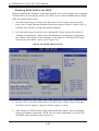
Enabling SATA RAID in the BIOS ............................................................ 5-22
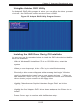
Using the Adaptec RAID Utility ..................................................................... 5-23
Installing the RAID Driver During OS Installation ......................................... 5-23
2-12
Installing Drivers............................................................................................ 5-24
5-13
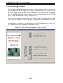
Configuring Supero Doctor III ....................................................................... 5-25
Chapter 6 Advanced Chassis Setup
6-1
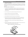
Static-Sensitive Devices .................................................................................. 6-1
Precautions ..................................................................................................... 6-1
6-2
Control Panel .................................................................................................. 6-2
6-3
System Cooling ............................................................................................... 6-2
6-4
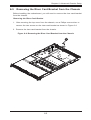
Removing the Top Cover from the Chassis .................................................... 6-4
6-5
Removing the Riser Card Bracket from the Chassis ...................................... 6-5
6-6
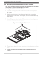
Installing the Motherboard into the Chassis ................................................... 6-6
6-7
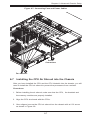
Installing the CPU Air Shroud into the Chassis .............................................. 6-7
6-9
Drive Bay Installation/Removal ....................................................................... 6-9
System Fan Failure ......................................................................................... 6-3
Accessing the Drive Bays ............................................................................... 6-9
Hard Drive Installation ..................................................................................... 6-9
Peripheral Drive Installation .......................................................................... 6-12
6-10
Checking the Air Flow ................................................................................... 6-13
6-11
Power Supply ................................................................................................ 6-13
Power Supply Failure .................................................................................... 6-13
Chapter 7 BIOS
7-1
Introduction...................................................................................................... 7-1
Starting BIOS Setup Utility .............................................................................. 7-1
How To Change the Configuration Data ......................................................... 7-1
Starting the Setup Utility ................................................................................. 7-2
7-2
Main Setup ...................................................................................................... 7-2
4-3
Advanced Settings Menu ................................................................................ 7-3
4-5
Boot Settings Menu ....................................................................................... 7-21
4-6
Security Menu ............................................................................................... 7-22
4-8
Exit Menu ...................................................................................................... 7-23
viii
Table of Contents
Appendix A BIOS Error Beep Codes
Appendix B Installing Windows
B-1
Installing Windows to a RAID System ............................................................ B-1
B-2
Installing Windows to a Non-RAID System .................................................... B-2
Appendix C System Specifications
SATA Drive Bays .............................................................................................C-1
PCI Expansion ................................................................................................C-1
ix
A+ SERVER AS-1041A-T2F User's Manual
Notes
x
Chapter 1: Introduction
Chapter 1
Introduction
1-1
Overview
The A+ SERVER AS-1041A-T2F is a 1U server comprised of the SC818TQ+-1000
chassis and one H8QIi+-F serverboard. Please refer to our web site for information on operating systems that have been certified for use with the server (www.
supermicro.com).
In addition to the serverboard and chassis, various hardware components may have
been included with the system, as listed below.
•
Four (4) passive CPU heatsinks (SNK-P0022+)
•
Six (6) 40x56mm 4-pin PWM cooling fans (FAN-0102L4)
•
One (1) Air shroud for SC818-1000 AMD CPU (CSE-PT0128)
•
•
SATA Accessories:
Three hard drive carriers (CSE-PT39-B0)
One (1) internal 818 SAS HDD backplane (BPN-SAS-818TQ)
One (1) 40-cm 8-pin to 8-pin SGPIO ribbon cable with tube (CBL-0157L)
Three (3) 48-cm SATA round cable sets (CBL-0206L)
DVD-ROM
One (1) Panasonic Black Slim IDE DVD (DVM-PNSC-824B)
One (1) 50-cm 80-wire cable for DVD-ROM (CBL-0139L)
One (1) Mini IDE-to-IDE adapter for slim DVD (CDM-CDSC)
•
ONe (1) PCI Express x16 card (CSE-RR1U-E16)
•
One (1) Third generation guide rail assembly kit (CSE-PT51)
•
One CD containing drivers and utilities
•
Optional:
One (1) Black Slim TEAC Floppy Drive (FPD-TEAC-SB)
One (1) 5-cm FDD power adapter cable (CBL-0210L)
1-1
A+ SERVER AS-1041A-T2F User's Manual
1-2
Serverboard Features
At the heart of the A+ SERVER AS-1041A-T2F is the H8QIi+-F quad Opteron
8300/8400 series (Socket F type) processor serverboard, which is based on a AMD
SR5690 (North Bridge) and a SP5100 (South Bridge) chipset.
Below are the main features of the serverboards.
Processors
The H8QIi+-F supports quad Opteron 8000 series processors in Socket F type
sockets. Please refer to our web site for a complete listing of supported processors
(www.supermicro.com).
Memory
The H8QIi+-F has sixteen DIMM sockets that can support up to 128 GB of DDR2800/667/533 registered ECC SDRAM. See Chapter 5 Section 4 for more details on
installing memory into the system.
HyperTransport Technology
HyperTransport technology is a high-speed, low latency point to point link that was
designed to increase the communication speed by a factor of up to 48x between
integrated circuits. This is done partly by reducing the number of buses in the
chipset to reduce bottlenecks and by enabling a more efficient use of memory
in multi-processor systems. The end result is a significant increase in bandwidth
within the chipset.
The H8QIi+-F serverboard contains two HTx Connectors for plug-in cards that allow
a direct connection between the installed cards and the processor, and to have direct
DMA access to the system RAM at 16-bits and 800 Mhz speed
Serial ATA
The South Bridge (SP5100) of the chipset includes a Serial ATA controller for six
Gb/s SATA drives. The hot-swappable SATA drives are connected to a backplane
that provides power, bus termination and configuration settings. RAID 0, 1, and 10
are supported. Refer to the support area of our web site for procedures on setting
up RAID on your system.
1-2
Chapter 1: Introduction
PCI Expansion Slots
The H8QIi+-F board has one (1) PCI-Express x16 slot and one (1) HTx Connector.
Four riser cards have been provided with the server to support the installation of
low-profile add-on cards.
Ethernet Ports
An Intel® network controller is integrated into each of the serverboards to support
two Gigabit LAN ports (100/1000Base-T/1000BaseTX, RJ45 output).
Onboard Controllers/Ports
Onboard I/O backpanel ports on each serverboard includes two Fast UART 16550
compatible serial ports (one header and one port), a VGA port, six USB (Universal
Serial Bus 2.0) ports (2x rear, 2x header, 2x type A), a dedicated IPMI LAN port,
two Gigabit LAN (NIC) ports and one UDMA IDE 133/100 connector.
Graphics Controller
The H8QIi+-F features an integrated Matrox G200eW graphics chip, which includes
16 MB of DDR2 memory.
Other Features
Other onboard features that promote system health include voltage monitors, autoswitching voltage regulators, chassis and CPU overheat sensors, main switch override mechanism, Wake-on-LAN, Wake-on-Ring, chassis intrusion detection, virus
protection and BIOS rescue.
1-3
A+ SERVER AS-1041A-T2F User's Manual
I/O CONN.
HT Link
VRM
HT Link
DDR2-533/667
1207-SOCKET #4
4x DIMM
DDR2-533/667
1207-SOCKET #3
16/16-1GHz
VRM
4x DIMM
HT Link
16/16-1GHz
HT Link
16/16-1GHz
VRM
HT Link
DDR2-533/667
4x DIMM
16/16-1GHz
HT Link
16/16-1GHz
VRM
I/O_CONN.
HTX
1207-SOCKET #2
16/16-1GHz
DDR2-533/667
1207-SOCKET #1
4x DIMM
HT Link
16/16-1GHz
PCIE (x4)
Intel
82576
AMD
SR5690
PCIE (X16)
VGA
Winbond
WPCM450
AMD
SP5100
SLOT#6
PCIE_(X16)
SATA
6x PORTS
SATA_CONN
UDMA/133
IDE
PRI/SEC
USB
USB PORT(0-5)
LPC BUS
H/W_MONITOR
W83795
LPC I/O
W83627HF
FWH
KB.
Fan Control
MS.
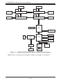
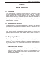
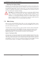
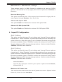
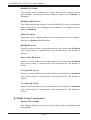
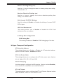
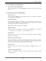
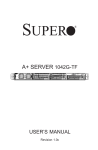
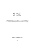
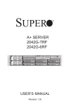
Figure 1-1. AMD SR5690/SP5100 Chipset: System Block Diagram
Note: This is a general block diagram. Please see Chapter 5 for details.
1-4
Chapter 1: Introduction
1-3
Server Chassis Features
System Power
The SC818TQ+-1000 features a 1000W high-efficiency power supply. The AC power
cord should be removed from the system before servicing or replacing the power
supply. See Chapter 6 for details.
SATA Subsystem
The SC818TQ+-1000 chassis includes three 3.5" drive bays, which may be used
to house hot-swappable SATA drives. RAID 0, 1 and 10 are supported.
Front Control Panel
The control panel provides a system monitoring and control interface. LEDs indicate
system power, HDD activity, network activity, system overheat and power supply
failure. A main power button and a system reset button are also included.
Cooling System
The SC818TQ+-1000 has an innovative cooling design that includes six 40x56mm
counter-rotating PWM (Pulse Width Modulated) fans located in the middle section
of the chassis. The power supply module also includes a cooling fan. All chassis
and power supply fans operate continuously. An air shroud channels the airflow
from the system fans to efficiently cool the processors and memory. See note on
the following page regarding fan control.
1-5
A+ SERVER AS-1041A-T2F User's Manual
1-4
Contacting Supermicro
Headquarters
Address:
Super Micro Computer, Inc.
980 Rock Ave.
San Jose, CA 95131 U.S.A.
Tel:
+1 (408) 503-8000
Fax:
+1 (408) 503-8008
Email:
[email protected] (General Information)
[email protected] (Technical Support)
Web Site:
www.supermicro.com
Europe
Address:
Super Micro Computer B.V.
Het Sterrenbeeld 28, 5215 ML
's-Hertogenbosch, The Netherlands
Tel:
+31 (0) 73-6400390
Fax:
+31 (0) 73-6416525
Email:
[email protected] (General Information)
[email protected] (Technical Support)
[email protected] (Customer Support)
Asia-Pacific
Address:
Super Micro Computer, Inc.
4F, No. 232-1, Liancheng Rd.
Chung-Ho 235, Taipei County
Taiwan, R.O.C.
Tel:
+886-(2) 8226-3990
Fax:
+886-(2) 8226-3991
Web Site:
www.supermicro.com.tw
Technical Support:
Email:
[email protected]
Tel:
886-2-8228-1366, ext.132 or 139
1-6
Chapter 2: Server Installation
Chapter 2
Server Installation
2-1
Overview
This chapter provides a quick setup checklist to get your A+ SERVER up and
running. Following these steps in the order given should enable you to have the
system operational within a minimum amount of time. This quick setup assumes
that your system has come to you with the processors and memory preinstalled. If
your system is not already fully integrated with a serverboard, processors, system
memory etc., please turn to the chapter or section noted in each step for details on
installing specific components.
2-2
Unpacking the System
You should inspect the box the system was shipped in and note if it was damaged
in any way. If the server itself shows damage you should file a damage claim with
the carrier who delivered it.
Decide on a suitable location for the rack unit that will hold the server. It should
be situated in a clean, dust-free area that is well ventilated. Avoid areas where
heat, electrical noise and electromagnetic fields are generated. You will also need
it placed near a grounded power outlet. Read the Rack and Server Precautions in
the next section.
2-3
Preparing for Setup
The box the server was shipped in should include two sets of rail assemblies, two
rail mounting brackets and the mounting screws you will need to install the system
into the rack. Follow the steps in the order given to complete the installation process
in a minimum amount of time. Please read this section in its entirety before you
begin the installation procedure outlined in the sections that follow.
Choosing a Setup Location
•
Leave enough clearance in front of the rack to enable you to open the front door
completely (~25 inches) and approximately 30 inches of clearance in the back
of the rack to allow for sufficient airflow and ease in servicing.This product is for
installation only in a Restricted Access Location (dedicated equipment rooms,
service closets and the like).
2-1
A+ SERVER AS-1041A-T2F User's Manual
•
This product is not suitable for use with visual display work place devices
acccording to §2 of the the German Ordinance for Work with Visual Display
Units.
!
Warnings and Precautions!
!
Rack Precautions
•
•
•
•
•
Ensure that the leveling jacks on the bottom of the rack are fully extended to
the floor with the full weight of the rack resting on them.
In single rack installation, stabilizers should be attached to the rack. In multiple
rack installations, the racks should be coupled together.
Always make sure the rack is stable before extending a component from the
rack.
You should extend only one component at a time - extending two or more simultaneously may cause the rack to become unstable.
Rack-mounted equipment should not be used as a shelf or work space.
Server Precautions
•
•
•
•
•
Review the electrical and general safety precautions in Chapter 4.
Determine the placement of each component in the rack before you install the
rails.
Install the heaviest server components on the bottom of the rack first, and then
work up.
Use a regulating uninterruptible power supply (UPS) to protect the server from
power surges, voltage spikes and to keep your system operating in case of a
power failure.
Allow the hot plug SATA drives and power supply modules to cool before touching them.
2-2
Chapter 2: Server Installation
•
Always keep the rack's front door and all panels and components on the servers
closed when not servicing to maintain proper cooling.
Rack Mounting Considerations
Ambient Operating Temperature
If installed in a closed or multi-unit rack assembly, the ambient operating temperature of the rack environment may be greater than the ambient temperature of the
room. Therefore, consideration should be given to installing the equipment in an
environment compatible with the manufacturer’s maximum rated ambient temperature (Tmra).
Reduced Airflow
Equipment should be mounted into a rack so that the amount of airflow required
for safe operation is not compromised.
Mechanical Loading
Equipment should be mounted into a rack so that a hazardous condition does not
arise due to uneven mechanical loading.
Circuit Overloading
Consideration should be given to the connection of the equipment to the power
supply circuitry and the effect that any possible overloading of circuits might have
on overcurrent protection and power supply wiring. Appropriate consideration of
equipment nameplate ratings should be used when addressing this concern.
Reliable Ground
A reliable ground must be maintained at all times. To ensure this, the rack itself
should be grounded. Particular attention should be given to power supply connections other than the direct connections to the branch circuit (i.e. the use of power
strips, etc.).
2-3
A+ SERVER AS-1041A-T2F User's Manual
2-4
Installing the System into a Rack
This section provides information on installing the SC818G chassis into a rack unit
with the rails provided. There are a variety of rack units on the market, which may
mean that the assembly procedure will differ slightly. You should also refer to the
installation instructions that came with the rack unit you are using.
Note: This rail will fit a rack between 26" and 33.5" deep.
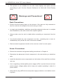
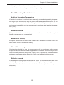
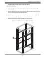
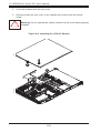
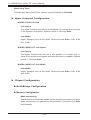
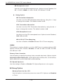
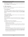
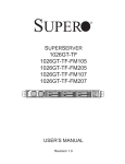
Identifying the Sections of the Rack Rails
The chassis package includes two rack rail assemblies in the rack mounting kit.
Each assembly consists of two sections: an inner fixed chassis rail that secures
directly to the server chassis and an outer fixed rack rail that secures directly to
the rack itself.
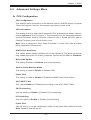
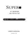
Figure 2-1. Identifying the Sections of the Rack Rails
Inner Rail (preattached
to the chassis)
Inner Rail
Extension:
attach to the
chassis
Outer Rails:
slide together, then
attach to the front
and rear brackets
Front and Rear
Brackets: attach to
the rack
2-4
Chapter 2: Server Installation
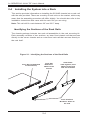
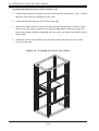
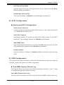
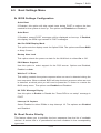
Installing the Inner Rail Extensions
The SC818G chassis includes a set of inner rack rails in two sections: inner rails (A)
and inner rail extensions (B). The inner rails are preattached and do not interfere
with normal use of the chassis if you decide not to install to a server rack. Attaching
the inner rail extensions to to the inner rails stabilizes the chassis within the rack.
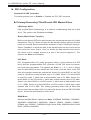
Installing the Inner Rail Extensions
1. Place the inner rail extensions (B) over the preattached inner rails (A) which
are attached to the side of the chassis. Align the hooks of the inner rail with
the rail extension holes. Make sure the extension faces "outward" just like the
inner rail.
2. Slide the extension toward the front of the chassis.
3. Secure the chassis with screws as illustrated.
4. Repeat steps 1-3 for the other inner rail extension.
Figure 2-2. Installing the Inner Rails
1
12
13
2-5
A+ SERVER AS-1041A-T2F User's Manual
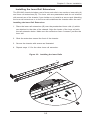
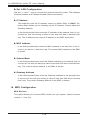
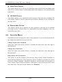
Assembling the Outer Rails
Each outer rail is in two sections that must be assembled before mounting on to
the rack.
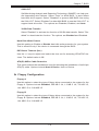
Assembling the Outer Rails
1. Identify the left and right outer rails by examining the ends, which bend
outward.
2. Slide the front section of the outer rail (A), into the rear section of the outer
rail (B).
Figure 2-3. Assembling the Outer Rails
Secure to the
rear of the rack
Slide outer rails
together
B
1
Secure to the
front of the rack
1A
Assembling the sections of
the outer rail
Outer rail assembled
2-6
Chapter 2: Server Installation
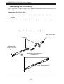
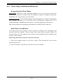
Installing the Outer Rails onto the Rack
Outer Rail Installation
1. Adjust the outer rails to the proper length so that the outer rail fits snugly
within the rack.
2. Align the holes on the front of the outer rail, with the holes on the front of the
rack (C) and secure with the screws provided.
3. Align the holes on the rear of the outer rail to the holes on the rack (D) and
secure with the screws provided.
4. Repeat the procedure with the second outer rail assembly.
Figure 2-4. Installing the Outer Rails to the Rack
D
1
C
1
2-7
A+ SERVER AS-1041A-T2F User's Manual
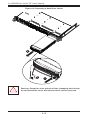
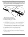
Installing the Chassis into a Rack (Figure 2-5)
1. Confirm that chassis includes the inner rails and rail extensions . Also, confirm
that the outer rails are installed on the rack.
2. Line chassis rails with the front of the rack rails.
3. Slide the chassis rails into the rack rails, keeping the pressure even on both
sides (you may have to depress the locking tabs when inserting). When the
server has been pushed completely into the rack, you should hear the locking
tabs "click".
4. (Optional) Insert and tightening the thumbscrews that hold the front of the
server to the rack.
Figure 2-5. Installing the Server into a Rack
2-8
Chapter 2: Server Installation
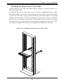
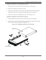
Installing the Server into a Telco Rack
Optional brackets (p/n MCP-290-00016-0N) are needed to install the server to a
telco (open type) rack.
To install the server into a Telco type rack, use the two L-shaped brackets on either
side of the chassis (four total). First, determine how far follow the server will extend
out the front of the rack. Larger chassis should be positioned to balance the weight
between front and back. If a bezel is included on your server, remove it. Then attach the two front brackets to each side of the chassis, then the two rear brackets
positioned with just enough space to accommodate the width of the telco rack. Finish
by sliding the chassis into the rack and tightening the brackets to the rack.
Figure 2-6. Installing the Server into a Telco Rack
2-9
A+ SERVER AS-1041A-T2F User's Manual
2-5
Checking the Serverboard Setup
After you install the server in the rack, you will need to open the unit to make sure
the serverboard is properly installed and all the connections have been made.
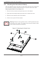
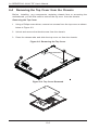
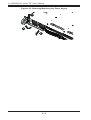
Removing the Chassis Cover (Figure 2-7)
1. Remove the three screws securing the top cover to the chassis.
2. Press both of the release tabs at the same time to release the cover
3. Slide the cover toward the rear of the chassis.
4. Lift the cover up and off of the chassis.
!
Warning: Except for short periods of time, do NOT operate the server
without the cover in place. The chassis cover must be in place to allow
proper airflow and prevent overheating.
Figure 2-7: Removing the Chassis Cover
14
1
1
13
1
12
12
2-10
Chapter 2: Server Installation
Checking the Components
1. You may have processors already installed to the serverboard. Each
processor needs its own heatsink. See Chapter 5 for instructions on
processor and heatsink installation.
2. Your server system may have come with system memory already installed.
Make sure all DIMMs are fully seated in their slots. For details on adding
system memory, refer to Chapter 5.
3. If desired, you can install add-on cards to the system. See Chapter 5 for
details on installing PCI add-on cards.
4. Make sure all power and data cables are properly connected and not blocking
the chassis airflow. See Chapter 5 for details on cable connections. Also,
check the air seals for damage. The air seals are located under the blower
fan and beneath the frame cross section that separates the drive bay area
from the serverboard area of the chassis.
2-6
Checking the Drive Bay Setup
Next, you should check to make sure the hard drives have been properly installed
and all connections have been made.
Checking the Drives
1. You can add or remove hard drives from the drive carriers without having to
remove the top chassis cover.
2. If you need to remove or install hard drives, please refer to Chapter 6.
Checking the Airflow
1. Airflow is provided by 4-cm counter-rotating fans. The system component
layout was carefully designed to direct sufficient cooling airflow to the
components that generate the most heat.
2-11
A+ SERVER AS-1041A-T2F User's Manual
2. Note that all power and data cables have been routed in such a way that they
do not block the airflow generated by the fans.
Providing Power
1. The last thing you must do is to provide input power to the system. Plug the
power cord from the power supply unit into a high-quality power strip that
offers protection from electrical noise and power surges. It is recommended
that you use an uninterruptible power supply (UPS).
2. Finish by depressing the power button on the chassis control panel.
2-12
Chapter 3: System Interface
Chapter 3
System Interface
3-1
Overview
There are several LEDs on the control panel as well as others on the drive carriers to keep you constantly informed of the overall status of the system as well
as the activity and health of specific components. There are also two buttons on
the chassis control panel and an on/off switch on the power supply. This chapter
explains the meanings of all LED indicators and the appropriate response you may
need to take.
3-2
Control Panel Buttons
There are two push-buttons located on the front of the chassis: a reset button and
a power on/off button.
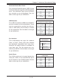
Reset
Use the reset button to reboot the system.
Power
The main power button is used to apply or remove power from the power supply
to the server system. Turning off system power with this button removes the main
power but keeps standby power supplied to the system.
3-1
A+ SERVER 6016T-GTF/GIBXF/GIQXF User's Manual
3-3
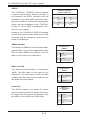
Control Panel LEDs
The control panel located on the front of the SC818TQ chassis has five LEDs. These
LEDs provide you with critical information related to different parts of the system.
This section explains what each LED indicates when illuminated and any corrective
action you may need to take.
2
NIC2
Indicates network activity on LAN2 when flashing .
1
NIC1
Indicates network activity on LAN1 when flashing .
HDD
This light indicates SATA and/or DVD-ROM drive activity when flashing.
Power
Indicates power is being supplied to the system's power supply units. This LED
should normally be illuminated when the system is operating.
Overheat/Fan Fail LED
This LED indicates chassis overheating or a fan failure in the chassis..
3-2
Chapter 3: System Interface
3-4
•
•
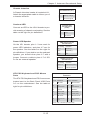
SATA Drive Carrier LEDs
Green: Each Serial ATA drive carrier has a green LED. When illuminated, this
green LED (on the front of the SATA drive carrier) indicates drive activity. A
connection to the SATA backplane enables this LED to blink on and off when
that particular drive is being accessed. Please refer to Chapter 6 for instructions
on replacing failed SATA drives.
Red: The red LED to indicate an SATA drive failure. If one of the SATA drives
fail, you should be notified by your system management software. Please refer
to Chapter 6 for instructions on replacing failed SATA drives.
3-3
A+ SERVER 6016T-GTF/GIBXF/GIQXF User's Manual
Notes
3-4
Chapter 4: System Safety
Chapter 4
System Safety
4-1
Electrical Safety Precautions
!
Basic electrical safety precautions should be followed to protect yourself from harm
and the A+ SERVER AS-4021GA-62R+F from damage:
•
•
•
•
•
Be aware of the locations of the power on/off switch on the chassis as well
as the room's emergency power-off switch, disconnection switch or electrical
outlet. If an electrical accident occurs, you can then quickly remove power from
the system.
Do not work alone when working with high voltage components.
Power should always be disconnected from the system when removing or installing main system components, such as the serverboard, memory modules
and floppy drive. When disconnecting power, you should first power down the
operating system first and then unplug the power cords. The unit has more than
one power supply cord. Disconnect two power supply cords before servicing to
avoid electrical shock.
When working around exposed electrical circuits, another person who is familiar
with the power-off controls should be nearby to switch off the power if necessary.
Use only one hand when working with powered-on electrical equipment. This
is to avoid making a complete circuit, which will cause electrical shock. Use
extreme caution when using metal tools, which can easily damage any electrical
components or circuit boards they come into contact with.
•
•
Do not use mats designed to decrease static electrical discharge as protection
from electrical shock. Instead, use rubber mats that have been specifically
designed as electrical insulators.
The power supply power cords must include a grounding plug and must be
plugged into grounded electrical outlets.
4-1
A+ SERVER AS-1041A-T2F User's Manual
•
•
•
•
4-2
This product may be connected to an IT power system. In all cases, make sure
that the unit is also reliably connected to Earth (ground).
Serverboard Battery: CAUTION - There is a danger of explosion if the onboard
battery is installed upside down, which will reverse its polarites (see Figure
4-1). This battery must be replaced only with the same or an equivalent type
recommended by the manufacturer. Dispose of used batteries according to the
manufacturer's instructions.
DVD-ROM Laser: CAUTION - this server may have come equipped with a
DVD-ROM drive. To prevent direct exposure to the laser beam and hazardous
radiation exposure, do not open the enclosure or use the unit in any unconventional way.
Mainboard replaceable soldered-in fuses: Self-resetting PTC (Positive Temperature Coefficient) fuses on the mainboard must be replaced by trained service
technicians only. The new fuse must be the same or equivalent as the one
replaced. Contact technical support for details and support.
General Safety Precautions
!
Follow these rules to ensure general safety:
•
•
•
•
Keep the area around the AS-4021GA-62R+F clean and free of clutter.
The AS-4021GA-62R+F weighs approximately 72 lbs (32.7 kg) when fully
loaded. When lifting the system, two people at either end should lift slowly with
their feet spread out to distribute the weight. Always keep your back straight
and lift with your legs.
Place the chassis top cover and any system components that have been removed away from the system or on a table so that they won't accidentally be
stepped on.
While working on the system, do not wear loose clothing such as neckties and
unbuttoned shirt sleeves, which can come into contact with electrical circuits or
be pulled into a cooling fan.
4-2
Chapter 4: System Safety
•
•
4-3
Remove any jewelry or metal objects from your body, which are excellent metal
conductors that can create short circuits and harm you if they come into contact
with printed circuit boards or areas where power is present.
After accessing the inside of the system, close the system back up and secure
it to the rack unit with the retention screws after ensuring that all connections
have been made.
ESD Precautions
!
Electrostatic discharge (ESD) is generated by two objects with different electrical
charges coming into contact with each other. An electrical discharge is created to
neutralize this difference, which can damage electronic components and printed
circuit boards. The following measures are generally sufficient to neutralize this
difference before contact is made to protect your equipment from ESD:
•
•
•
•
•
•
•
•
Use a grounded wrist strap designed to prevent static discharge.
Keep all components and printed circuit boards (PCBs) in their antistatic bags
until ready for use.
Touch a grounded metal object before removing the board from the antistatic
bag.
Do not let components or PCBs come into contact with your clothing, which may
retain a charge even if you are wearing a wrist strap.
Handle a board by its edges only; do not touch its components, peripheral chips,
memory modules or contacts.
When handling chips or modules, avoid touching their pins.
Put the serverboard and peripherals back into their antistatic bags when not
in use.
For grounding purposes, make sure your computer chassis provides excellent
conductivity between the power supply, the case, the mounting fasteners and
the serverboard.
4-3
A+ SERVER AS-1041A-T2F User's Manual
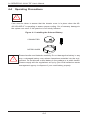
4-4
Operating Precautions
!
Care must be taken to assure that the chassis cover is in place when the AS4021GA-62R+F is operating to assure proper cooling. Out of warranty damage to
the system can occur if this practice is not strictly followed.
Figure 4-1. Installing the Onboard Battery
LITHIUM BATTERY
BATTERY HOLDER
!
Please handle used batteries carefully. Do not damage the battery in any
way; a damaged battery may release hazardous materials into the environment. Do not discard a used battery in the garbage or a public landfill.
Please comply with the regulations set up by your local hazardous waste
management agency to dispose of your used battery properly.
4-4
Chapter 5: Advanced Serverboard Setup
Chapter 5
Advanced Serverboard Setup
This chapter covers the steps required to install the H8QIi+-F serverboard into the
SC818TQ+-1000 chassis, connect the data and power cables and install add-on
cards. All serverboard jumpers and connections are also described. A layout and
quick reference chart are included in this chapter for your reference. Remember to
completely close the chassis when you have finished working with the serverboard
to better cool and protect the system.
5-1
Handling the Serverboard
Electrostatic Discharge (ESD) can damage electronic components. To prevent
damage to any printed circuit boards (PCBs), it is important to handle them very
carefully (see previous chapter). To prevent the H8QIi+-F serverboard from bending, keep one hand under the center of the board to support it when handling. The
following measures are generally sufficient to protect your equipment from electric
static discharge.
Precautions
•
•
Use a grounded wrist strap designed to prevent Electrostatic Discharge
(ESD).
Touch a grounded metal object before removing any board from its antistatic
bag.
•
•
•
•
Handle a board by its edges only; do not touch its components, peripheral chips,
memory modules or gold contacts.
When handling chips or modules, avoid touching their pins.
Put the serverboard, add-on cards and peripherals back into their antistatic
bags when not in use.
For grounding purposes, make sure your computer chassis provides excellent
conductivity between the power supply, the case, the mounting fasteners and
the serverboard.
5-1
A+ SERVER AS-1041A-T2F User's Manual
Unpacking
The serverboard is shipped in antistatic packaging to avoid electrostatic discharge.
When unpacking the board, make sure the person handling it is static protected.
5-2
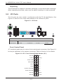
I/O Ports
The I/O ports are color coded in conformance with the PC 99 specification. See
Figure 5-1 below for the colors and locations of the various I/O ports.
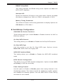
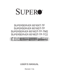
Figure 5-1. I/O Ports
2
8
4
1
3
5
6
7
10
9
Rear I/O Ports
1. Keyboard
3. USB0
5. COM1
7. LAN1
9. IPMI LAN
2. PS/2 Mouse
4. USB1
6. VGA Port
8. LAN2
10. UID
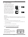
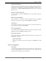
Front Control Panel
JF1 contains header pins for various front control panel connectors. See Figure 2-3
for the pin definitions of the various connectors. Refer to Section 2-6 for details.
Figure 2-3. JF1: Front Control Panel Header (JF1)
20
19
Ground
NMI
x (key)
x (key)
Power LED
Vcc
HDD LED
Vcc
NIC1
Vcc
NIC2
Vcc
OH/Fan Fail LED
Vcc
Power Fail LED
Vcc
Ground
Reset
Ground
Power
2
5-2
1
Chapter 5: Advanced Serverboard Setup
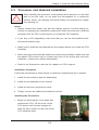
5-3
Processor and Heatsink Installation
!
When handling the processor, avoid placing direct pressure on the label
area of the fan. Also, do not place the serverboard on a conductive
surface, which can damage the BIOS battery and prevent the system
from booting up.
Notes:
Always connect the power cord last and always remove it before adding, removing or changing any hardware components. Make sure that you install the
processor into the CPU socket before you install the CPU heatsink.
•
•
•
•
•
If you buy a CPU separately, make sure that you use an Intel-certified multidirectional heatsink only.
Make sure to install the serverboard into the chassis before you install the CPU
heatsinks.
When receiving a serverboard without a processor pre-installed, make sure that
the plastic CPU socket cap is in place and none of the socket pins are bent;
otherwise, contact your retailer immediately.
Refer to the Supermicro web site for updates on CPU support.
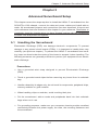
Installation Procedure
Follow the procedures as listed below to install the motherboard into a chassis.
1. Install the processor(s) and the heatsink(s).
2. Install the motherboard in the chassis.
3. Install the memory and add-on cards.
4. Finally, connect the cables and install the drivers.
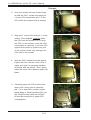
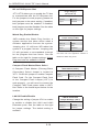
Installing the Processors
1. Begin by removing the cover plate that
protects the CPU. Lift the lever on the
CPU socket until it points straight up.
With the lever raised, lift open the silver
CPU retention plate.
5-3
A+ SERVER AS-1041A-T2F User's Manual
Triangles
2. Use your thumb and your index finger
to hold the CPU. Locate and align pin
1 of the CPU socket with pin 1 of the
CPU. Both are marked with a triangle.
3. Align pin 1 of the CPU with pin 1 of the
socket. Once aligned, carefully place
the CPU into the socket. Do not drop
the CPU on the socket, move the CPU
horizontally or vertically or rub the CPU
against the socket or against any pins
of the socket, which may damage the
CPU and/or the socket.
4. With the CPU inserted into the socket,
inspect the four corners of the CPU to
make sure that it is properly installed
and flush with the socket. Then, gently
lower the silver CPU retention plate into
place.
5. Carefully press the CPU socket lever
down until it locks into its retention
tab. For a dual-CPU system, repeat
these steps to install another CPU into
the CPU#2 socket (and into CPU#2,
#3 and #4 sockets for a quad-CPU
configuration).
5-4
Chapter 5: Advanced Serverboard Setup
Note: in single and dual-CPU configurations, memory must be installed in the DIMM
slots associated with the installed CPU(s). Memory is limited to a maximum of 32
for single CPU and 64 GB for dual CPU configurations.
Installing a Passive Heatsink
To install the SNK-0022+ Passive Heatsink, use the following procedure:
Installing a SNK-0022+ Passive Heatsink
Note: Do not apply any thermal grease to the heatsink - the required amount has
already been applied.
1. Hold the heatsink and place the heatsink on top of the CPU so that the two
mounting holes are aligned with those on the retension mechanism.
2. Make sure the force of the screwdriver torsion is under 6.025 kgf-cm (5.23
lbs-in), and keep screw direction vertical.
3. Screw in two opposite screws until they are just snug (do not fully tighten
them yet).
4. Finish by fully tightening both screws after they are both in snug.
Note: see Chapter 6 for details on installing the air shroud.
Removing the Heatsink
!
Warning: We do not recommend removing the CPU or the heatsink. If
you do need to remove the heatsink, please follow the instructions below
to prevent damage to the CPU or other components.
Removing a Passive Heatsink
1. Unplug the power cord from the power supply.
2. Use your fingertips to gently press on the fastener cap. Then turn it
counterclockwise for a 1/4 (900) turn and then pull the fastener upward to
loosen it.
3. Repeat Step 3 to loosen all fasteners from the mounting holes.
4. With all fasteners loosened, remove the heatsink from the CPU.
5-5
A+ SERVER AS-1041A-T2F User's Manual
5-4
Installing Memory
!
CAUTION! Exercise extreme care when installing or removing
DIMM modules to prevent any possible damage.
Memory Support
Each H8QIi+-F has sixteen 240-pin DIMM slots that can support single or dualchannel, DDR2-800/667/533/400 registered ECC SDRAM (for a total of 128 GB
in the system).
Note: Check the Supermicro web site for recommended DIMMs.
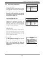
Installing Memory
1. Insert each memory module vertically into its slot, paying attention to the
notch along the bottom of the module to prevent inserting the module
incorrectly (see Figure 2-1).
2. Install to slots CPU1/DIMM1A and CPU1/DIMM1B first, then to CPU1/
DIMM2A and CPU1/DIMM2B, etc. Always install in pairs and in the numerical
order of the DIMM slots. See support information below.
3. Gently press down on the memory module until it snaps into place.
4. With two CPUs installed, repeat step 2 to populate the CPU2 DIMM slots.
Always install pairs of DIMMs to both CPU DIMM slots for more efficient
operation.
Note: 256 MB, 512 MB, 1 GB, 2 GB, 4 GB and 8 GB memory modules are supported. It is highly recommended that you remove the power cord from the system
before installing or changing memory modules. Please refer to our web site for
memory that has been tested on the H8QI6/i(+)(-F) serverboard.
Support
The H8QI6/i(+)(-F) serverboard supports single or dual-channel, DDR2800/667/533/400 registered ECC SDRAM. Only interleaved memory is supported,
so you must populate two DIMM slots at a time (see procedure above).
Populating two adjacent slots at a time with memory modules of the same size and
type will result in interleaved (128-bit) memory, which is faster than non-interleaved
(64-bit) memory. Note: Due to a CPU limitation, fully populating DIMM slots with
DDR2-667 will pull the speed down to 533 MHz. Please see our web site for possible updates to this limitation.
5-6
Chapter 5: Advanced Serverboard Setup
Figure 5-2. Side and Top Views of DDR Installation
Notch
To Install:
Insert module vertically and press
down until it snaps into place. The
release tabs should close - if they do
not you should close them yourself.
Notch
Release
Tab
Note: Notch
should align
with its
receptive point
on the slot
Release
Tab
Note the notch in the slot and on the bottom of the DIMM.
These prevent the DIMM from being installed incorrectly.
To Remove:
Use your thumbs to gently push each
release tab outward to release the
DIMM from the slot.
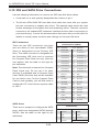
Due to the memory allocation to system devices, the amount of memory that
remains available for operational use will be reduced when 4 GB of RAM is used.
The reduction in memory availability is disproportional. Refer to the table below.
Possible System Memory Allocation & Availability
System Device
Size
Physical Memory Remaining
(Available)
(3 GB Total System Memory)
Physical Memory Remaining
(Available)
(4 GB Total System Memory)
Firmware Hub
flash memory
(System BIOS)
1 MB
3.00
3.99
Local APIC
4 KB
3.00
3.99
Area Reserved
for the chipset
2 MB
3.00
3.99
I/O APIC (4
Kbytes)
4 KB
3.00
3.99
PCI Enumeration
Area 1
256 MB
3.00
3.76
PCI Express (256
MB)
256 MB
3.00
3.51
PCI Enumeration
Area 2 (if needed)
-Aligned on 256MB boundary-
512 MB
3.00
3.01
VGA Memory
16 MB
2.85
2.85
TSEG
1 MB
2.84
2.84
2.84
2.84
Memory available
to OS & other
applications
5-7
A+ SERVER AS-1041A-T2F User's Manual
5-5
PCI Expansion Cards
A riser card is used to support one standard size (full height full length) PCI expansion card.
Installing a PCI Expansion Card
1. Confirm that you have the correct riser card for your chassis model and the
add-on card includes a standard bracket.
2. Remove the chassis cover.
3. Install the riser card by sliding card into the appropriate riser card in the
motherboard.
4. Choose the PCI slot shield in which to place the add-on card.
5. In that slot, open the PCI slot shield lever and slide the shield sideways.
6. From inside the chassis, remove the PCI slot shield.
7. Slide the add-on card into the riser card and attach the add-on card bracket
in place of the PCI slot shield.
8. Secure the add-on card by closing the PCI slot shield lever.
9. Connect cables to the add-on card as necessary.
5-8
Chapter 5: Advanced Serverboard Setup
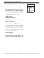
H8QIi+-F Quick Reference
Jumper
Description
Default Setting
JBT1
CMOS Clear
(See Section 2-7)
JCF1
Compact Flash Master/Slave
Closed (Master)
JI2C1/JI2C2
I2C to PCI-E Slot Enable/Disable
Both Closed (Enabled)
JPG1
VGA Enable/Disable
Pins 1-2 (Enabled)
JPL1
LAN 1/2 Enable/Disable
Pins 1-2 (Enabled)
JWD
Watch Dog
Pins 1-2 (Reset)
LED
Description
LAN Ports
LEDs for the LAN Ethernet ports
Dedicated IPMI LAN
LEDs for the dedicated IPMI LAN Ethernet port
LE1
LED for UID Button
Connector
Description
COM1/COM2
COM1 Serial Port/Header
FAN 1-9
Chassis/CPU Fan Headers
HT Connector
HT Connectors (2)
IDE#1
IDE Disk Drive Connector
IPMI LAN
Dedicated IPMI LAN Port
JD1
Speaker Header
JF1
Front Panel Connector
JIBTN1
RAIDKey for RAID 5 SAS support (optional for H8QIi+-F)
JL1
Chassis Intrusion Header
JOH1
Overheat Warning Header
JPI2C1
Power I2C Header
JPW1
24-pin Main ATX Power Connector
JPW2/3
+12V 8-pin CPU Power Connectors
JSMB1
System Management Bus Header (SMBus)
JWF1
Compact Flash Card Power Connector
JWOL1
Wake-On-LAN Header
LAN1/2
Gigabit Ethernet (RJ45) Ports
PS2 Mouse/Keyboard
PS2 Mouse/Keyboard connectors
SATA0 ~ SATA5
SATA Ports
T-SGPIO-1/TSGPIO-2
Serial General Purpose Input/Output Header for SATA
UID
Unit Identifier Button
USB0/1, USB4/5, USB2/3, USB6/7
Universal Serial Bus (USB) Ports, Type-A Ports and Headers
VGA
VGA Connector
Note: Jumpers not indicated are for test purposes only.
5-9
A+ SERVER AS-1041A-T2F User's Manual
5-6
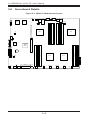
Serverboard Details
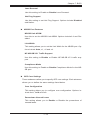
Figure 5-3. H8QIi+-F Motherboard Layout
COM1
VGA
KB/
MOUSE
FAN9
USB0/1
UID
LAN1/2
JWD1 JPG1
JSMB1 JPL1
BMC
IPMI_LAN
LE1
Intel
82576
FAN7-CPU4
FAN8-CPU4
DIMMD-2A
DIMMD-2B
DIMMD-1A
DIMMD-1B
DIMMC-1B
DIMMC-1A
DIMMC-2B
JI2C2
DIMMC-2A
SLOT6 PCI-E X16
JI2C1
CPU4
USB4
JBT1
JWOL1
COM2
AMD
SR5690
USB6/7
USB2/3
SATA0
SATA1
HT-CONNECTOR
USB5
AMD
SR5100
Battery
DIMMB-1B
DIMMB-1A
CPU2
DIMMB-2B
CPU1
DIMMB-2A
DIMMA-2A
DIMMA-2B
JIBTN1
DIMMA-1A
DIMMA-1B
T-SGPIO1
T-SGPIO2
SATA2
SATA3
SATA4
SATA5
CPU3
JD1
JF1
JPI2C1
JL1
JOH1
JPW3
JPW2
IDE#1
JWF1
JPW1
JCF1
FAN5
FAN6
FAN4-CPU1
FAN3-CPU2
FAN2
FAN1
5-10
Chapter 5: Advanced Serverboard Setup
5-7
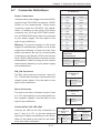
Connector Definitions
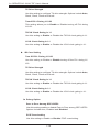
ATX Power 24-pin Connector
Pin Definitions
Power Connectors
A 24-pin main power supply connector(JPW1)
and two 8-pin CPU PWR connectors (JPW2/
JPW3) on the motherboard. These power
connectors meet the SSI EPS 12V specification. In addition to the 24-pin ATX power
connector, the 12V 8-pin CPU PWR connectors at JPW2/JPW3 must also be connected
to your power supply. See the table on the
right for pin definitions.
Warning: To prevent damage to the power
supply or motherboard, please use a power
supply that contains a 24-pin and two 8-pin
power connectors. Be sure to connect these
connectors to the 24-pin (JPW1) and the two
8-pin (JPW2,JPW3) power connectors on the
motherboard. Failure in doing so will void the
manufacturer warranty on your power supply
and motherboard.
Pin# Definition
Pin # Definition
13
+3.3V
1
+3.3V
14
-12V
2
+3.3V
15
COM
3
COM
16
PS_ON
4
+5V
17
COM
5
COM
18
COM
6
+5V
19
COM
7
COM
20
Res (NC)
8
PWR_OK
21
+5V
9
5VSB
22
+5V
10
+12V
23
+5V
11
+12V
24
COM
12
+3.3V
12V 8-pin PWR
Connector
Pin Definitions
Pins
Definition
1 through 4
Ground
5 through 8
+12V
Required Connection
PW_ON Connector
Power Button
Pin Definitions
(JF1)
The PW_ON connector is on pins 1 and 2 of
JF1. This header should be connected to the
chassis power button. See the table on the
right for pin definitions.
Pin# Definition
1
PW_ON
2
Ground
Reset Connector
Reset Button
Pin Definitions
(JF1)
The reset connector is located on pins 3 and
4 of JF1 and attaches to the reset switch on
the computer chassis. See the table on the
right for pin definitions.
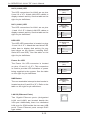
Overheat/Fan Fail LED (OH)
Connect an LED to the OH connection on
pins 7 and 8 of JF1 to provide advanced
warning of chassis overheating or fan failure.
Refer to the table on the right for pin definitions and status indicators.
5-11
Pin# Definition
3
Reset
4
Ground
OH/Fan Fail
LED
Pin Definitions
(JF1)
OH/Fan Fail
LED Status
State
Indication
Pin# Definition
Solid
Overheat
7
Vcc
Blinking
Fan fail
8
Control
A+ SERVER AS-1041A-T2F User's Manual
NIC2 (LAN2) LED
The LED connections for LAN2 are on pins
9 and 10 of JF1. Attach LAN LED cables to
display network activity. See the table on the
right for pin definitions.
NIC2 LED
Pin Definitions
(JF1)
Pin# Definition
9
Vcc
10
Ground
NIC1 (LAN1) LED
The LED connections for LAN1 are on pins
11 and 12 of JF1. Attach LAN LED cables to
display network activity. See the table on the
right for pin definitions.
NIC1 LED
Pin Definitions
(JF1)
Pin# Definition
11
Vcc
12
Ground
HDD LED
The HDD LED connection is located on pins
13 and 14 of JF1. Attach the hard drive LED
cable here to display disk activity (for any
hard drives on the system, including SAS,
Serial ATA and IDE). See the table on the
right for pin definitions
Power On LED
The Power On LED connector is located
on pins 15 and 16 of JF1. This connection
is used to provide LED indication of power
being supplied to the system. See the table
on the right for pin definitions.
NMI Button
The non-maskable interrupt button header is
located on pins 19 and 20 of JF1. Refer to the
table on the right for pin definitions.
LAN1/2 (Ethernet Ports)
Two Gigabit Ethernet ports (designated
LAN1 and LAN2) are located beside the
VGA port. Additionally, there is a dedicated
LAN poor for IPMI beside the two rear USB
ports. These Ethernet ports accept RJ45
type cables.
5-12
HDD LED
Pin Definitions
(JF1)
Pin# Definition
13
Vcc
14
HD Active
Power LED
Pin Definitions
(JF1)
Pin# Definition
15
5V Stby
16
Control
NMI Button
Pin Definitions
(JF1)
Pin# Definition
19
Control
20
Ground
Chapter 5: Advanced Serverboard Setup
Universal Serial Bus Ports
Two Universal Serial Bus ports (USB 2.0) are
located beside the Keyboard and Mouse PS2
ports. Two additional Type A ports (USB4/5)
are included on the motherboard. See the
table on the right for pin definitions.
Universal Serial Bus Ports
Pin Definitions (USB0/1, USB4/5)
USB0
Pin # Definition
USB1
Pin # Definition
1
+5V
1
+5V
2
PO-
2
PO-
3
PO+
3
PO+
4
Ground
4
Ground
USB Headers
Four USB 2.0 headers (USB2/3 and USB6/7)
are also included on the motherboard. These
may be connected to provide front side access. A USB cable (not included) is needed
for the connection. See the table on the right
for pin definitions.
Universal Serial Bus Headers
Pin Definitions (USB2/3, USB6/7)
USB2
Pin # Definition
USB3
Pin # Definition
1
+5V
1
+5V
2
PO-
2
PO-
3
PO+
3
PO+
4
Ground
4
Ground
5
Key
5
NC
Note: NC indicates no connection.
Fan Headers
Fan Header
Pin Definitions
This motherboard has eight fan headers
(Fan1 to Fan9). These 4-pin fans headers
are backward compatible with 3-pin fans.
However, fan speed control is available for
4-pin fans only. The fan speeds are controlled by the BIOS. See the table on the right
for pin definitions
Serial Ports
The COM1 serial port is located beside the
VGA port. Refer to the motherboard layout
for the location of the COM2 header. See the
table on the right for pin definitions.
Pin#
Definition
1
Ground
2
+12V
3
Tachometer
4
PWR Modulation
Serial Port Pin Definitions
(COM1/COM2)
Pin # Definition
Pin # Definition
1
DCD
6
DSR
2
RXD
7
RTS
3
TXD
8
CTS
4
DTR
9
RI
5
Ground
10
NC
Note: NC indicates no connection.
5-13
A+ SERVER AS-1041A-T2F User's Manual
SGPIO
The T-SGPIO1/ T-SGPIO2 (Serial General
Purpose Input/Output) headers provide a
bus between the SATA controller and the
backpane to provide SATA enclosure management functions. Connect the appropriate
cable from the backplane to the T-SGPIO1
header to utilize SATA management functions on your system.
SGPIO Header Pin Definitions
(T-SGPIO1/TSGPIO2)
(3SGPIO1/3SGPIO2))
Pin# Definition
Pin # Definition
1
NC
2
NC
3
Ground
4
Data
5
Load
6
Ground
7
NC
8
NC
Note: NC indicates no connection.
Likewise, the 3-SGPIO1/3-SGPIO2 headers
provide the same function between the SAS
controller and the backpane, and have the
same pin definitions.
SMBus Header
The header at SMBus is for the System Management Bus. Connect the appropriate cable
here to utilize SMB on the system. See the
table on the right for pin definitions.
SMBus Header
Pin Definitions
(SMBus)
Pin# Definition
1
Data
2
Ground
3
Clock
4
No Connection
Wake-On-LAN
The Wake-On-LAN header is designated
JWOL. See the table on the right for pin
definitions. You must have a LAN card with
a Wake-On-LAN connector and cable to use
the Wake-On-LAN feature.
Wake-On-LAN
Pin Definitions
(JWOL)
Pin# Definition
1
+5V Standby
2
Ground
3
Wake-up
Power I2C
Power I2C
Pin Definitions
(JPI2C)
2
The JPI2C1 header is for power I C, which
may be used to monitor the status of the power supply, fan and system temperature. See
the table on the right for pin definitions.
5-14
Pin# Definition
1
Data
2
Ground
3
Clock
4
NC
Chapter 5: Advanced Serverboard Setup
Chassis Intrusion
Chassis Intrusion
Pin Definitions (JL1)
A Chassis Intrusion header is located at JL1.
Attach the appropriate cable to inform you of
a chassis intrusion.
Pin# Definition
1
Battery voltage
2
Intrusion signal
Overheat LED
Overheat LED
Pin Definitions
(JOH1)
Connect an LED to the JOH1 header to provide warning of chassis overheating. See the
table on the right for pin definitions.
Pin# Definition
Power LED/Speaker
1
3.3V
2
OH Active
PWR LED Connector
Pin Definitions
On the JD1 header, pins 1~3 are used for
power LED indication, and pins 4-7 are for
the speaker. See the tables on the right for
pin definitions. If you wish to use the onboard
speaker, you should close pins 6~7 with a
jumper. Connect a cable to pins 4~7 of JD1
to use an external speaker.
Definition
Anode (+)
Pin2
Cathode (-)
Pin3
NA
Speaker Connector
Pin Definitions
ATX PS/2 Keyboard and PS/2 Mouse
Ports
The ATX PS/2 keyboard and PS/2 mouse are
located next to the Back Panel USB Ports
0~3 on the motherboard. See the table at
right for pin definitions.
Pin Setting
Pin 1
Pin Setting
Definition
Pins 4~7
External Speaker
Pins 6~7
Internal Speaker
PS/2 Keyboard/Mouse Pin
Definitions
PS2 Keyboard
PS2 Mouse
Pin# Definition
Pin# Definition
1
KB Data
1
Mouse Data
2
No
Connection
2
No
Connection
3
Ground
3
Ground
4
Mouse/KB
VCC (+5V)
4
Mouse/KB
VCC (+5V)
5
KB Clock
5
Mouse Clock
6
No Connection
6
No Connection
VCC: with 1.5A PTC (current limit)
5-15
A+ SERVER AS-1041A-T2F User's Manual
Unit Identifier Button
SW1 is a Unit Identifier (UID) button. There
is another UID button located on the control
panel. When you push either UID button,
both Rear UID and Front Panel UID Indicators will illuminate. Push either button again
to turn off both indicators. These UID indicators provide easy identification of a system
unit that may be in need of service.
JIBTN1 Header
(optional for H8QIi+-F)
A RAIDKey header, located at JIBTN1, provides RAID function support in order to use
RAID 5 SAS support.
Compact Flash Card PWR Connector
A Compact Flash Card Power Connector
is located at JWF1. For the Compact Flash
Card to work properly, you will need to enable with JCF1 and connect a Compact Flash
Card power cable to JWF1 first.
Video Connector
A Video (VGA) connector is located below
the COM Port on the IO backplane. This
connector is used to provide video and CRT
display.
5-16
UID Button
Pin Definitions
Pin#
Definition
1
Ground
2
Ground
3
Button In
4
Ground
Chapter 5: Advanced Serverboard Setup
5-8
Jumper Settings
To modify the operation of the
serverboard, jumpers can be used
to choose between optional settings.
Jumpers create shorts between two
pins to change the function of the
connector. Pin 1 is identified with
a square solder pad on the printed
circuit board. See the serverboard
layout pages for jumper locations.
Note: On a two-pin jumper, "Closed"
means the jumper is on both pins and
"Open" means the jumper is either on
only one pin or completely removed.
3
2
1
3
2
1
Connector
Pins
Jumper
Setting
CMOS Clear
JBT1 is used to clear CMOS (which will also clear any passwords). Instead of pins,
this jumper consists of contact pads to prevent accidentally clearing the contents
of CMOS.
To Clear CMOS
1. First power down the system and unplug the power cord(s).
2. With the power disconnected, short the CMOS pads with a metal object such
as a small screwdriver.
3. Remove the screwdriver (or shorting device).
4. Reconnect the power cord(s) and power on the system.
Note: Do not use the PW_ON connector to clear CMOS.
VGA Enable/Disable
JPG1 allows you to enable or disable the
VGA port. The default position is on pins 1
and 2 to enable VGA. See the table on the
right for jumper settings.
5-17
VGA Enable/Disable
Jumper Settings (JPG1)
Jumper Setting
Definition
Pins 1-2
Enabled
Pins 2-3
Disabled
A+ SERVER AS-1041A-T2F User's Manual
I2C to PCI-Express Slot
2
2
I2C to PCI-Express Slot
Jumper Settings
(JPI2C1/JPI2C2)
2
JI C1/JI C2 allows you to enable the I C bus
to communicate with the PCI-Express slot.
For the jumpers to work properly, please set
both jumpers to the same setting. If enabled,
both jumpers must be enabled. If disabled,
both jumpers must be disabled. See the table
on the right for jumper settings.
Jumper Setting Definition
Closed
Enabled
Open
Disabled
Watch Dog Enable/Disable
JWD enables the Watch Dog function, a
system monitor that takes action when a
software application freezes the system.
Jumping pins 1-2 will have WD reboot the
system if a program freezes. Jumping pins
2-3 will generate a non-maskable interrupt
for the program that has frozen. See the
table on the right for jumper settings. Watch
Dog must also be enabled in BIOS.
Compact Flash Master/Slave Select
A Compact Flash Master (Primary)/Slave
(Secondary) Select Jumper is located at
JCF1. Close this jumper to enable Compact
Flash Card. For the Compact Flash Card
or the Compact Flash Jumper (JCF1) to
work properly, you will need to connect the
Compact Flash Card power cable to JWF1
first. Refer to the board layout below for the
location.
LAN1/2 Enable/Disable
Change the setting of jumper JPL1 to enable
to enable or disable the LAN1 and LAN2
Ethernets ports. See the table on the right
for jumper settings. The default setting is
enabled.
5-18
Watch Dog
Jumper Settings (JWD)
Jumper Setting
Definition
Pins 1-2
Reset
Pins 2-3
NMI
Open
Disabled
Note: when Watch Dog is enabled, the user
must write their own application software to
disable the Watch Dog Timer.
Compact Flash Card Master/
Slave Select (JCF1)
Jumper Setting
Definition
Open
Slave (Secondary)
Closed
Master (Primary)
LAN1/2 En/Disable
Jumper Settings (JPL1)
Jumper Setting
Definition
Pins 1-2
Enabled
Pins 2-3
Disabled
Chapter 5: Advanced Serverboard Setup
5-9
Onboard Indicators
LAN LED
(Connection Speed Indicator)
LAN1/LAN2 LEDs
The Ethernet ports (located beside the VGA
port) have two LEDs. On each Gb LAN port,
one LED blinks to indicate activity while the
other may be green, amber or off to indicate
the speed of the connection. See the table
on the right for the functions associated with
the connection speed LED.
Dedicated IPMI LAN LEDs
LED Color
Definition
Off
10 MHz
Green
100 MHz
Amber
1 GHz
IPMI LAN Link LED (DP5001)
(Left) & Activity LED (Right)
A dedicated IPMI LAN is also included on the
H8QI6/i(+)(-F) serverboard (DP5001). The
amber LED on the right indicates activity,
while the green LED on the left indicates
the speed of the connection. See the table
at right for more information.
Color
Status
Definition
Link
(Left)
Green:
Solid
100 Mb/s
Activity
(Right)
Amber:
Blinking
Active
UID LED (LE1)
A rear UID LED Indicator, located at LE1,
works in conjunction with the rear UID switch
to provide easy identification for a unit that
might be in need of service. Refer to Page
2-13 for further UID details.
Power LED
DP (Un-numbered on board) is an Onboard
Power LED. When this LED is lit, it means
power is present on the serverboard. Be
sure to turn off the system and unplug the
power cord(s) before removing or installing
components.
5-19
Power LED
(DP4)
State
System Status
On
Standby power present
on motherboard
Off
No power connected
A+ SERVER AS-1041A-T2F User's Manual
5-10 IDE and SATA Drive Connections
Use the following information to connect the IDE hard disk drive cables.
•
•
A red mark on a wire typically designates the location of pin 1.
The 80-wire ATA100/66 IDE hard disk drive cable that came with your system
has two connectors to support two drives. This special cable should be used
to take advantage of the speed this new technology offers. The blue connector
connects to the onboard IDE connector interface and the other connector(s) to
your hard drive(s). Consult the documentation that came with your disk drive for
details on actual jumper locations and settings for the hard disk drive.
IDE Connectors
There are two IDE connectors (one blue
and one white) on the serverboard. IDE#1
(blue) is designated as the Primary IDE
drive. The white connector is designated as
the Secondary IDE drive and is reserved
for Compact Flash Card use only. (See the
note below.) See the table on the right for
pin definitions.
Note: The white slot is reserved for Compact
Flash Cards only. Do not use it for other
devices. If populated with a Compact Flash
Card, IDE#1 (the blue slot) will be available
for one device only. For the Compact Flash
Card to work properly, you will first need to
enable with JCF1 and connect a power cable
to JWF1.
IDE Drive Connector
Pin Definitions (IDE#1)
Pin#
Definition
1
Reset IDE
2
Ground
3
Host Data 7
4
Host Data 8
5
Host Data 6
6
Host Data 9
7
Host Data 5
8
Host Data 10
9
Host Data 4
10
Host Data 11
11
Host Data 3
12
Host Data 12
13
Host Data 2
14
Host Data 13
15
Host Data 1
16
Host Data 14
17
Host Data 0
18
Host Data 15
19
Ground
20
Key
21
DRQ3
22
Ground
23
I/O Write
24
Ground
25
I/O Read
26
Ground
27
IOCHRDY
28
BALE
29
DACK3
30
Ground
31
IRQ14
32
IOCS16
33
Addr1
34
Ground
35
Addr0
36
Addr2
37
Chip Select 0
38
Chip Select 1
39
Activity
40
Ground
SATA Ports
There are no jumpers to configure the SATA
ports, which are designated SATA0 through
SATA5. See the table on the right for pin
definitions.
5-20
Pin # Definition
SATA Ports Pin Definitions
(SATA0-SATA3)
Pin # Definition
Pin # Definition
1
Ground
5
2
TXP
6
RXP
3
TXN
7
Ground
4
Ground
RXN
Chapter 5: Advanced Serverboard Setup
5-11 Enabling SATA RAID
Now that the hardware is set up, you must install the operating system and the
SATA RAID drivers, if you wish to use RAID with your SATA drives. The installation
procedure differs depending on whether you wish to have the operating system
installed on a RAID array or on a separate non-RAID drive. See the instructions
below for details.
Serial ATA (SATA)
Serial ATA (SATA) is a physical storage interface that employs a single cable with a
minimum of four wires to create a point-to-point connection between devices. This
connection is a serial link that supports a SATA transfer rate from 150 MBps. The
serial cables used in SATA are thinner than the traditional cables used in Parallel
ATA (PATA) and can extend up to one meter in length, compared to only 40 cm for
PATA cables. Overall, SATA provides better functionality than PATA.
Installing the OS/SATA Driver
Before installing the OS (operating system) and SATA RAID driver, you must decide
if you wish to have the operating system installed as part of a bootable RAID array
or installed to a separate non-RAID hard drive. If on a separate drive, you may
install the driver either during or after the OS installation. If you wish to have the
OS on a SATA RAID array, you must follow the procedure below and install the
driver during the OS installation.
Building a Driver Diskette
You must first build a driver diskette from the Supermicro CD-ROM that was included
with the system. (You will have to create this disk on a computer that is already
running and with the OS installed.) Insert the CD into your CD-ROM drive and start
the system. A display as shown in Figure 5-6 will appear. Click on the icon labeled
"Build Driver Diskettes and Manuals" and follow the instructions to create a floppy
disk with the driver on it. Once it's been created, remove the floppy and insert the
installation CD for the Windows Operating System you wish to install into the CDROM drive of the new system you are about to configure.
5-21
A+ SERVER AS-1041A-T2F User's Manual
Enabling SATA RAID in the BIOS
Before installing the Windows Operating System, you must change some settings
in BIOS. Boot up the system and hit the <Del> key to enter the BIOS Setup Utlility.
After the Setup Utility loads,
1. Use the arrow keys to move to the Exit menu. Scroll down with the arrow
keys to the "Load Optimal Defaults setting and press <Enter>. Select "OK" to
confirm, then <Enter> to load the default settings.
2. Use the arrow keys to move to the "Advanced" menu, then scroll down to
"Chipset Configuration". Next enter "SourthBridge Configuration" and press
the <Enter> key. Once in this submenu, scroll down to "OnChip SATA Type"
and choose the "RAID" option (see Figure 5-4).
Figure 5-4. BIOS Setup Screen
3. Hit the <Esc> key twice and scroll to the Exit menu. Select "Save Changes
and Exit" and hit <enter>, then hit <Enter> again to verify.
4. After exiting the BIOS Setup Utility, the system will reboot. When prompted
during the startup, press the <CTRL+A> key when prompted to run the DotHill RAID Utility program (see Figure 5-5).
5-22
Chapter 5: Advanced Serverboard Setup
Using the Adaptec RAID Utility
The Adaptec® RAID Utility program is where you can define the drives you want
to include in the RAID array and the mode and type of RAID.
Figure 5-5. Adaptec RAID Utility Program Screen
Installing the RAID Driver During OS Installation
You may also use the procedure below to install the RAID driver during the Window's OS installation:
1. With the Windows OS installation CD in the CD-ROM drive, restart the
system.
2. When you see the prompt, hit the <F6> key to enter Windows setup.
3. Eventually a blue screen will appear with a message that begins "Windows
could not determine the type of one or more storage devices . . ." When you
see the screen, hit the <S> key to "Specify Additional Device", then insert the
driver diskette you just created into the floppy drive.
4. Highlight "Manufuacturer Supplied Hardware Support Disk" and hit the
<Enter> key.
5. Highlight the first "Adaptec RAID" driver shown and press the <Enter> key to
install it.
6. Press <Enter> again to continue with the Windows setup.
5-23
A+ SERVER AS-1041A-T2F User's Manual
2-12 Installing Drivers
The CD that came bundled with the system contains drivers, some of which must
be installed, such as the chipset driver. After inserting this CD into your CD-ROM
drive, the display shown in Figure 2-6 should appear. (If this display does not appear,
click on the My Computer icon and then on the icon representing your CD-ROM
drive. Finally, double click on the S "Setup" icon.)
Click the icons showing a hand writing on paper to view the readme files for each
item. Click the computer icons to the right of these items to install each item (from
top to the bottom) one at a time. After installing each item, you should reboot the
system before moving on to the next item on the list. The bottom icon with a CD
on it allows you to view the entire contents of the CD.
Figure 5-6. Driver/Tool Installation Display Screen
5-24
Chapter 5: Advanced Serverboard Setup
5-13 Configuring Supero Doctor III
The Supero Doctor III program is a Web-base management tool that supports
remote management capability. It includes Remote and Local Management tools.
The local management is called the SD III Client. The Supero Doctor III program
included on the CDROM that came with your serverboard allows you to monitor
the environment and operations of your system. Supero Doctor III displays crucial
system information such as CPU temperature, system voltages and fan status. See
the Figure below for a display of the Supero Doctor III interface.
Notes: The default User Name and the Password are ADMIN.
In the Windows OS environment, the Supero Doctor III settings take precedence
over the BIOS settings. When first installed, Supero Doctor III adopts the temperature threshold settings previously set in the BIOS. Any subsequent changes
to these thresholds must be made within Supero Doctor, since the SD III settings
override the BIOS settings. For the Windows OS to adopt the BIOS temperature
threshold settings, please change the SDIII settings to be the same as those set
in the BIOS.
Figure 5-5. Supero Doctor III Interface Display Screen (Health Information)
5-25
A+ SERVER AS-1041A-T2F User's Manual
Figure 5-6. Supero Doctor III Interface Display Screen (Remote Control)
Note: SD III Software Revision 1.0 can be downloaded from our Web site at: ftp://
ftp.supermicro.com/utility/Supero_Doctor_III/. You can also download SDIII User's
Guide at: http://www.supermicro.com/PRODUCT/Manuals/SDIII/UserGuide.pdf. For
Linux, it is still recommend that you use Supero Doctor II.
5-26
Chapter 6: Advanced Chassis Setup
Chapter 6
Advanced Chassis Setup
This chapter covers the steps required to install components and perform
maintenance on the SC818TQ+-1000 chassis. For component installation, follow
the steps in the order given to eliminate the most common problems encountered.
If some steps are unnecessary, skip ahead to the next step.
Tools Required: The only tool you will need to install components and perform
maintenance is a Philips screwdriver.
6-1
Static-Sensitive Devices
Electrostatic Discharge (ESD) can damage electronic components. To prevent
damage to any printed circuit boards (PCBs), it is important to handle them very
carefully.
The following measures are generally sufficient to protect your equipment from
ESD damage.
Precautions
•
•
•
Use a grounded wrist strap designed to prevent static discharge.
Touch a grounded metal object before removing any board from its antistatic
bag.
Handle a board by its edges only; do not touch its components, peripheral chips,
memory modules or gold contacts.
•
•
•
When handling chips or modules, avoid touching their pins.
Put the serverboard, add-on cards and peripherals back into their antistatic
bags when not in use.
For grounding purposes, make sure your computer chassis provides excellent
conductivity between the power supply, the case, the mounting fasteners and
the serverboard.
6-1
A+ SERVER AS-1041A-T2F User's Manual
Figure 6-1. Chassis: Front and Rear Views
Control
Panel
Power Supply
Hot-Swap Drive Bays (3)
LAN
Ports
USB
Ports
6-2
COM
Port
VGA
Port
PCI Slot
Dedicated IPMI
LAN Port
Control Panel
The control panel (located on the front of the chassis) must be connected to the
JF1 connector on the serverboard to provide you with system status indications. A
ribbon cable has bundled these wires together to simplify the connection. Connect
the cable from JF1 on the serverboard to the appropriate header on the Control
Panel PCB (printed circuit board). Make sure the red wire plugs into pin 1 on both
connectors. Pull all excess cabling out of the airflow path.
The control panel LEDs inform you of system status. See "Chapter 3: System
Interface" for details on the LEDs and the control panel buttons. Details on JF1 can
be found in "Chapter 5: Advanced Serverboard Installation."
6-3
System Cooling
Four 4-cm counter-rotating fans provide the cooling for the system. Each fan unit
is actually made up of two fans joined back-to-back, which rotate in opposite
directions. This counter-rotating action generates exceptional airflow and works to
dampen vibration levels.
It is very important that the chassis top cover is properly installed and making a
good seal in order for the cooling air to circulate properly through the chassis and
cool the components. See Figure 6-2.
6-2
Chapter 6: Advanced Chassis Setup
System Fan Failure
Fan speed is controlled by system temperature via a BIOS setting. If a fan fails, the
remaining fans will ramp up to full speed. Replace any failed fan at your earliest
convenience with the same type and model (the system can continue to run with
a failed fan).
Replacing a System Fan (Figure 6-2)
1. If the BIOS is not being utilized to determine which fan has failed, open the
top cover of the chassis while the system is running to locate the position of
the failed fan. Never run the server for an extended period of time with the
top cover open.
2. Turn off the power to the system and unplug the AC power cord.
3. Remove the failed fan's wiring from the backplane.
4. Remove the four pins securing the fan to the fan tray.
5. Lift the failed fan from the fan tray and out of the chassis.
6. Place the new fan into the vacant space in the fan tray, while making sure
the arrows on the top of the fan (indicating air direction) point in the same
direction as the arrows on the other fans in the same fan tray.
7. Reconnect the fan wires to the exact same chassis fan headers as the
previous fan.
8. Reconnect the AC power cord, power up the system and check that the fan is
working properly before replacing the chassis cover.
Figure 6-2. Removing a Fan from the Fan Tray
6-3
A+ SERVER AS-1041A-T2F User's Manual
6-4
Removing the Top Cover from the Chassis
Before installing any components, replacing chassis fans or accessing the
motherboard, you will first need to remove the top cove from the chassis.
Removing the Top Cover
1. Using a Philips screw driver, remove two screws from the top cover as shown
below in Figure 6-3.
2. Unlock and remove the thumb screw from the chassis.
3. Press the release tabs and slide the top cover out from the chassis.
Figure 6-3. Removing the Top Cover
133
1
1
2
21
11
Figure 6-4. Top Cover Removed
6-4
Chapter 6: Advanced Chassis Setup
6-5
Removing the Riser Card Bracket from the Chassis
Before installing the motherboard, you will need to remove the riser card bracket
from the chassis.
Removing the Riser Card Bracket
1. After removing the top cover from the chassis, use a Philips screw driver to
remove the two screws on the riser card bracket as shown in Figure 6-4.
2. Remove the riser card bracket from the chassis.
Figure 6-4. Removing the Riser Card Bracket from the Chassis
1
12
6-5
A+ SERVER AS-1041A-T2F User's Manual
6-6
Installing the Motherboard into the Chassis
After you've removed the chassis cover and the riser card bracket from the chassis,
you are ready to install the motherboard into the chassis.
Installing the Motherboard into the Chassis
1. Locate the mounting holes on the motherboard and the mounting holes on
the chassis.
2. Align the mounting holes on the motherboard against the corresponding
mounting holes on the chassis. Once aligned, place the motherboard on top
of the chassis.
3. Using a Philips screw driver, install a 6-32 screw into each mounting hole to
secure the motherboard onto the chassis.
Figure 6-6. Installing the Motherboard
13
1
12
4. Connect power cables to the power connectors on the motherboard as shown
below.
5. Connect fan cables to the fan headers on the motherboard as shown in
Figure 6-7.
6-6
Chapter 6: Advanced Chassis Setup
Figure 6-7. Connecting Fans and Power Cables
14
Power
Connectors
15
Fan Headers
6-7
Installing the CPU Air Shroud into the Chassis
After you have installed the CPU and the CPU Heatsink into the chassis, you will
need to install the CPU air shroud to prevent the processors from overheat.
Procedures
1. Before installing the air shroud, make sure that the CPU, the heatsink and
the memory modules are properly installed.
2. Align the CPU air shroud with the CPUs.
3. Once aligned, secure the CPU air shroud into the chassis with a 6-32 screw
as shown in Figure 6-8.
6-7
A+ SERVER AS-1041A-T2F User's Manual
4. Cover the chassis with the top cover.
5. Securely attach the top cover to the chassis with screws and the thumb
screw.
!
Warning: Do not operate the system without the top cover being properly
installed.
Figure 6-8. Installing the CPU Air Shroud
4
14
15
6-8
Chapter 6: Advanced Chassis Setup
6-9
Drive Bay Installation/Removal
Accessing the Drive Bays
Hard Drives: Because of their hotswap capability, you do not need to access the
inside of the chassis or power down the system to install or replace hard drives.
Proceed to the next section for instructions.
Peripheral Drives: The SC818TQ chassis includes space for a variety of peripheral
drive options, including a 2.5" hard disk drive, DVD-ROM or floppy drive. For a
complete listing of peripheral drive options, visit the Supermicro web site at:
http://www.supermicro.com/products/chassis/1U/818/SC818TQ-1400.cfm
Hard Drive Installation
The hard drives are mounted in drive carriers to simplify their installation and
removal from the chassis. These carriers also help promote proper airflow for
the drive bays. For this reason, even empty carriers without drives installed must
remain in the chassis.
Removing Hard Drive Carriers from the Chassis
1. Press the release button on the drive carrier. This extends the drive carrier
handle (Figure 6-9).
2. Use the handle to pull the drive carrier out of the chassis.
6-9
A+ SERVER AS-1041A-T2F User's Manual
Figure 6-9. Removing a Hard Drive Carrier
12
1
!
Warning: Except for short periods of time (swapping hard drives),
do not operate the server with the hard drive carriers removed.
6-10
Chapter 6: Advanced Chassis Setup
Installing a Hard Drive to the Hard Drive Carrier
1. Remove the two screws securing the dummy drive to the carrier.
2. Remove the dummy drive from the carrier.
3. Install a new drive into the carrier with the printed circuit board side facing
downward so that the mounting holes align with those in the carrier.
4. Secure the hard drive by tightening all six screws (Figure 6-10).
Installing a Hard Drive Carrier Into the Chassis
1. Insert the loaded hard drive carrier into the drive bay of the chassis
2. Push the drive carrier into the drive bay, pushing in the handle of the carrier
until it clicks into the locked position (Figure 6-11).
Figure 6-10. Installing a Hard Drive to the Carrier
Hard Drive
14
14
Drive Carrier
6-11
A+ SERVER AS-1041A-T2F User's Manual
Note: When installing the hard drive carrier that is next to the power supply, the
power supply handle must be lifted before extending the hard drive carrier handle,
or before inserting the hard drive carrier into the drive bay.
Figure 6-11. Installing/Removing the Carrier Next to the Power Supply
Peripheral Drive Installation
Installing or Replacing a Peripheral Drive
1. Unplug the main power cord to the chassis.
2. Unplug the power and data cables from the motherboard and/or backplane.
3. If you are adding a new drive: Remove the dummy tray from the drive bay
The mini-bezel can be removed by pulling out the hard drive beneath the
drive bay, then pulling the mini-bezel forward.
If you are replacing a drive: Locate the locking tab at the rear (left hand side
when viewed from the front) of the peripheral drive. Push the tab toward the
drive and push the drive unit out the front of the chassis.
4. Insert the new drive unit in the slot until the tab locks in place.
5. Reconnect the data and power cables.
6. Replace the chassis cover (replace the server in the rack, if necessary) and
power up the system.
6-12
Chapter 6: Advanced Chassis Setup
6-10 Checking the Air Flow
Checking the Server's Air Flow
1. Make sure there are no wires or other objects obstructing the airflow in and
out of the server. Pull all excess cabling out of the airflow path.
2. Do not operate the server without all drive carriers installed in the drive bays.
Use only recommended server parts.
3. The control panel LEDs inform you of the overall system status. See “Chapter
3 System Interface” for details on the LEDs and the control panel buttons.
6-11 Power Supply
The system includes a single 1400 watt power supply, which is auto-switching
capable. Power must be removed from the system when replacing the power
supply.
Power Supply Failure
If the power supply module fails, the system will shut down and you will need to
replace the module. Replacements can be ordered directly from Supermicro (see
contact information in the Preface).
As there is only one power supply module in the system, power must be completely
removed from the server before removing and replacing the power supply for
whatever reason.
Removing/Replacing the Power Supply (Figure 6-12)
4. Power down the server and unplug the AC power cord.
5. Push the release tab on the front of the power supply.
6. Pull the power supply out using the attached handle.
7. Replace the failed power module with the same model (See Appendix C).
8. Push the new power supply module into the power bay until you hear a click.
9. Reconnect the AC power cord and depress the power button on the control
panel to restart the system.
6-13
A+ SERVER AS-1041A-T2F User's Manual
Figure 6-12. Removing/Replacing the Power Supply
12
13
14
6-14
Chapter 7: BIOS
Chapter 7
BIOS
7-1
Introduction
This chapter describes the AMI BIOS Setup Utility for the H8QIi+-F. The AMI ROM
BIOS is stored in a Flash EEPROM and can be easily updated. This chapter describes the basic navigation of the AMI BIOS Setup Utility setup screens.
Starting BIOS Setup Utility
To enter the AMI BIOS Setup Utility screens, press the <Delete> key while the
system is booting up.
Note: In most cases, the <Delete> key is used to invoke the AMI BIOS setup screen.
There are a few cases when other keys are used, such as <F1>, <F2>, etc.
Each main BIOS menu option is described in this manual. The Main BIOS setup
menu screen has two main frames. The left frame displays all the options that can
be configured. Grayed-out options cannot be configured. Options in blue can be
configured by the user. The right frame displays the key legend. Above the key
legend is an area reserved for a text message. When an option is selected in the
left frame, it is highlighted in white. Often a text message will accompany it. (Note:
the AMI BIOS has default text messages built in. Supermicro retains the option to
include, omit, or change any of these text messages.)
The AMI BIOS Setup Utility uses a key-based navigation system called "hot keys".
Most of the AMI BIOS setup utility "hot keys" can be used at any time during the
setup navigation process. These keys include <F1>, <F10>, <Enter>, <ESC>, arrow keys, etc.
Note: Options printed in Bold are default settings.
How To Change the Configuration Data
The configuration data that determines the system parameters may be changed by
entering the AMI BIOS Setup utility. This Setup utility can be accessed by pressing
<Del> at the appropriate time during system boot.
7-1
A+ SERVER AS-1041A-T2F User's Manual
Starting the Setup Utility
Normally, the only visible Power-On Self-Test (POST) routine is the memory test.
As the memory is being tested, press the <Delete> key to enter the main menu of
the AMI BIOS Setup Utility. From the main menu, you can access the other setup
screens. An AMI BIOS identification string is displayed at the left bottom corner of
the screen below the copyright message.
Warning! Do not upgrade the BIOS unless your system has a BIOS-related
issue. Flashing the wrong BIOS can cause irreparable damage to the
system. In no event shall Supermicro be liable for direct, indirect, special,
incidental, or consequential damages arising from a BIOS update. If you
have to update the BIOS, do not shut down or reset the system while the
BIOS is updating. This is to avoid possible boot failure.
7-2
Main Setup
When you first enter AMI BIOS Setup Utility, you will see the Main Menu screen.
You can always return to the Main Menu by selecting the Main tab on the top of
the screen with the arrow keys.
The Main Menu screen provides you with a system overview, which includes the
version, built date and ID of the AMIBIOS, the type, speed and number of the
processors in the system and the amount of memory installed in the system.
System Overview: The following BIOS information will be displayed:
System Time/System Date
Use this option to change the system time and date. Highlight System Time or System Date using the arrow keys. Enter new values through the keyboard. Press the
<Tab> key or the arrow keys to move between fields. The date must be entered in
Day MM/DD/YY format. The time is entered in HH:MM:SS format. (Note: The time
is in the 24-hour format. For example, 5:30 P.M. appears as 17:30:00.)
7-2
Chapter 7: BIOS
4-3
Advanced Settings Menu
CPU Configuration
CPU Configuration
This displays static information on the Module Version, AGESA Version, Physical
Count and Logical Count for the system's processor(s) and clock.
CPU Information
This setting is used to select which physical CPU's information to display. Options
include Processor 0 or Processor 1. The information for the selected processor
includes Processor number, Revision, Cache L1/L2/L3, Speed, NB CLK, Able to
Change Frequency and uCode Patch Level.
Note: Zero is always the "Boot Strap Processor" or main CPU with all others
being "Application Processors".
GART Error Reporting
This option should remain disabled for normal operation. The driver developer
may enable this option for testing purposes. Options are Enabled or Disabled.
Microcode Update
This setting Enables or Disables microcode updating.
Secure Virtual Machine Mode
This setting is used to Enable or Disable SVM.
Power Now
This setting is used to Enable or Disable the AMD Power Now feature.
ACPI SRAT Table
This option Enables or Disables the building of the ACPI SRAT Table.
CPU Prefetching
Use this setting to Enable or Disable CPU prefetching.
IO Prefetching
Use this option to Enable or Disable IO prefetching.
Probe Filter
Use this option to set the initialization mode for the probe filter. Options include
Auto, Disabled and MP Mode.
7-3
A+ SERVER AS-1041A-T2F User's Manual
IDE Configuration
Onboard PCI IDE Controller
This setting allows you to Enable or Disable the PCI IDE controller.
Primary/Secondary/Third/Fourth IDE Master/Slave
LBA/Large Mode
LBA (Logical Block Addressing) is a method of addressing data on a disk
drive. The options are Disabled and Auto.
Block (Multi-Sector Transfer)
Block mode boosts IDE drive performance by increasing the amount of data
transferred. Only 512 bytes of data can be transferred per interrupt if block
mode is not used. Block mode allows transfers of up to 64 KB per interrupt.
Select "Disabled" to allow the data to be transferred from and to the device
one sector at a time. Select "Auto" to allows the data transfer from and to
the device occur multiple sectors at a time if the device supports it. The
options are Auto and Disabled.
PIO Mode
PIO (Programmable I/O) mode programs timing cycles between the IDE
drive and the programmable IDE controller. As the PIO mode increases,
the cycle time decreases. The options are Auto, 0, 1, 2, 3, and 4. Select
Auto to allow BIOS to auto detect the PIO mode. Use this value if the IDE
disk drive support cannot be determined. Select 0 to allow BIOS to use PIO
mode 0, which has a data transfer rate of 3.3 MBs. Select 1 to allow BIOS
to use PIO mode 1, which has a data transfer rate of 5.2 MBs. Select 2 to
allow BIOS to use PIO mode 2, which has a data transfer rate of 8.3 MBs.
Select 3 to allow BIOS to use PIO mode 3, which has a data transfer rate
of 11.1 MBs. Select 4 to allow BIOS to use PIO mode 4, which has a data
transfer rate of 16.6 MBs. This setting generally works with all hard disk
drives manufactured after 1999. For other disk drives, such as IDE CD-ROM
drives, check the specifications of the drive.
DMA Mode
Selects the DMA Mode. Options are Auto, SWDMA0, SWDMA1, SWDMA2,
MWDMA0. MDWDMA1, MWDMA2, UDMA0. UDMA1, UDMA2, UDMA3,
UDMA4 and UDMA5. (SWDMA=Single Word DMA, MWDMA=Multi Word
DMA, UDMA=UltraDMA.)
7-4
Chapter 7: BIOS
S.M.A.R.T.
Self-Monitoring Analysis and Reporting Technology (SMART) can help predict impending drive failures. Select "Auto" to allow BIOS to auto detect
hard disk drive support. Select "Disabled" to prevent AMI BIOS from using
the S.M.A.R.T. Select "Enabled" to allow AMI BIOS to use the S.M.A.R.T. to
support hard drive disk. The options are Disabled, Enabled, and Auto.
32-Bit Data Transfer
Select "Enabled" to activate the function of 32-Bit data transfer. Select "Disabled" to deactivate the function. The options are Enabled and Disabled.
Hard Disk Write Protect
Use this setting to Enable or Disable hard disk write protection for your system.
This is effective only if the device is accessed through the BIOS.
IDE Detect Timeout (Sec)
Use the +/- keys to adjust and select the time out for detecting ATA/ATAPI devices. The default value is 35.
ATA(PI) 80Pin Cable Detection
This option selects the mechanism used for detecting the installation of an 80-pin
ATA(PI) cable. Options include Host & Device, Host or Device.
Floppy Configuration
Floppy A
Use this option to select the type of floppy drive connected to the system for the
Floppy A. Options include Disabled, 360 KB 5 1/4, 1.2 MB 5 1/4, 720 KB 3.5,
1.44 MB 3.5 or 2.88 MB 3.5
Floppy B
Use this option to select the type of floppy drive connected to the system for the
Floppy B. Options include Disabled, 360 KB 5 1/4, 1.2 MB 5 1/4, 720 KB 3.5,
1.44 MB 3.5 or 2.88 MB 3.5
7-5
A+ SERVER AS-1041A-T2F User's Manual
PCI/PnP Configuration
Clear NVRAM
Select Yes to clear NVRAM during boot-up. The options are Yes and No.
Plug & Play O/S
Select Yes to allow the OS to configure Plug & Play devices. (This is not required
for system boot if your system has an OS that supports Plug & Play.) Select No
to allow AMIBIOS to configure all devices in the system.
PCI Latency Timer
This option sets the latency of all PCI devices on the PCI bus. Select a value
to set the PCI latency in PCI clock cycles. Options are 32, 64, 96, 128, 160,
192, 224 and 248.
Allocate IRQ to PCI VGA
Use this option to allocate IRQ to the PCI VGA card. Opiton include Yes and No.
Selecting Yes assigns IRQ to PCI VGA card if the card requests IRQ. Selecting
No means the system will not assign IRQ to the PCI VGA card even if the card
requests IRQ.
Pallette Snooping
This option Enables or Disables Pallette Snooping. If enabled, the system informs the PCI devices that an ISA graphics device is installed in the sytem so
the card will function normally.
PCI IDE Busmaster
Use this setting to Enable or Disable BIOS enabled uses of PCI Busmastering
for reading or writing to IDE drives.
Offboard PCI/ISA IDE Card
Some PCI IDE cards may require this option to be set to the PCI slot number
that is holding the card. The Auto setting works for most PCI IDE cards. Options include Auto, PCI Slot 1, PCI Slot , PCI Slot 3, PCI Slot 4, PCI Slot 5
and PCI Slot 6.
IRQ3 ~ IRQ15 Settings
These settings specify if IRQ is available to be used by PCI/PnP devices or is
reserved for use by legacy ISA devices. Options are Available or Reserved.
7-6
Chapter 7: BIOS
DMA Channel 0 ~ DMA Channel 7 Settings
These settings specify if a DMA Channel is available to be used by PCI/PnP
devices or is reserved for use by legacy ISA devices. Options are Available or
Reserved.
Reserved Memory Size
This option specifies the size of the memory block reserved for legacy ISA devices. Options include Disabled, 16k, 32k or 64k.
Onboard NIC Option ROM
This option Enables or Disables the onboard NIC option ROM.
Onboard LSI SAS Option ROM
This option Enables or Disables the onboard LSI SAS option ROM.
SuperI/O Configuration
Serial 1 Address
This option specifies the base I/O port address and Interrupt Request address
of serial port 1. Select "Disabled" to prevent the serial port from accessing any
system resources. When this option is set to Disabled, the serial port physically
becomes unavailable. Select "3F8/IRQ4" to allow the serial port to use 3F8 as its
I/O port address and IRQ 4 for the interrupt address. Options include Disabled,
3F8/IRQ4, 3E8/IRQ4 and 2E8/IRQ3
Serial 2 Address
This option specifies the base I/O port address and Interrupt Request address
of serial port 2. Select "Disabled" to prevent the serial port from accessing any
system resources. When this option is set to "Disabled", the serial port physically
becomes unavailable. Select "2F8/IRQ3" to allow the serial port to use 2F8 as its
I/O port address and IRQ 3 for the interrupt address. Options include Disabled,
2F8/IRQ3, 3E8/IRQ4 and 2F8/IRQ3.
Serial Port Mode
This sets the serial port mode for your system. Options include Normal,
IrDA and ASK IR.
Restore on AC Power Loss
This sets the action that occurs when an AC power loss occurs. Options include
Power Off, Power On and Last State.
7-7
A+ SERVER AS-1041A-T2F User's Manual
Watch Dog Timer
This sets the Watch Dog Timer. Options include Enabled or Disabled.
Hyper-Transport Configuration
NODE0: PCI-X2 HT Link
Link Speed
The Hyper Transport link will run at this speed if it is slower than or equal
to the system clock speed. Options include 1 GHz and Auto.
Link Width
Hyper Transport runs at this width. Options include Auto, 4 Bit, 8 Bit
and 16 Bit.
NODE0: NODE1 HT Link Speed
Link Speed
The Hyper Transport link will run at this speed if it is slower than or
equal to the system clock speed and what the board is capable. Options
include 1 GHz and Auto.
NODE0: NODE1 HT Link Width
Link Width
Hyper Transport runs at this width. Options include Auto, 4 Bit, 8 Bit
and 16 Bit.
Chipset Configuration
NorthBridge Configuration
Memory Configuration
Bank Interleaving
Select Auto to automatically enable a bank-interleaving memory scheme
when this function is supported by the processor. The options are Auto
and Disabled.
7-8
Chapter 7: BIOS
Channel Interleaving
Selects the channel-interleaving memory scheme when this function is
supported by the processor. The options are Disabled, Address Bits 6,
Address Bits 12, XOR of Address Bits [20:16, 6] and XOR of Address
Bits [20:16, 9].
Mem Clk Tristate C3/ALTVID
Use this setting to Enable or Disable memory clock tristate during C3
and ALT VID.
Memory Hole Remapping
When "Enabled", this feature enables hardware memory remapping
around the memory hole. Options are Enabled and Disabled.
CS Sparing
This setting will reserve a spare memory rank in each node when enabled. Options are Enable and Disable.
DCT Unganged Mode
This setting enables unganged DRAM mode (64-bit). Options are Auto
(ganged mode) and Always (unganged mode).
Power Down Enable
This setting enables or disables DDR power down mode. Options are
Enabled and Disabled.
Power Down Mode
This sets the power down mode. Options are Channel and Chip
Select.
ECC Configuration
ECC Mode
This submenu affects the DRAM scrub rate based on its setting. Options
include Disabled, Basic, Good, Super, Max and User. Selecting User
activates the other options for user setting.
7-9
A+ SERVER AS-1041A-T2F User's Manual
DRAM ECC Enable
This setting allows hardware to report and correct memory errors
automatically, maintaining system integrity. Options are Enabled or
Disabled.
DRAM Scrub Redirect
This setting allows the system to correct DRAM ECC errors immediately
when they occur, even if background scrubbing is off. Options are Enabled or Disabled.
4-Bit ECC Mode
Allows the user to enabled 4-bit ECC mode (also known as ECC Chipkill).
Options are Enabled and Disabled.
DRAM BG Scrub
Corrects memory errors so later reads are correct. Options are Disabled
and various times in nanoseconds and microseconds. The default is
163.8us.
Data Cache BG Scrub
Allows L1 cache RAM to be corrected when idle. Options are Disabled
and various times in nanoseconds and microseconds. The default is
2.56us.
L2 Cache BG Scrub
Allows L2 cache RAM to be corrected when idle. Options are Disabled
and various times in nanoseconds and microseconds. The default is
2.56us.
L3 Cache BG Scrub
Allows L3 cache RAM to be corrected when idle. Options are Disabled
and various times in nanoseconds and microseconds. The default is
2.56us.
DRAM Timing Configuration
Memory Clock Mode
This setting specifies the memory clock mode. Options are Auto, Limit
and Manual.
7-10
Chapter 7: BIOS
DRAM Timing Mode
This setting specifies the DRAM timing mode. Options are Auto and
DCT0, DCT1 and Both.
Alternate VID
Specify the alternate VID while in low power states. Options are Auto
and various voltages from .800V to 1.050V in increments of .025V.
Memory Timing Parameters
This selects the which node's timing parameters to display. Options are
CPU Node 0 or CPU Node 1.
SouthBridge Configuration
OHCI/EHCI HC Device Functions
These settings allow you to either Enable or Disable functions for OHCI or
EHCI bus devices.
On Chip SATA Channel
This setting allows you to Enable or Disable the OnChip SATA channel.
On Chip SATA Type
Use this setting to set the On Chip SATA type. Options include
Native IDE, RAID, AHCI and Legacy IDE.
SATA IDE Combined Mode
This setting allows you to Enable or Disable the SATA IDE combined
mode.
PATA Channel Configuration
This allows you to set PATA channel configuration. Options include SATA
as Primary or SATA as secondary.
Power Saving Features
Use this option to Enable or Disable power down saving features in the
Southbridge chipset. This feature should be enabled for mobile systems
and disabled for desktop systems. See the AMD SB700 Power Saving
document for more details.
7-11
A+ SERVER AS-1041A-T2F User's Manual
RD890 Configuration
PCI Express Configuration
Port Features
This submenu allows you to set the features for Ports 02 through 13 in
the system. Each port submenu allows you to define the same settings
below.
Gen 2 High Speed Mode
This setting allows you to set the Gen 2 high-speed mode. Options
include Auto, Disabled, Software Initiated and Advertised RC.
Link ASPM
Use this setting to configure the Link ASPM. Options include Disabled, L0s, L1, L0s & L1, L0 Downstream and L0 Downstream
+ L1.
Note: For ATI GFx Card M2x use L1 only. For ATI GFx Card M5x
use both L0s & L1.
Link Width
Use this setting to configure the Link Width. Options include Auto,
x1, x2, x4, x8 and x16.
Slot Power Limit, W
Use this setting to configure the Slot Power Limit power. The user can
adjust this value using the + and - keys. The default is 75.
Compliance Mode
This setting allows you to Enable or Disable the Compliance Mode.
Remap Port Device Number
This setting allows you remap the Port Device number. Options include Auto and port numbers between 2 and 13.
L1 Immediate ACK
This setting allows you to Enable or Disable L1 ACK. When enabled,
the L1 will be ACK'd immediately.
7-12
Chapter 7: BIOS
Lane Reversal
Use this setting to Enable or Disable Lane Reversal.
Hot Plug Support
Use this setting to set Hot Plug Support. Options include Disabled
and Native.
NB-SB Port Features
NB-SB Link APSM
Use this to set the NB-SB Link ABSM. Options include L1 and Disabled.
Link Width
This setting allows you to set the Link Width for the NB-SB port. Options include Auto, x1, x2 and x4.
NP NB-SB VC1 Traffic Support
Use this setting to Disable or Enable NP NB-SB VC1 traffic support.
Compliance Mode
Use this setting to Enable or Disable Compliance Mode for the NBSB port.
GPP Core Settings
These submenus allow you to specify GPP core settings. Each submenu
allows you to define the same settings listed below.
Core Configuration
This setting allows you to configure core configuration. Options include Auto, 1x16 and 2x8.
Powerdown Unused Lanes
This setting allows you to Enable or Disable the powerdown of
unused lanes.
7-13
A+ SERVER AS-1041A-T2F User's Manual
TX Drive Strength
Use this setting to configure TX drive strength. Options include Auto,
26mA, 20mA, 22mA and 24mA.
Turnoff PLL During L1/L23
This setting allows you to Enable or Disable turning off PLL during
L1/L23.
TXCLK Clock Gating in L1
Use this setting to Enable or Disable the TXCLK clock gating in L1.
LCLK Clock Gating in L1
Use this setting to Enable or Disable the LCLK clock gating in L1.
SB Core Setting
Turn Off PLL During L1/L23
Use this setting to Enable or Disable turning off the PLL during L1/
L23.
TX Drive Strength
Use this setting to configure TX drive strength. Options include Auto,
26mA, 20mA, 22mA and 24mA.
TXCLK Clock Gating in L1
Use this setting to Enable or Disable the TXCLK clock gating in L1.
LCLK Clock Gating in L1
Use this setting to Enable or Disable the LCLK clock gating in L1.
Debug Option
Peer to Peer Among GPP1/GPP2
Use this setting enable or disable Peer to Peer among GPP1/GPP2.
Options include Auto, Enabled and Disabled.
PCIE Overclocking
Use this setting to Enable or Disable PCIE overclocking.
7-14
Chapter 7: BIOS
Reset to Training Delay (ms)
Use the +/- keys to change the reset to training delay time setting.
The default is 2.
Receiver Detection Pooling (ms)
Use the +/- keys to change the receiver detection pooling time
setting. The default is 40.
Hide Unused PCIE P2P Bridges
Use this setting to Enable or Disable the hiding of unused PCIE
P2P bridges.
GFX Card Workaround
This setting allows you to Enable or Disable the GFX Card
workaround on your system.
Debug Bus Configuration
PCIE Debug Bus
This setting Enables or Disables PCIE debugging of the bus.
Hyper Transport Configuration
HT Extended Address
This setting allows you to Enable or Disable the HT extended address.
Options include Enabled, Disabled and Auto.
HT3 Link Power State
This setting allows you to configure the HT3 Link power state. Options
include Auto, LS0, LS1, LS2 and LS3.
Unit ID Clumping
Use this setting to configure Unit ID clumping. Options include Disabled,
Auto, UnitID 2/3, UnitID B/C and UnitID 2/3 & B/C.
HT Link Tristate
This setting allwos you to configure the HT Link Tristate. Options include
Auto, Disabled, CAD/CTL and CAD/CTL/CLK.
7-15
A+ SERVER AS-1041A-T2F User's Manual
NB Deemphesis Level
Use this to set the NB deemphesis level. Options include Disabled, 0.4
dB, 1.32 dB, -2.08dB, 3.1 dB, 4.22 dB, 5.50 dB and 7.05 dB.
Debug Option
NB Transmitter Attenuation
Use this to set the NB Transmitter Attenuation by using the +/- keys
to change the number. The default number is 00.
CPU Transmitter Attenuation
Use this to set the CPU Transmitter Attenuation by using the the +/keys to change the number. The default number is 00.
CPU Deemphesis Level
Use this to set the CPU deemphesis level. Options include Disabled,
3dB, 6dB and 8dB.
NB & CPU HT Time Margining
Use this to Enable or Disable NB and CPU HT time margining.
IOMMU
This setting is used to disable or set the GART size in systems without AGP.
Options include AGP Present, Disabled, 32 MB, 64 MB, 128 MB, 256 MB,
512 MB and 1 GB.
Primary Video Controller
Use this setting to specify the primary video controller boot order. Options include
PCIE-GPP1-GPP2-GPP3a-PCI, PCIE-GPP2-GPP1-GPP3a-PCI, PCIE-GPP3aGPP1-GPP2-PCI or PCI-PCIE-GPP1-GPP2-GPP3a.
PCI Spread Spectrum
Use this setting to Enable or Disable PCI Spread Spectrum in the system.
Debug Option
Memory Decod on Sec. 6FX
Use this option to set memory decod on sector 6FX. Options are Disabled
or Force.
7-16
Chapter 7: BIOS
IOC Peer-to-Peer Mode
Use this option to set the IOC peer-to-peer mode. Options include Auto,
Default, Mode1 and Mode2
Northbridge Interrupt Pin
This option Enables or Disables the Northbridge Interrupt Pin.
ACPI Configuration
Advanced ACPI Configuration
ACPI Version Features
Use this setting the determine which ACPI version to use. Options are ACPI
v1.0, ACPI v2.0 and ACPI v3.0.
ACPI APIC Support
Determines whether to include the ACPI APIC table pointer in the RSDT
pointer list. The available options are Enabled and Disabled.
AMI OEMB Table
This setting specifies whether to include the OEMB table pointer to the R(X)
SOT pointer lists. Options include Enabled or Disabled.
Headless Mode
Use this setting to Enable or Disable headless operation mode through
ACPI.
IPMI Configuration
This menu shows static information about the IPMI firmware revision and status of
the BMC, as well as options for IPMI configuration.
View BMC System Event Log
Pressing the Enter key will open the following settings. Use the "+" and "-" keys
to navigate through the system event log.
Clear BMC System Event Log
Selecting this and pressing the Enter key will clear the BMC system event log.
7-17
A+ SERVER AS-1041A-T2F User's Manual
Set LAN Configuration
Use the "+" and "-" keys to choose the desired channel number. This displays
Channel Number and Channel Number Status information.
IP Address
This submenu sets the IP address source as either Static or DHCP. Selecting Static allows you to manually set the IP Address, Subnet Mask and
Gateway Address.
In the field provided here enter the IP address in the decimal form of xxx.
xxx.xxx.xxx with xxx having a value of less than 256 and in decimal form
only The IP address and current IP address in the BMC are shown.
MAC Address
In the field provided here enter the MAC address in the hex form of xx.xx.
xx.xx.xx.xx with xx in hex form only. The current MAC address in the BMC
is shown.
Subnet Mask
In the field provided here enter the Subnet address in the decimal form of
xxx.xxx.xxx.xxx with xxx having a value of less than 256 and in decimal form
only. The current subnet address in the BMC is shown.
Gateway Address
In the field provided here enter the Gateway address in the decimal form
of xxx.xxx.xxx.xxx with xxx having a value of less than 256 and in decimal
form only. The current Gateway address in the BMC is shown.
MPS Configuration
MPS Revision
This option allows you to set the MPS revision for your system. Options include
revision 1.1 and 1.4.
7-18
Chapter 7: BIOS
PCI Express Configuration
Active State Power Management
This setting allows you to Enable/Disable PCI Express L0s and L1 link power
status.
Remote Access Configuration
Remote Access
Use this option to Enable or Disable Remote Access in your system. If enabled,
the settings below will appear.
Serial Port Number
Use this setting to select the serial port for console redirection. Options include
COM1, COM2 or COM3*. The displayed base address and IRQ for the serial
port changes to reflect the selection you make.
Note: Make sure the selected port is enabled.
Serial Port Mode
Selects the serial port settings to use. Options are (115200 8, n, 1), (57600 8,
n, 1), (38400 8, n, 1), (19200 8, n, 1) and (09600 8, n, 1).
Flow Control
Selects the flow control to be used for console redirection. Options are None,
Hardware and Software.
Redirection After BIOS POST
Options are Disable (no redirection after BIOS POST), Boot Loader (redirection
during POST and during boot loader) and Always (redirection always active).
Note that some OS's may not work with this set to Always.
Terminal Type
Selects the type of the target terminal. Options are ANSI, VT100 and VTUTF8.
VT-UTF8 Combo Key Support
Allows you to Enable or Disable VT-UTF8 combination key support for ANSI/
VT100 terminals.
7-19
A+ SERVER AS-1041A-T2F User's Manual
Sredir Memory Display Delay
Use this setting to set the delay in seconds to display memory information. Options are No Delay, 1 sec, 2 secs and 4 secs.
USB Configuration
This submenu displays the Module Version and lists the USB devices that are
enabled as well as the following options.
Legacy USB Support
Select "Enabled" to enable the support for USB Legacy. Disable Legacy support if there are no USB devices installed in the system. "Auto" disabled Legacy
support if no USB devices are connected. The options are Disabled, Enabled
and Auto.
USB 2.0 Controller Mode
Use this setting to configure the USB 2.0 Controller in either Hi-Speed (480 Mps)
or Full Speed (12 Mps) mode.
BIOS EHCI Hand Off
This is a workaround for OS's without EHCI hand-off support. The EHCI ownership change should be claimed by the EHCI driver. Options are Enabled or
Disabled.
USB Mass Storage Device Configuration
This submenu is used to configure USB mass storage class devices.
USB Mass Storage Reset Delay
Use this option to set the number of seconds POST waits for the USB mass
storage device after the Start Unit command. Options include 10, 20, 30
and 40 seconds.
Emulation Type
This sets the emulation type for USB mass storage devices. If Auto, USB
devices less than 530 MB will be emulated as Floppy and remaining as Hard
Disk drive. The Force FDD option can be used to force a HDD formatted
drive to boot as an FDD (example: ZIP drive). Options include Auto, Floppy,
Forced FDD, Hard Disk and CD-ROM.
7-20
Chapter 7: BIOS
4-5
Boot Settings Menu
BIOS Settings Configuration
Quick Boot
If Enabled, this option will skip certain tests during POST to reduce the time
needed for the system to boot up. The options are Enabled and Disabled.
Quiet Boot
If Disabled, normal POST messages will be displayed on boot-up. If Enabled,
this display the OEM logo instead of POST messages.
Add On ROM Display Mode
This option sets the display mode for Option ROM. The options are Force BIOS
or Keep Current.
Bootup Num Lock
This option selects the power-on state for the NUM lock to either On or Off.
PS/2 Mouse Support
Use this option to select support for the PS/2 mouse. Options are Disabled,
Enabled or Auto.
Wait for F1 if Error
This setting controls the system response when an error is detected during the
boot sequence. When enabled, BIOS will stop the boot sequence when an error
is detected, at which point you will need to press the F1 button to re-enter the
BIOS setup menu. The options are Enabled and Disabled.
Hit 'DEL' Message Display
Use this option to Enable or Disable the "Press DEL to run setup" message in
POST.
Interrupt 19 Capture
Select Enabled to allow ROMs to trap Interrupt 19. The options are Enabled
and Disabled.
Boot Device Priority
This feature allows you to prioritize the boot sequence from the list of available
devices. A device that is in parenthesis has been disabled in the corresponding
type menu.
7-21
A+ SERVER AS-1041A-T2F User's Manual
Hard Disk Drives
This feature allows you to specify the boot sequence from the list of available hard
disk drives. A device that is in parenthesis has been disabled in the corresponding
type menu.
CD/DVD Drives
This feature allows you to specify the boot sequence from the list of available CD/
DVD drives. A device that is in parenthesis has been disabled in the corresponding type menu.
Removable Drives
This feature allows you to specify the boot sequence from the list of available
removable drives. A device that is in parenthesis has been disabled in the corresponding type menu.
4-6
Security Menu
AMI BIOS provides a Supervisor and a User password. If you use both passwords,
the Supervisor password must be set first.
Change Supervisor Password
Select this option and press <Enter> to access the sub menu, and then type in
the password.
Change User Password
Select this option and press <Enter> to access the sub menu, and then type in
the password.
Boot Sector Virus Protection
This option is near the bottom of the Security Setup screen. Select "Disabled" to
deactivate the Boot Sector Virus Protection. Select "Enabled" to enable boot sector
protection. When "Enabled", AMI BIOS displays a warning when any program (or
virus) issues a Disk Format command or attempts to write to the boot sector of the
hard disk drive. The options are Enabled and Disabled.
7-22
Chapter 7: BIOS
4-8
Exit Menu
Select the Exit tab from AMI BIOS Setup Utility screen to enter the Exit BIOS Setup
screen.
Save Changes and Exit
When you have completed the system configuration changes, select this option
to leave BIOS Setup and reboot the computer, so the new system configuration
parameters can take effect. Select Save Changes and Exit from the Exit menu and
press <Enter>.
Discard Changes and Exit
Select this option to quit BIOS Setup without making any permanent changes to the
system configuration and reboot the computer. Select Discard Changes and Exit
from the Exit menu and press <Enter>.
Discard Changes
Select this option and press <Enter> to discard all the changes and return to AMI
BIOS Utility Program.
Load Optimal Defaults
To set this feature, select Load Optimal Defaults from the Exit menu and press
<Enter>. Then Select "OK" to allow BIOS to automatically load the Optimal Defaults
as the BIOS Settings. The Optimal settings are designed for maximum system
performance, but may not work best for all computer applications.
Load Fail-Safe Defaults
To set this feature, select Load Fail-Safe Defaults from the Exit menu and press
<Enter>. The Fail-Safe settings are designed for maximum system stability, but not
maximum performance.
7-23
A+ SERVER AS-1041A-T2F User's Manual
Notes
7-24
Appendix A: BIOS Error Beep Codes
Appendix A
BIOS Error Beep Codes
During the POST (Power-On Self-Test) routines, which are performed each time
the system is powered on, errors may occur.
Non-fatal errors are those which, in most cases, allow the system to continue the
boot-up process. The error messages normally appear on the screen.
Fatal errors are those which will not allow the system to continue the boot-up procedure. If a fatal error occurs, you should consult with your system manufacturer
for possible repairs.
These fatal errors are usually communicated through a series of audible beeps. The
numbers on the fatal error list (on the following page) correspond to the number
of beeps for the corresponding error. All errors listed, with the exception of Beep
Code 8, are fatal errors.
A-1 AMIBIOS Error Beep Codes
Beep Code
Error Message
Description
1 beep
Refresh
Circuits have been reset (Ready to power up)
5 short, 1 long
Memory error
No memory detected in system
1 long, 8 short
Video error
Video adapter disabled or missing
A-1
A+ SERVER 6016T-GTF/GIBXF/GIQXF User's Manual
Notes
A-2
Appendix B: Installing Windows
Appendix B
Installing Windows
After all hardware components have been installed, you must first configure RAID
Settings before you install the Windows OS and other software drivers. To configure
RAID settings, please refer to RAID Configuration User Guides posted on our web
site at www.supermicro.com/support/manuals.
Note: The following OS installation instructions are written for the Windows XP/2003
OS only. If you have the Windows 2008 or Windows Vista OS, please follow the
instructions displayed on your screen to install the OS.
B-1 Installing Windows to a RAID System
1. Insert Microsoft's Windows XP/Windows 2003 Setup CD in the CD-ROM drive
and the system will start booting up from CD.
2. Press the <F6> key when the message "Press F6 if you need to install a third
party SCSI or RAID driver" displays.
3. When the Windows XP/Windows 2003 Setup screen appears, press "S" to
specify additional device(s).
4. Insert the driver diskette you created in Section 5-11, Building a Driver
Diskette, into Drive A: and press the <Enter> key.
5. Highlight "Manufuacturer Supplied Hardware Support Disk" and hit the
<Enter> key.
6. Highlight the first "Adaptec RAID" driver shown and press the <Enter> key to
install it. Soon a similar blue screen will appear again.
7. Again hit the <S> key, then highlight the second item, "nForce Storage
Controller" and press the <Enter> key, then <Enter> again to continue with
the Windows setup.
8. Press the <Enter> key to continue the installation process. (If you need to
specify any additional devices to be installed, do it at this time.) Once all
devices are specified, press the <Enter> key to continue with the installation.
B-1
A+ SERVER AS-1041A-T2F User's Manual
9. From the Windows XP/Windows 2003 Setup screen, press the <Enter> key.
The XP/2003 Setup will automatically load all device files and then, continue
the Windows XP/Windows 2003 installation.
10. After the Windows XP/Windows 2003 OS Installation has completed, the
system will automatically reboot.
B-2 Installing Windows to a Non-RAID System
1. Insert Microsoft's Windows OS Setup CD in the CD-ROM drive and the
system will start booting up from the CD.
2. Continue with the installation. The Windows OS Setup screen will display.
3. From the Windows OS Setup screen, press the <Enter> key. The OS Setup
will automatically load all device files and then continue with the Windows
installation.
4. After the installation has completed, the system will automatically reboot.
5. Insert the Supermicro Setup CD that came with your system into the CDROM drive during system boot and the main screen will display.
B-2
Appendix C: System Specifications
Appendix C
System Specifications
Processors
Four AMD® Opteron 8300/8400 series processors in Socket F type sockets.
Note: please refer to our website for details on supported processors.
Chipset
AMD SR5690 (North Bridge) and SP5100 (South Bridge) chipsets
BIOS
16 Mb AMIBIOS® SPI Flash ROM
Memory Capacity
Sixteen single/dual channel DIMM slots supporting up to 128 GB of DDR2800/667/533 registered ECC SDRAM
Note: interleaved memory requires DIMMs to be installed in pairs - refer to Section 5-6 for
details.
Serial ATA Controller
AMD SP5100 on-chip controller supports six 3 Gb/s Serial ATA
(RAID 0, 1 and 10)
SATA Drive Bays
Three hot-swap drive bays to house standard SATA drives
PCI Expansion
One (1) PCI-Express x16 slot
One (1) HTx Connector (Optional)
Serverboard
H8QIi+-F
Dimensions (all): 6.5 x 16.4 in (165 x 417 mm)
C-1
A+ SERVER AS-1041A-T2F User's Manual
Chassis
SC818TQ+-1000 (1U rackmount)
Dimensions: (WxHxD) 17.2 x 1.7 x 28.2 in. (437 x 43 x 716 mm)
Weight
Gross (Bare Bone): 47 lbs. (21.4 kg.)
System Cooling
Six 40x56mm counter-rotating cooling fans (fan speed controlled by BIOS
setting)
System Input Requirements
AC Input Voltage: 100-240 VAC
Rated Input Current: 7A (100V) to 15 (240V)
Rated Input Frequency: 50-60 Hz
Power Supply
Rated Output Power: 1000W w/PFC (Part# PWS-1K01-1R)
Rated Output Voltages: +12V (83A), +5Vsb (4A)
Operating Environment
Operating Temperature: 10º to 35º C (50º to 95º F)
Non-operating Temperature: -40º to 70º C (-40º to 158º F)
Operating Relative Humidity: 8% to 90% (non-condensing)
Non-operating Relative Humidity: 5 to 95% (non-condensing)
C-2
Appendix C: System Specifications
Regulatory Compliance
Electromagnetic Emissions: FCC Class A, EN 55022 Class A, EN 61000-3-2/-33, CISPR 22 Class A
Electromagnetic Immunity: EN 55024/CISPR 24, (EN 61000-4-2, EN 61000-4-3,
EN 61000-4-4, EN 61000-4-5, EN 61000-4-6, EN 61000-4-8, EN 61000-4-11)
Safety: CSA/EN/IEC/UL 60950-1 Compliant, UL or CSA Listed (USA and
Canada), CE Marking (Europe)
California Best Management Practices Regulations for Perchlorate Materials:
This Perchlorate warning applies only to products containing CR (Manganese
Dioxide) Lithium coin cells. “Perchlorate Material-special handling may apply.
See www.dtsc.ca.gov/hazardouswaste/perchlorate”
C-3
A+ SERVER AS-1041A-T2F User's Manual
Notes
(continued from front)
The products sold by Supermicro are not intended for and will not be used in life support systems,
medical equipment, nuclear facilities or systems, aircraft, aircraft devices, aircraft/emergency communication devices or other critical systems whose failure to perform be reasonably expected to
result in significant injury or loss of life or catastrophic property damage. Accordingly, Supermicro disclaims any and all liability, and should buyer use or sell such products for use in such ultra-hazardous
applications, it does so entirely at its own risk. Furthermore, buyer agrees to fully indemnify, defend
and hold Supermicro harmless for and against any and all claims, demands, actions, litigation, and
proceedings of any kind arising out of or related to such ultra-hazardous use or sale.
C-4