1
L2 / L3 Switches
VLAN
Configuration Guide
Revision 1.0
VLAN Configuration Guide
The information in this USER’S MANUAL has been carefully reviewed and is believed to be accurate. The vendor
assumes no responsibility for any inaccuracies that may be contained in this document, makes no commitment to
update or to keep current the information in this manual, or to notify any person or organization of the updates.
Please Note: For the most up-to-date version of this manual, please see our web site at www.supermicro.com.
Super Micro Computer, Inc. (“Supermicro”) reserves the right to make changes to the product described in this
manual at any time and without notice. This product, including software, if any, and documentation may not, in
whole or in part, be copied, photocopied, reproduced, translated or reduced to any medium or machine without
prior written consent.
IN NO EVENT WILL SUPERMICRO BE LIABLE FOR DIRECT, INDIRECT, SPECIAL, INCIDENTAL, SPECULATIVE OR
CONSEQUENTIAL DAMAGES ARISING FROM THE USE OR INABILITY TO USE THIS PRODUCT OR DOCUMENTATION,
EVEN IF ADVISED OF THE POSSIBILITY OF SUCH DAMAGES. IN PARTICULAR, SUPERMICRO SHALL NOT HAVE
LIABILITY FOR ANY HARDWARE, SOFTWARE, OR DATA STORED OR USED WITH THE PRODUCT, INCLUDING THE
COSTS OF REPAIRING, REPLACING, INTEGRATING, INSTALLING OR RECOVERING SUCH HARDWARE, SOFTWARE, OR
DATA.
Any disputes arising between manufacturer and customer shall be governed by the laws of Santa Clara County in
the State of California, USA. The State of California, County of Santa Clara shall be the exclusive venue for the
resolution of any such disputes. Super Micro's total liability for all claims will not exceed the price paid for the
hardware product.
FCC Statement: This equipment has been tested and found to comply with the limits for a Class A digital device
pursuant to Part 15 of the FCC Rules. These limits are designed to provide reasonable protection against harmful
interference when the equipment is operated in a commercial environment. This equipment generates, uses, and
can radiate radio frequency energy and, if not installed and used in accordance with the manufacturer’s instruction
manual, may cause harmful interference with radio communications. Operation of this equipment in a residential
area is likely to cause harmful interference, in which case you will be required to correct the interference at your
own expense.
California Best Management Practices Regulations for Perchlorate Materials: This Perchlorate warning applies only
to products containing CR (Manganese Dioxide) Lithium coin cells. Perchlorate Material-special handling may
apply. See http://www.dtsc.ca.gov/hazardouswaste/perchlorate/ for further details.
Manual Revison 1.0
Release Date: January 07, 2013
Unless you request and receive written permission from Super Micro Computer, Inc., you may not copy any part of
this document.
Information in this document is subject to change without notice. Other products and companies referred to
herein are trademarks or registered trademarks of their respective companies or mark holders.
Copyright © 2013 by Super Micro Computer, Inc.
All rights reserved.
Printed in the United States of America
Supermicro L2/L3 Switches Configuration Guide
2
VLAN Configuration Guide
Contents
1
VLAN Configuration Guide .................................................................................................................... 4
1.1
VLAN Basics ................................................................................................................................... 5
1.2
VLAN Support ................................................................................................................................ 5
1.3
VLAN Numbers .............................................................................................................................. 7
1.4
VLAN Defaults ............................................................................................................................... 8
1.5
Creating VLANs.............................................................................................................................. 9
1.6
Modifying VLANs ......................................................................................................................... 10
1.7
Removing VLANs ......................................................................................................................... 10
1.8
VLAN Name ................................................................................................................................. 10
1.9
Port Based VLANs ........................................................................................................................ 12
1.9.1
Access Ports ........................................................................................................................ 13
1.9.2
Trunk Ports .......................................................................................................................... 15
1.9.3
Hybrid Ports ........................................................................................................................ 21
1.9.4
Acceptable Frame Types ..................................................................................................... 24
1.10
MAC Based VLAN ........................................................................................................................ 26
1.11
Protocol Based VLAN .................................................................................................................. 28
1.12
VLAN Configuration Example ...................................................................................................... 32
Supermicro L2/L3 Switches Configuration Guide
3
VLAN Configuration Guide
1 VLAN Configuration Guide
This document describes the Virtual Local Area Network (VLAN) feature supported in Supermicro Layer 2
/ Layer 3 switch products.
This document covers the VLAN configurations for the below listed Supermicro switch products.
Top of Rack Switches
• SSE-G24-TG4
• SSE-G48-TG4
• SSE-X24S
• SSE-X3348S
• SSE-X3348T
Blade Switches
• SBM-GEM-X2C
• SBM-GEM-X2C+
• SBM-GEM-X3S+
• SBM-XEM-X10SM
The majority of this document applies to all the above listed Supermicro switch products. In any
particular sub section however, the contents might vary across these switch product models. In those
sections the differences are clearly identified with reference to particular switch product models. If any
particular switch product model is not referenced, the reader can safely assume that the content is
applicable to all the above listed models.
Throughout this document, the common term “switch” refers to any of the above listed
Supermicro switch product models unless a particular switch product model is noted.
This document covers only Layer 2 Static VLANs. Dynamic VLAN features are explained in the
Dynamic VLAN Configuration Guide.
Supermicro L2/L3 Switches Configuration Guide
4
VLAN Configuration Guide
1.1 VLAN Basics
A Virtual LAN (VLAN) is a logical switched LAN formed by segmenting physical Local Area Networks
(LANs).
Segmenting a switched LAN as one or more VLANs provides the following advantages:
⇒ Limits multicast and broadcast flood only to the required segments of the LAN to save LAN
bandwidth
⇒ Provides secured LAN access by limiting traffic to specific LAN segments
⇒ Eases management by logically grouping ports across multiple switches
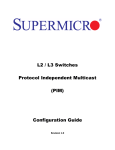
Figure VLAN-1: VLANs on a Switched LAN
Switch
VLAN 20
62.10.0.0 IP Subnet
VLAN 20
VLAN 40
44.23.0.0 IP Subnet
VLANs work in same way as physical LANs. The packets from the end stations of a VLAN are switched
only to other end stations or network devices inside that VLAN. To reach devices in another VLAN, the
packets have to be routed from one VLAN to another. Supermicro L2/L3 switches support such
InterVLAN Routing to route packets across different VLANs. InterVLAN Routing is done by creating
“Layer 3 Interface VLANs”.
This document covers only Layer 2 VLANs. The Layer 3 Interface VLAN feature is explained in
the IP Configuration Guide.
1.2 VLAN Support
Supermicro switches support the three types of VLANs – MAC Based VLANs, Protocol Based VLANs and
Port Based VLANs.
Supermicro L2/L3 Switches Configuration Guide
5
VLAN Configuration Guide
Figure VLAN-2: Types of VLANs Supported
MAC Based
VLAN
Protocol
Based VLAN
Port Based
VLAN
Once a packet is received, a switch tries to identify the VLAN for the received packet. This VLAN
identification is done according to the procedure below.
If the incoming packet has a VLAN tag and the VLAN ID in the tag is not equal to zero, then this VLAN ID
is used as the VLAN for this packet.
If the incoming packet does not have a VLAN tag (untagged packet) or if the VLAN ID in the VALN tag is
equal to zero (priority tagged packet), the packet is considered as untagged/priority tagged and the
below steps are used to identify the VLAN for this untagged/priority tagged packet.
Step 1: Use the source MAC of the incoming packet and check the MAC VLAN mapping. If the VLAN is
found for this source MAC, that VLAN ID is used as the VLAN for this packet. If the MAC VLAN is not
found, proceed to the next step.
Step 2: Use the protocol field from the incoming packet layer 2 header and check the protocol VLAN
table. If a protocol VLAN is found, that VLAN ID is used as the VLAN for this packet. If a protocol VLAN is
not found, proceed to the next step.
Step 3: Use the PVID from the port on which the packet is received as the VLAN ID for this packet.
This VLAN identification procedure is shown in Figure VLAN-3: VLAN Identification Procedure.
Once the VLAN is identified for the received packet, it will be forwarded to any other member port of
this VLAN based on the forwarding logic. If there are no other member ports for this VLAN, the packet
will most likely be dropped unless it was routed or sent to the CPU or redirected by an ACL rule.
Supermicro L2/L3 Switches Configuration Guide
6
VLAN Configuration Guide
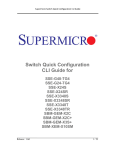
Figure VLAN-3: VLAN Identification Procedure
Packet has
VLAN tag?
No
Yes
VLAN ID
No
Check Src MAC for
MAC VLAN
Found MAC
VLAN ?
!= 0 ?
Yes
Use VLAN ID
from VLAN tag
Yes
Use MAC
VLAN ID
Yes
Use Protocol
VLAN ID
No
Check Protocol VLAN
Found Proto
VLAN ?
No
Use PVID as
VLAN ID
Use PVID
Found VLAN
1.3 VLAN Numbers
Supermicro switches support VLAN identifiers from 1 to 4069 for user created VLANs. VLAN identifiers
4070 to 4094 are reserved for internal use.
The number of supported VLANs differs among different models of Supermicro switch products as
shown in the table below.
Switch Product
Number of VLANS Supported
SSE-G24-TG4
1024
Supermicro L2/L3 Switches Configuration Guide
7
VLAN Configuration Guide
SSE-G48-TG4
SBM-GEM-X2C
SBM-GEM-X2C+
SBM-GEM-X3S+
SSE-X24S
4094
SBM-XEM-X10SM
SSE-X3348S
SSE-X3348T
The command “show vlan device info” displays the maximum VLAN identifiers and total
number of VLANs supported by the switch.
All the above switch models support 1024 MAC based VLANs.
Supermicro switches support 16 protocol groups for protocol based VLANs. These 16 protocol groups
can be mapped to different VLANs in every port. Same protocol group can be associated with different
VLAN in different port.
1.4 VLAN Defaults
Supermicro switches boot up with VLAN 1, which is a default Layer 2 VLAN. The switchable ports of all
switches are added to this default VLAN 1 as access ports. This default setup helps switch forwarding
traffic across all the ports without the need of any user configuration.
Users can modify the port members of this VLAN 1 by adding or removing any ports to this VLAN 1 as
either tagged or untagged ports.
VLAN 1 cannot be deleted by the user. Instead, a user can remove all the ports from VLAN 1
to make it nonfunctional. This can be done by using the “no ports” command in VLAN the
configuration mode in CLI.
The port based VLAN identifier (PVID) for all the switch ports is set to 1 by default. The PVID is used to
associate incoming untagged packets to port based VLANs. Users can modify the PVID for switch ports to
any VLAN identifier.
The switch port mode is set to “hybrid” for all switch ports by default. Users can change the port mode
as explained in the Port Based VLAN Section.
Supermicro L2/L3 Switches Configuration Guide
8
VLAN Configuration Guide
VLAN 1 is configured as the default native VLAN for all trunk interfaces. Users can change the native
VLANs for trunk interfaces as explained in section Native VLAN on Trunk.
Protocol based VLAN is enabled by default.
Supermicro switches do not create VLANs by default except for VLAN 1. Users need to
create all the VLANs used on their network in Supermicro switches. Trunk ports will be able
to carry only VLANs created in Supermicro switches.
1.5 Creating VLANs
Follow the steps below to create VLANs in Supermicro switches.
Step
Command
Description
Step 1
Step 2
configure terminal
vlan <vlan-list>
Enters the configuration mode
Creates a VLAN using vlan command.
vlan-list – may be any vlan number or
list of vlan numbers. Multiple vlan
numbers can be provided as commaseparated values. Consecutive vlan
numbers can be provided as a range,
such as 5-10.
Step 3
Step 4
User can configure VLANs with
identifiers 1 to 4069.
Displays the configured VLANs
Optional step – Save these VLAN
configuration to be part of startup
configuration.
show vlan
write startup-config
The examples below show various ways of creating VLANs.
Create a VLAN with identifier 10
SMIS# configure terminal
SMIS(config)# vlan 10
SMIS(config-vlan)# exit
Create VLANs with identifiers 20 to 30, 50 and 100
SMIS# configure terminal
SMIS(config)# vlan 20-30,50,100
SMIS(config-vlan)# exit
Supermicro L2/L3 Switches Configuration Guide
9
VLAN Configuration Guide
1.6 Modifying VLANs
To modify a configured VLAN, follow the same steps used to create a VLAN as explained in the Creating
VLANs section.
1.7 Removing VLANs
Follow the steps below to remove VLANs from Supermicro switches.
Step
Command
Description
Step 1
Step 2
configure terminal
no vlan <vlan-list>
Enter the configuration mode
Remove VLANs using the no vlan
command.
Step 3
Step 4
vlan-list – may be any vlan number or
list of vlan numbers. Multiple vlan
numbers can be provided as comma
separated list. Consecutive vlan
numbers can be provided as ranges like
5-10.
To display the configured VLANs
Optional step – Save these VLAN
configuration to be part of startup
configuration.
show vlan
write startup-config
The below examples show sample ways to remove VLANs.
Delete a VLAN with identifier 10
SMIS# configure terminal
SMIS(config)# no vlan 10
Delete VLANs with identifier 20 to 30, 50 and 100
SMIS# configure terminal
SMIS(config)# no vlan 20-30,50,100
SMIS(config-vlan)# exit
1.8 VLAN Name
VLANs can be associated with a label name string for easier configuration and identification.
Follow the steps below to add or modify a name string to any VLAN in Supermicro switches.
Supermicro L2/L3 Switches Configuration Guide
10
VLAN Configuration Guide
Step
Command
Description
Step 1
Step 2
configure terminal
vlan <vlan-list>
Enters the configuration mode.
Enters the VLAN configuration mode.
vlan-list – may be any VLAN number or
list of VLAN numbers. Multiple VLAN
numbers can be provided as commaseparated values. Consecutive VLAN
numbers can be provided as a range,
such as 5-10.
Step 3
Step 4
Step 5
name <vlan-name-string>
show vlan
write startup-config
If multiple VLANs are provided, the
same name string provided in next step
will be associated with all these VLANs.
Associates a name string to this VLAN
using the name command.
vlan-name-string is any alphanumeric
string up to 32 characters.
Displays the configured VLANs
Optional step – saves this VLAN
configuration to be part of startup
configuration.
The example below shows the necessary steps to associate a name string to a VLAN.
Associate name main_user_vlan to VLAN 50.
SMIS# configure terminal
SMIS(config)# vlan 50
SMIS(config-vlan)# name main_user_vlan
SMIS(config-vlan)# exit
Follow the steps below to remove a name string from any VLAN in Supermicro switches.
Step
Command
Description
Step 1
Step 2
configure terminal
vlan <vlan-list>
Enters the configuration mode.
Enters the VLAN configuration mode.
vlan-list – may be any VLAN number or
list of VLAN numbers. Multiple VLAN
numbers can be provided as commaseparated values. Consecutive VLAN
numbers can be provided as a range,
such as 5-10.
Supermicro L2/L3 Switches Configuration Guide
11
VLAN Configuration Guide
Step 3
no name
Step 4
Step 5
show vlan
write startup-config
If multiple VLANs are provided, the
name string of all these VLANs will be
removed by the next step.
Removes associated name string from
this VLAN.
Displays the configured VLANs
Optional step – saves this VLAN
configuration to be part of startup
configuration.
The example below shows steps to remove name string from a VLAN.
Remove name from VLAN 50.
SMIS# configure terminal
SMIS(config)# vlan 50
SMIS(config-vlan)# no name
SMIS(config-vlan)# exit
1.9 Port Based VLANs
Port based VLANs are the simplest and most useful type of VLAN.
In port based VLAN deployment, switch ports are associated with one or more VLANs as member ports.
The VLAN traffic sent on the ports is decided by the VLAN membership modes of the ports. Mostly ports
are associated with VLANs as either “access” port members or “trunk” port members. Supermicro
switches support an additional port mode called “hybrid”.
Port Channel interfaces also can be configured as VLAN member ports.
Supermicro L2/L3 Switches Configuration Guide
12
VLAN Configuration Guide
Figure VLAN-4: Port Based VLANs
Trunk Links
Access Links
VLAN 20 & 30
Switch A
Switch B
VLAN 20 & 30
VLAN 20 & 30
VLAN 40
1.9.1 Access Ports
Access ports carry traffic of only one VLAN. Any switch ports can be configured as access ports. Mostly
switch ports connected to end stations (computers / servers) that have only one type of traffic are
configured as access ports.
Access ports cannot be configured to be part of more than one VLAN.
When a switch port is configured as an access port to any VLAN, that port is added as an untagged
member port of the given VLAN. Also, the Port based VLAN identifier (PVID) of that port is configured as
the given VLAN.
Switch strips the VLAN tag header from all packets sent out on an access port. Hence, access ports are
also called untagged ports.
When a packet is received on an access port, the switch identifies the VLAN for the received packet from
the packet’s VLAN tag header. If the received packet did not have a VLAN identifier and the packet did
not match any MAC or protocol VLAN, the port PVID is used as VLAN for all the received untagged and
priority tagged packets.
Follow the below steps to configure any port as the access port of any VLAN.
Step
Command
Description
Step 1
Step 2
configure terminal
Enters the configuration mode
interface <interface-type> <interface-id>
Enters the interface mode.
or
interface range <interface-type> <interface-id> interface-type – may be any of the
Supermicro L2/L3 Switches Configuration Guide
13
VLAN Configuration Guide
….
following:
gigabitethernet – gi
extreme-ethernet – ex
qx-ethernet – qx
port-channel – po
interface-id is in slot/port format for all
physical interfaces. It may be the port
channel identifier for port channel
interfaces.
Step 3
Step 4
To configure multiple interfaces, use
the “interface range …” command. To
provide a range use a hypen (-)
between the start and end interface
numbers.
E.g.: int range gi 0/1-10
To provide multiple interfaces or
ranges, use separate with a comma (,).
E.g.: int range gi 0/1-10, gi 0/20
Sets the port mode as the access port.
Configures the access VLAN for this
interface. The VLANs identifiers may be
any VLAN number from 1 to 4069.
switchport mode access
switchport access vlan <vlan-id>
Step 5
show vlan port config port <iftype> <ifnum>
Step 6
write startup-config
The VLAN provided in this command
must exist in the switch. If the VLAN
does not exist, create it first.
Displays the configured mode and
accesses the VLAN for this interface.
Optional step – saves this VLAN
configuration to be part of startup
configuration.
“no switchport mode” command will change the port mode to the default hybrid mode. For
more details about hybrid mode, refer to section Hybrid Ports.
“no switchport access vlan” command will set the access VLAN as default VLAN 1. The port
will continue to be the access port of VLAN 1.
The examples below show various ways to create VLANs with access ports.
Create a VLAN with identifier 50 and configure ports gi 0/2 to gi 0/10 as access ports to this VLAN.
SMIS# configure terminal
Supermicro L2/L3 Switches Configuration Guide
14
VLAN Configuration Guide
SMIS(config)# vlan 50
SMIS(config-vlan)# exit
SMIS(config)# interface range gi 0/2-10
SMIS(config-if)# switchport mode access
SMIS(config-if)# switchport access vlan 50
SMIS(config-if)# exit
Create a VLAN with identifier 10 and configure port channel 1 as access port to this VLAN.
SMIS# configure terminal
SMIS(config)# vlan 10
SMIS(config-vlan)# exit
SMIS(config)# interface po 1
SMIS(config-if)# switchport mode access
SMIS(config-if)# switchport access vlan 10
SMIS(config-if)# exit
1.9.2 Trunk Ports
Trunk ports carry the traffic of one or more VLANs. Any switch ports can be configured as trunk ports.
Mostly switch ports connected between switches are configured as trunk ports to carry multiple VLAN
traffic across switches. Switch ports connected to end stations (computers / servers) that have multiple
VLANs are also configured as trunk ports.
When a switch port is configured as trunk port, by default it will be added to all the VLANs in the switch
as a tagged port. To restrict the VLANs carried in trunk ports, refer section Allowed VLANs on a Trunk.
Trunk ports will not carry traffic for VLANs that are not configured in a switch.
For example, if the user wants to carry traffic for all the VLANs from 1 to 1024 in a trunk
port, VLANs 1 to 1024 need to be created in the switch using the “vlan” command.
A switch adds the VLAN tag header to all packets sent out on the trunk port except for native VLAN
traffic. Supermicro switches support only IEEE 802.1Q encapsulation for VLAN tag headers.
When a packet is received on a trunk port, the switch identifies the VLAN for the received packet from
the packet’s VLAN tag header. If the received packet did not have a VLAN identifier and the packet did
not match any MAC or protocol VLAN, the port PVID is used to determine the VLAN for all untagged and
priority tagged packets that are received.
A native VLAN identifier is configured as a PVID for the trunk ports. If the user has not configured a
native VLAN, the default VLAN 1 will be used as PVID for the trunk ports.
Follow the steps below to configure any port as a trunk port.
Step
Command
Description
Step 1
configure terminal
Enters the configuration mode
Supermicro L2/L3 Switches Configuration Guide
15
VLAN Configuration Guide
Step 2
interface <interface-type> <interface-id>
Enters the interface mode.
or
interface range <interface-type> <interface-id> interface-type – may be any of the
following:
….
gigabitethernet – gi
extreme-ethernet – ex
qx-ethernet – qx
port-channel – po
interface-id is in slot/port format for all
physical interfaces. It may be a port
channel identifier for port channel
interfaces.
Step 3
Step 4
Step 5
switchport mode trunk
show vlan port config port <iftype> <ifnum>
and
show running-config
write startup-config
To configure multiple interfaces, use
the “interface range …” command. To
provide a range, use a hypen (-)
between the start and end interface
numbers.
E.g.: int range gi 0/1-10
To provide multiple interfaces or
ranges, separate with a comma (,).
E.g.: int range gi 0/1-10, gi 0/20
Sets the port mode as a trunk port.
Displays the configured mode for this
interface.
Optional step – saves this VLAN
configuration to be part of startup
configuration.
“no switchport mode” command will change the port mode to the default hybrid mode. For
more details about hybrid mode, refer to the Hybrid Ports section.
The examples below show various ways to configure trunk ports.
Configure port ex 0/1 and ex 0/2 as trunk ports.
SMIS# configure terminal
SMIS(config)# interface range ex 0/1-2
SMIS(config-if)# switchport mode trunk
SMIS(config-if)# exit
Configure port channel 1 as a trunk port.
Supermicro L2/L3 Switches Configuration Guide
16
VLAN Configuration Guide
SMIS# configure terminal
SMIS(config)# interface po 1
SMIS(config-if)# switchport mode trunk
SMIS(config-if)# exit
1.9.2.1 Allowed VLANs on a Trunk
By default, all the VLANs configured on a switch are allowed on the trunk interfaces. However, there
may be some cases where users would like to limit the number of VLANs carried on the trunk ports. This
can be configured by following the steps below.
Step
Command
Description
Step 1
Step 2
configure terminal
interface <interface-type> <interface-id>
or
interface range <interface-type> <interface-id>
….
Enters the configuration mode
Enters the interface mode.
interface-type – may be any of the
following:
gigabitethernet – gi
extreme-ethernet – ex
qx-ethernet – qx
port-channel – po
interface-id is in slot/port format for all
physical interfaces. It may be a port
channel identifier for port channel
interfaces.
Step 3
Step 4
Step 4a
To configure multiple interfaces, use
the “interface range …” command. To
provide a range, use a hypen (-)
between the start and end interface
numbers.
E.g.: int range gi 0/1-10
To provide multiple interfaces or
ranges, separate with a comma (,).
E.g.: int range gi 0/1-10, gi 0/20
switchport mode trunk
Sets the port mode as trunk port.
Use any one of the below steps 4a to 4f based on The vlan-list parameter used in the
the need.
below commands could be any VLAN
number or list of VLAN numbers.
Multiple VLAN numbers can be
provided as comma-separated values.
Consecutive VLAN numbers can be
provided as a range, such as 5-10.
switchport trunk allowed vlan <vlan-list>
This command configures the list of
allowed VLANs on this trunk. Only the
VLANs provided on the vlan-list will be
Supermicro L2/L3 Switches Configuration Guide
17
VLAN Configuration Guide
Step 4b switchport trunk allowed vlan add <vlan-list>
Step 4c
switchport trunk allowed vlan remove <vlan-list>
Step 4d switchport trunk allowed vlan except <vlan-list>
Step 4e
switchport trunk allowed vlan all
Step 4f
switchport trunk allowed vlan none
Step 5
show vlan port config port <iftype> <ifnum>
and
show running-config
write startup-config
Step 6
carried over the trunk.
This command adds the given list of
VLANS to the existing set of allowed
VLANs on this trunk.
This command removes the given list of
VLANS from the existing set of allowed
VLANs on this trunk.
This command makes all the configured
VLANs allowed on this trunk except for
the given list of VLANs.
This command sets the default
behavior of allowing all VLANs
configured in the switch as allowed
VLANs on this trunk.
This command removes all the allowed
VLANs from this trunk.
Displays the configured, allowed VLANs
for this trunk interface.
Optional step – saves this VLAN
configuration to be part of startup
configuration.
A trunk port will not carry traffic for any VLANs that are not configured in the switch.
For example, if a user wants to allow traffic for VLANs 1 to 100, VLANs 1 to 100 need to be
created in the switch using the “vlan” command.
The examples below show examples of configurations to allow VLANs on trunk ports.
Configure to allow only VLANs 2 to 20 on trunk interface ex 0/1.
SMIS# configure terminal
SMIS(config)# vlan 2-20
SMIS(config-vlan)# exit
SMIS(config)# interface ex 0/1
SMIS(config-if)# switchport mode trunk
SMIS(config-if)# switchport trunk allowed vlan 2-20
SMIS(config-if)# exit
Configure to not to allow VLANs 30 to 50 on trunk interface ex 0/1.
SMIS# configure terminal
SMIS(config)# interface ex 0/1
SMIS(config-if)# switchport mode trunk
Supermicro L2/L3 Switches Configuration Guide
18
VLAN Configuration Guide
SMIS(config-if)# switchport trunk allowed vlan except 30-50
SMIS(config-if)# exit
1.9.2.2 Native VLAN on Trunk
All packets sent out on a trunk interface carry the 802.1Q VLAN tag header. There may be cases in which
untagged packets need to be carried over a trunk interface. This is achieved by using the native VLAN
feature of the trunk interface.
Any VLAN can be configured on any trunk interface as a native VLAN. Trunk interfaces will send native
VLAN packets as untagged packets without adding the 802.1Q VLAN tag header. Similarly, any untagged
packets received on a trunk interface will be considered to be native VLAN packets.
The native VLAN identifier will be configured as a PVID on trunk interfaces. VLAN 1 is the default native
VLAN for all trunk interfaces.
Figure VLAN-5: Native VLANs
Trunk Links
Access Links
Native VLAN 40
VLAN
40
Switch A
Switch B
VLAN
20 & 30
VLAN 20 & 30
VLAN 40
Users can configure a native VLAN for trunk interfaces by following the steps below.
Step
Command
Description
Step 1
Step 2
configure terminal
interface <interface-type> <interface-id>
or
interface range <interface-type> <interface-id>
….
Enters the configuration mode
Enters the interface mode.
interface-type – may be any of the
following:
gigabitethernet – gi
extreme-ethernet – ex
qx-ethernet – qx
Supermicro L2/L3 Switches Configuration Guide
19
VLAN Configuration Guide
port-channel – po
interface-id is in slot/port format for all
physical interfaces. It may be a port
channel identifier for port channel
interfaces.
Step 3
Step 4
Step 5
Step 6
switchport mode trunk
switchport trunk native vlan <vlan-id >
show vlan port config port <iftype> <ifnum>
and
show running-config
write startup-config
To configure multiple interfaces, use
the “interface range …” command. To
provide a range, use a hypen (-)
between the start and end interface
numbers.
E.g.: int range gi 0/1-10
To provide multiple interfaces or
ranges, separate with a comma (,).
E.g.: int range gi 0/1-10, gi 0/20
Sets the port mode as a trunk port.
vlan-id - The VLAN identifiers may be
from 1 to 4069.
The VLAN provided in this command
must exist in the switch. If the VLAN
does not exist, create it first.
Displays the configured native VLAN for
this trunk interface.
Optional step – saves this VLAN
configuration to be part of startup
configuration.
“no switchport trunk native vlan” command will reset the native VLAN as VLAN 1 for trunk
interfaces.
The examples below show examples of configuring native VLANs for trunk ports.
Configure VLAN 20 as a native VLAN for trunk interface ex 0/1.
SMIS# configure terminal
SMIS(config)# vlan 20
SMIS(config-vlan)# exit
SMIS(config)# interface ex 0/1
SMIS(config-if)# switchport mode trunk
SMIS(config-if)# switchport trunk native vlan 20
SMIS(config-if)# exit
Supermicro L2/L3 Switches Configuration Guide
20
VLAN Configuration Guide
Remove a native VLAN from trunk interface ex 0/1.
SMIS# configure terminal
SMIS(config)# interface ex 0/1
SMIS(config-if)# no switchport trunk native vlan
SMIS(config-if)# exit
1.9.3 Hybrid Ports
Hybrid ports carry both untagged and 802.1Q tagged packets. Hybrid ports are equivalent to trunk ports,
with a limited amount of allowed VLANs and native VLANs.
Hybrid ports carry the traffic of one or more VLANs. Any switch port can be configured as a hybrid port.
In Supermicro switches, all switch ports by default come up in hybrid mode.
Users need to explicitly add the hybrid ports to all the required VLANs as either tagged or untagged
interfaces. A hybrid port could be configured simultaneously as a tagged port on one or more VLANs and
as an untagged port on any one VLAN. Similar to access ports, hybrid ports may be an untagged port on
only one VLAN, but may be a tagged port on many VLANs.
Users need to configure the PVID for hybrid ports to correctly handle the incoming untagged packets.
It is recommended for users to use hybrid ports only when they thoroughly understand the
PVID, tagged and untagged interfaces of their network.
Hybrid ports might cause VLAN packet forwarding drops if the ports are not correctly added
to the required VLANs as untagged or tagged interfaces as needed.
Hybrid ports can be configured through trunk ports with allowed VLANs and a native VLAN
configuration.
A switch adds the 802.1Q VLAN tag header for VLAN traffic in which the hybrid port is configured as a
tagged interface. The switch sends out packets without a VLAN tag header for the VLAN on which the
hybrid port is configured as an untagged interface.
When a packet is received on a hybrid port, a switch identifies the VLAN for the received packet from
the packet’s VLAN tag header. If the received packet did not have a VLAN identifier and the packet did
not match any MAC or protocol VLAN, the port PVID is used as the VLAN for all the received untagged
and priority tagged packets. If the user has not configured the PVID, VLAN 1 will be used as the default
PVID for hybrid ports.
Follow the steps below to configure any port as a hybrid port.
Step
Command
Description
Step 1
configure terminal
Enters the configuration mode
Supermicro L2/L3 Switches Configuration Guide
21
VLAN Configuration Guide
Step 2
vlan <vlan-list>
vlan-list – may be any VLAN number or
list of VLAN numbers. Multiple VLAN
numbers can be provided as commaseparated values. Consecutive VLAN
numbers can be provided as a range,
such as 5-10.
If multiple VLANs are provided, the
ports configuration provided in the next
steps will be applied to all these VLANs.
Step 3
Step 3a
Use steps 3a to 3c below one or more times to
configure the required port configurations for the
VLANs provided in Step 2 above.
ports <ports-list> tagged
Adds the tagged ports list to this VLAN.
or
no ports [<ports-list>] tagged
ports-list – up to three ports or three
ranges of ports separated by spaces.
The range of ports is provided in the
format gi 0/1-10, which specifies the
ports from gi 0/1 to gi 0/10.
Step 3b ports <ports-list> untagged
or
no ports [<ports-list>] untagged
Use the no form of this command to
remove tagged ports from this VLAN.
If ports-list is not provided to the no
command, all the tagged ports are
removed from this VLAN.
Adds the untagged ports list to this
VLAN.
ports-list – up to three ports or three
ranges of ports separated by spaces.
The range of ports is provided in the
format gi 0/1-10, which specifies the
ports from gi 0/1 to gi 0/10.
Step 3c
ports <ports-list> forbidden
or
no ports [<ports-list>] forbidden
Use the no form of this command to
remove untagged ports from this VLAN.
If ports-list is not provided to the no
command, all the untagged ports are
removed from this VLAN.
Denies traffic from ports given by
ports-list to this VLAN.
ports-list – up to three ports or ranges
of ports separated by spaces.
The range of ports is provided in the
format gi 0/1-10, which specifies the
ports from gi 0/1 to gi 0/10.
Supermicro L2/L3 Switches Configuration Guide
22
VLAN Configuration Guide
Step 4
Step 5
Use the no form of this command to
remove forbidden ports from this
VLAN.
If ports-list is not provided to the no
command, all the forbidden ports are
removed from this VLAN.
Exits the VLAN configuration mode.
Enters the interface mode.
exit
interface <interface-type> <interface-id>
or
interface range <interface-type> <interface-id> interface-type – may be any of the
following:
….
gigabitethernet – gi
extreme-ethernet – ex
qx-ethernet – qx
port-channel – po
interface-id is in slot/port format for all
physical interfaces. It may be a port
channel identifier for port channel
interfaces.
Step 6
Step 7
Step 8
To configure multiple interfaces, use
the “interface range …” command. To
provide a range, use a hypen (-)
between the start and end interface
numbers.
E.g.: int range gi 0/1-10
To provide multiple interfaces or
ranges, separate with a comma (,).
E.g.: int range gi 0/1-10, gi 0/20
Sets the port mode as a hybrid port.
Configures the PVID for this interface.
The VLANs identifiers could be any
VLAN number from 1 to 4069.
switchport mode hybrid
switchport pvid <vlan-id>
show vlan port config port <iftype> <ifnum>
The VLAN provided in this command
must exist in the switch. If the VLAN
does not exist, create it first.
Displays the configured VLAN and ports
information.
show running-config
Step 9
show vlan
write startup-config
Optional step – saves this VLAN
configuration to be part of startup
configuration.
Supermicro L2/L3 Switches Configuration Guide
23
VLAN Configuration Guide
Any port may be configured as an untagged port into only one VLAN.
Untagged ports should be either in hybrid or access mode. Ports in trunk mode cannot be
configured as untagged ports.
The examples below show various ways to configure hybrid ports.
Configure a VLAN 10 with ports gi 0/1 to gi 0/10 as untagged ports and add port ex 0/1 as a tagged
port to this VLAN.
SMIS# configure terminal
SMIS(config)# vlan 10
SMIS(config-vlan)# ports gi 0/1-10 untagged
SMIS(config-vlan)# ports ex 0/1 tagged
SMIS(config-vlan)# exit
SMIS(config)# interface range gi 0/1-10
SMIS(config-if)# switchport mode hybrid
SMIS(config-if)# switchport pvid 10
SMIS(config-if)# exit
Configure a VLAN 100 with ports gi 0/1, gi 0/10, gi 0/20, gi 0/30, gi 0/40 and ex 0/1-2 as untagged
ports and add port channel 1 as a tagged port to this VLAN.
SMIS# configure terminal
SMIS(config)# vlan 100
SMIS(config-vlan)# ports gi 0/1 gi 0/10 gi 0/20 untagged
SMIS(config-vlan)# ports gi 0/30 gi 0/40 ex 0/1-2 untagged
SMIS(config-vlan)# ports po 1 tagged
SMIS(config-vlan)# exit
SMIS(config)# interface range gi 0/1,gi 0/10, gi 0/20, gi 0/30, gi 0/40, ex 0/1-2
SMIS(config-if)# switchport mode hybrid
SMIS(config-if)# switchport pvid 100
SMIS(config-if)# exit
1.9.4 Acceptable Frame Types
By default, Supermicro switch ports accept all frames types – tagged, untagged and priority tagged.
Priority tagged packets have a VLAN tag header with a VLAN identifier of 0.
Users can control this behavior to make switch ports accept either only tagged or untagged and priority
tagged packets.
Supermicro L2/L3 Switches Configuration Guide
24
VLAN Configuration Guide
Follow the steps below to configure acceptable frame types for any port or port channel.
Step
Command
Description
Step 1
Step 2
configure terminal
interface <interface-type> <interface-id>
or
interface range <interface-type> <interface-id>
….
Enters the configuration mode
Enters the interface mode.
interface-type – may be any of the
following:
gigabitethernet – gi
extreme-ethernet – ex
qx-ethernet – qx
port-channel – po
interface-id is in slot/port format for all
physical interfaces. It may be a port
channel identifier for port channel
interfaces.
To configure multiple interfaces, use
the “interface range …” command. To
provide a range, use a hypen (-)
between the start and end interface
numbers.
E.g. : int range gi 0/1-10
To provide multiple interfaces or
ranges, separate with a comma (,).
E.g. : int range gi 0/1-10, gi 0/20
Step 3
Use any of the below steps 3a to 3d to configure
acceptable frame types for the ports provided in
Step 2 above.
Step 3a
switchport acceptable-frame-type tagged
Step 3b switchport acceptable-frame-type
untaggedAndPrioritytagged
Step 3c
switchport acceptable-frame-type all
Step 3d no switchport acceptable-frame-type
This command makes only tagged
frame types accepted on these ports.
Any untagged or priority tagged packets
received will be dropped.
This command makes only untagged
and priority tagged frame types
accepted on these ports.
Any tagged packets received will be
dropped.
This command makes accepting all
frame types the default behavior.
This command makes accepting all
frame types the default behavior.
Supermicro L2/L3 Switches Configuration Guide
25
VLAN Configuration Guide
Step 5
show vlan port config port <iftype> <ifnum>
Step 6
write startup-config
Displays the configured mode and
access VLAN for this interface.
Optional step – saves this VLAN
configuration to be part of startup
configuration.
The examples below show various ways to configure acceptable frame types on switch ports.
Configure gi 0/1 to gi 0/10 to accept only untagged and priority tagged packets.
SMIS# configure terminal
SMIS(config)# interface range gi 0/1-10
SMIS(config-if)# switchport acceptable-frame-type untaggedAndPrioritytagged
SMIS(config-if)# exit
Configure port channel interface 1 to accept only tagged packets.
SMIS# configure terminal
SMIS(config)# interface po 1
SMIS(config-if)# switchport acceptable-frame-type tagged
SMIS(config-if)# exit
1.10
MAC Based VLANs
When end users move often from one place to another but remain inside the same LAN, it is difficult to
maintain the same VLAN for an end user with port based VLAN configurations.
MAC based VLAN features are used to provide the same VLAN to any end user irrespective of the switch
port the end user connecting to.
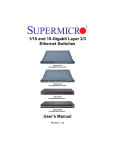
The switch administrator could configure MAC to VLAN mappings for unicast MAC addresses. When a
switch receives any untagged packets, the source MAC address of the packet refers to this MAC VLAN
mapping to identify the VLAN. If MAC VLAN mapping is not found for the received source MAC address,
a protocol based VLAN or port based VLAN is used.
Supermicro switches support 1024 MAC based VLANs.
Supermicro L2/L3 Switches Configuration Guide
26
VLAN Configuration Guide
Figure VLAN-6: MAC Based VLANs
MAC Address
00:30:48:0a:dd:e3
00:30:48:04:02:89
00:30:48:01:72:58
00:30:48:d8:ed:54
VLAN
10
20
20
30
Switch
00:30:48:0a:dd:e3
VLAN 10
00:30:48:04:02:89
VLAN 20
00:30:48:01:72:58
VLAN 20
00:30:48:d8:ed:54
VLAN 30
Follow the steps below to configure MAC based VLANs.
Step
Command
Description
Step 1
Step 2
configure terminal
vlan <vlan-list>
Enters the configuration mode
Creates the required VLANs.
exit
mac-vlan <ucast_mac> vlan <vlan-id>
vlan-list – may be any VLAN number or
list of VLAN numbers. Multiple VLAN
numbers can be provided as comma
separated values. Consecutive VLAN
numbers can be provided as ranges
such as 5-10.
Exits the VLAN configuration mode.
Configures MAC VLAN mapping entry.
Step 3
Step 4
ucast_mac – Unicast MAC address.
This VLAN will be applied to all
incoming untagged packets from this
unicast MAC address.
Step 5
show mac-vlan
Step 5
write startup-config
vlan-id - VLAN identifiers may be any
VLAN number from 1 to 4069. The
VLAN must have already been created
in this switch.
Displays the configured MAC based
VLANs.
Optional step – saves this VLAN
configuration to be part of startup
configuration.
Supermicro L2/L3 Switches Configuration Guide
27
VLAN Configuration Guide
User has to create the VLANs using the “vlan ..” command prior to configuring MAC address
VLAN mapping.
Follow the steps below to remove MAC based VLANs.
Step
Command
Description
Step 1
Step 2
configure terminal
no mac-vlan <ucast_mac>
Enters the configuration mode
Removes MAC VLAN mapping entry.
Step 3
show mac-vlan
Step 4
write startup-config
ucast_mac – Unicast MAC address for
which MAC VLAN mapping is to be
removed.
Displays the configured MAC based
VLANs.
Optional step – saves this VLAN
configuration to be part of startup
configuration.
The examples below show various ways to configure MAC based VLANs.
Create a VLAN 10 and configure MAC address 00:30:40:10:10:10 to VLAN 10.
SMIS# configure terminal
SMIS(config)# vlan 10
SMIS(config-vlan)# exit
SMIS(config)# mac-vlan 00:30:40:10:10:10 vlan 10
Remove MAC VLAN for MAC address 00:30:40:20:20:20.
SMIS# configure terminal
SMIS(config)# no mac-vlan 00:30:40:20:20:20
1.11
Protocol Based VLANs
Protocol Based VLAN features help to classify incoming traffic to different VLANs based on protocol. The
protocol or ethertype field in the Layer 2 header is used to classify the packets to different VLANs.
Protocol VLAN features are enabled by default in Supermicro switches.
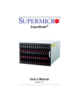
Protocol based VLAN features configuration is a three-step process, as shown in the diagram below.
Supermicro L2/L3 Switches Configuration Guide
28
VLAN Configuration Guide
Figure VLAN-7: Protocol Based VLAN Configuration Steps
1. Create VLANs and add ports
2. Create protocol groups
3. Associate groups to VLANs in ports
Follow the steps below to configure protocol based VLANs.
Step
Command
Description
Step 1
Step 2
configure terminal
vlan <vlan-list>
Step 3
ports <ports-list> untagged
Enters the configuration mode
vlan-list – may be any VLAN number or
list of VLAN numbers. Multiple VLAN
numbers can be provided as comma
separated values. Consecutive VLAN
numbers can be provided as a range,
such as 5-10.
Adds the required ports for this VLAN
as untagged ports.
Step 4
Step 5
ports-list – up to three ports or three
ranges of ports separated by spaces.
The range of ports is provided in a
format like gi 0/1-10, which refers to
ports from gi 0/1 to gi 0/10.
exit
Exits the VLAN configuration mode.
map protocol {arp | ip | rarp | ipx | novell | Creates a protocol group.
netbios | appletalk | other <aa:aa or
aa:aa:aa:aa:aa>} {enet-v2 | RFC1042 | llcOther Protocol group creation takes three
| snap8021H | snapOther} protocols-group parameters.
<Group id integer(0-2147483647)>
First: protocol field as arp, ip, rarp,
ipx,novell, netbios or appletalk.
Users can enter any other two-byte
protocol fields in hex format as aa:aa.
Second: frame type as enet-v2, llc or
snap.
Step 6
interface <interface-type> <interface-id>
Third: protocol group
number.
Enters the interface mode.
Supermicro L2/L3 Switches Configuration Guide
identifier
29
VLAN Configuration Guide
or
interface range <interface-type> <interface-id> interface-type – may be any of the
….
following:
gigabitethernet – gi
extreme-ethernet – ex
qx-ethernet – qx
port-channel – po
interface-id is in slot/port format for all
physical interfaces. It could be the port
channel identifier for port channel
interfaces.
Step 7
switchport map protocols-group
integer(0-2147483647)>
vlan
4069)>
Step 8
switchport pvid <vlan-id>
To configure multiple interfaces, use
the “interface range …” command. To
provide a range, use a hypen (-)
between the start and end interface
numbers.
E.g.: int range gi 0/1-10
To provide multiple interfaces or
ranges, separate with a comma (,).
E.g.: int range gi 0/1-10, gi 0/20
<Group id Associates the group to the VLAN on
<vlan-id(1- the above interface.
Group id – Protocol Group Identifier
vlan-id – VLAN identifier.
Configures the PVID for the default port
based VLAN behavior. This will be used
for packets that did not match any
protocol VLAN map.
The VLAN identifiers may be any VLAN
number from 1 to 4069.
Step 9
Step 10
Exit
show vlan protocols-group
Step 11
show protocol-vlan
write startup-config
The VLAN provided in this command
must exist in the switch. If the VLAN
does not exist, create it first.
Exits the interface configuration mode.
Displays the configured protocol based
VLANs.
Optional step – saves this VLAN
configuration to be part of startup
configuration.
Supermicro L2/L3 Switches Configuration Guide
30
VLAN Configuration Guide
Follow the below steps to remove protocol based VLANs.
Step
Command
Description
Step 1
Step 2
configure terminal
interface <interface-type> <interface-id>
or
interface range <interface-type> <interface-id>
….
Enters the configuration mode
Enters the interface mode.
interface-type – may be any of the
following:
gigabitethernet – gi
extreme-ethernet – ex
qx-ethernet – qx
port-channel – po
interface-id is in slot/port format for all
physical interfaces. It could be a port
channel identifier for port channel
interfaces.
Step 3
Step 4
Step 5
Step 6
To configure multiple interfaces, use
the “interface range …” command. To
provide a range, use a hypen (-)
between the start and end interface
numbers.
E.g.: int range gi 0/1-10
To provide multiple interfaces or
ranges, separate with a comma (,).
E.g.: int range gi 0/1-10, gi 0/20
no switchport map protocols-group <Group id Removes the protocol groups from
interface mode.
integer(0-2147483647)>
exit
no map protocol {arp | ip | rarp | ipx | novell |
netbios | appletalk | other <aa:aa or
aa:aa:aa:aa:aa>} {enet-v2 | RFC1042 | llcOther
| snap8021H | snapOther}
no vlan <vlan-list>
Group id – Protocol Group Identifier
Exits VLAN configuration mode.
Removes the protocol group.
Before removing any protocol group, it
must have been removed from all
interfaces.
Removes the VLANs created for
protocol based VLANs.
or
vlan <vlan-list>
no ports <ports-list> untagged
If the VLAN is shared with a MAC or
port based VLAN, then remove only the
ports added during the protocol based
VLAN configuration. To remove the
ports use the “no ports” command in
the VLAN configuration mode.
Supermicro L2/L3 Switches Configuration Guide
31
VLAN Configuration Guide
Step 7
show vlan protocols-group
Step 8
show protocol-vlan
write startup-config
vlan-list – may be any VLAN number or
list of VLAN numbers. Multiple VLAN
numbers can be provided as comma
separated values. Consecutive VLAN
numbers may be provided as a range,
such as 5-10.
Displays the protocol based VLANs.
Optional step – saves this VLAN
configuration to be part of startup
configuration.
The examples below show various ways to configure protocol based VLANs.
Assign all IP traffic to VLAN 20 and all other traffic to VLAN 30 on ports gi 0/1 to gi 0/10.
SMIS# configure terminal
SMIS(config)# vlan 20,30
SMIS(config-vlan)# po gi 0/1-10 untagged
SMIS(config-vlan)# exit
SMIS(config)# map protocol arp enet-v2 protocols-group 1
SMIS(config)# map protocol ip enet-v2 protocols-group 2
SMIS(config)# int range gi 0/1-10
SMIS(config-if)# switchport map protocols-group 1 vlan 20
SMIS(config-if)# switchport map protocols-group 2 vlan 20
SMIS(config-if)# switchport pvid 30
SMIS(config-if)# exit
Remove protocol VLAN 20.
SMIS# configure terminal
SMIS(config)# int range gi 0/1-10
SMIS(config-if)# no switchport map protocols-group 1
SMIS(config-if)# no switchport map protocols-group 2
SMIS(config-if)# exit
SMIS(config)# no map protocol arp enet-v2
SMIS(config)#no map protocol ip enet-v2
SMIS(config)# no vlan 20
1.12
VLAN Configuration Example
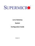
Configure the following requirements on Switch A, as shown below in Figure VLAN-8.
Supermicro L2/L3 Switches Configuration Guide
32
VLAN Configuration Guide
1. Ports gi 0/1 to gi 0/10 are connected to servers that have VLANs 10, 20 and 30. Here, VLAN 10 is
untagged.
2. Port ex 0/1 is connected to storage, which carries VLAN 20 and 30.
3. Ports gi 0/20 to gi 0/40 are access ports for VLAN 10.
4. Ports ex 0/3 and ex 0/4 are part of a trunk port channel that carries all the VLANs to other
switches with native VLAN 10.
Figure VLAN-8: VLAN Configuration Example
Switch A
Gi 0/20
Ex 0/3
Ex 0/4
Gi 0/40
Gi 0/10
Gi 0/1
Ex 0/1
Switch B
Trunk – po 1
Native VLAN 10
VLAN
10
VLAN
20 & 30
Access Links
VLAN 10, 20 & 30
Trunk Links
SMIS# configure terminal
# Create all the VLANs first
SMIS(config)# vlan 10,20,30
SMIS(config-vlan)# exit
# Configure VLANs for ports gi 0/1-10
SMIS(config)# interface range gi 0/1-10
SMIS(config-if)# switchport mode trunk
SMIS(config-if)# switchport trunk native vlan 10
SMIS(config-if)# exit
# Configure VLANs for port ex 0/1
SMIS(config)# int ex 0/1
SMIS(config-if)# switchport mode trunk
SMIS(config-if)# exit
Supermicro L2/L3 Switches Configuration Guide
33
VLAN Configuration Guide
# Configure the access VLAN for ports gi 0/20 to gi 0/40
SMIS(config)# interface range gi 0/20-40
SMIS(config-if)# switchport mode access
SMIS(config-if)# switchport access vlan 10
SMIS(config-if)# exit
# Configure the port channel trunk interface on ex 0/3 and ex 0/4
SMIS(config)# interface port-channel 1
SMIS(config-if)# exit
SMIS(config)# interface range ex 0/3-4
SMIS(config-if)# channel-group 1 mode on
SMIS(config-if)# exit
SMIS(config)# interface port-channel 1
SMIS(config-if)# switchport mode trunk
SMIS(config-if)# switchport trunk native vlan 10
SMIS(config-if)# end
# Check the running-configuration for accuracy
SMIS# show running-config
Building configuration...
Switch ID
Hardware Version
Firmware Version
0
SSE-G48-TG4 (P2-01)
1.0.13-7
ip address dhcp
interface port-channel 1
exit
vlan 1
ports gi 0/11-19 untagged
ports gi 0/41-48 untagged
ports ex 0/2 untagged
exit
vlan 10
ports gi 0/1-10 untagged
ports gi 0/20-40 untagged
ports po 1 untagged
exit
vlan 20,30
exit
interface Gi 0/1
switchport trunk native vlan 10
switchport mode trunk
interface Gi 0/2
switchport trunk native vlan 10
switchport mode trunk
Supermicro L2/L3 Switches Configuration Guide
34
VLAN Configuration Guide
interface Gi 0/3
switchport trunk native vlan 10
switchport mode trunk
interface Gi 0/4
switchport trunk native vlan 10
switchport mode trunk
interface Gi 0/5
switchport trunk native vlan 10
switchport mode trunk
interface Gi 0/6
switchport trunk native vlan 10
switchport mode trunk
interface Gi 0/7
switchport trunk native vlan 10
switchport mode trunk
interface Gi 0/8
switchport trunk native vlan 10
switchport mode trunk
interface Gi 0/9
switchport trunk native vlan 10
switchport mode trunk
interface Gi 0/10
switchport trunk native vlan 10
switchport mode trunk
interface Gi 0/20
switchport access vlan 10
switchport mode access
interface Gi 0/21
switchport access vlan 10
switchport mode access
interface Gi 0/22
switchport access vlan 10
switchport mode access
interface Gi 0/23
switchport access vlan 10
switchport mode access
Supermicro L2/L3 Switches Configuration Guide
35
VLAN Configuration Guide
interface Gi 0/24
switchport access vlan 10
switchport mode access
interface Gi 0/25
switchport access vlan 10
switchport mode access
interface Gi 0/26
switchport access vlan 10
switchport mode access
interface Gi 0/27
switchport access vlan 10
switchport mode access
interface Gi 0/28
switchport access vlan 10
switchport mode access
interface Gi 0/29
switchport access vlan 10
switchport mode access
interface Gi 0/30
switchport access vlan 10
switchport mode access
interface Gi 0/31
switchport access vlan 10
switchport mode access
interface Gi 0/32
switchport access vlan 10
switchport mode access
interface Gi 0/33
switchport access vlan 10
switchport mode access
interface Gi 0/34
switchport access vlan 10
switchport mode access
interface Gi 0/35
switchport access vlan 10
switchport mode access
Supermicro L2/L3 Switches Configuration Guide
36
VLAN Configuration Guide
interface Gi 0/36
switchport access vlan 10
switchport mode access
interface Gi 0/37
switchport access vlan 10
switchport mode access
interface Gi 0/38
switchport access vlan 10
switchport mode access
interface Gi 0/39
switchport access vlan 10
switchport mode access
interface Gi 0/40
switchport access vlan 10
switchport mode access
interface Ex 0/1
switchport mode trunk
interface Ex 0/3
channel-group 1 mode on
interface Ex 0/4
channel-group 1 mode on
interface po 1
switchport trunk native vlan 10
switchport mode trunk
interface vlan 1
ip address dhcp
exit
# Check the VLANs using the “show vlan” command
SMIS# show vlan
Vlan database
------------Vlan ID
:1
Member Ports
: gi 0/11-19 gi 0/41-48 ex 0/2
Tagged Ports
: None
Untagged Ports : gi 0/11-19 gi 0/41-48 ex 0/2
Forbidden Ports : None
Name
:
Status
: Permanent
Supermicro L2/L3 Switches Configuration Guide
37
VLAN Configuration Guide
---------------------------------------------------Vlan ID
: 10
Member Ports
: gi 0/1-10 gi 0/20-40 po 1
Tagged Ports
: None
Untagged Ports : gi 0/1-10 gi 0/20-40 po 1
Forbidden Ports : None
Name
:
Status
: Permanent
---------------------------------------------------Vlan ID
: 20
Member Ports
: None
Tagged Ports
: None
Untagged Ports : None
Forbidden Ports : None
Name
:
Status
: Permanent
---------------------------------------------------Vlan ID
: 30
Member Ports
: None
Tagged Ports
: None
Untagged Ports : None
Forbidden Ports : None
Name
:
Status
: Permanent
---------------------------------------------------# Save these VLAN configurations
SMIS# write startup-config
Building configuration, Please wait. May take a few minutes ...
[OK]
SMIS#
Supermicro L2/L3 Switches Configuration Guide
38
VLAN Configuration Guide
Supermicro L2/L3 Switches Configuration Guide
39