1
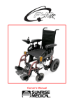
RX/
RXS
Owner’s Manual
Issue 5
47
RX/RXS
RX/RXS
Height adjustable armrests illustrated
How to use this manual
We at Sunrise Medical want you to get the best out of your Quickie RX/RXS
wheelchair. This Owner’s Manual will familiarise you with the chair and its
features. It contains hints on everyday usage and general care in addition to
information on the high quality standards which we adhere to and details
about the guarantee. This manual gives information on all features without
stating whether they are optional or standard. For this information refer to
the order/prescription form or your prescriber/supplier.
Your wheelchair will reach you in excellent condition having been personally
inspected before leaving our factory. By following the guidelines for
maintenance and cleaning on pages 39-40 your wheelchair will maintain its
first class condition and give you complete satisfaction.
For ease of use
Warning denotes a risk of personal injury or damage to
your chair and ! indicates points which will improve the performance and
safety of your chair.
Issue 4
RX/RXS
Contents
Introduction
page 1
Guarantee
page 2
Features and options
page 3
Safety tips
page 4
Using your chair
page 5-16
Footrests
page 17
Armrests
page 18-19
Wheel locks
page 20
Knee lever brakes
page 21
Grade aids
page 21
Backrests and Optima upholstery
page 22-23
Height adjustable push handles
page 23
Quick-release axles
page 24
Anti-tip tubes
page 24
Chair adjustments
page 25 - 34
Lap belt instructions
page 35 - 37
Transportation
page 38
Maintenance schedule
page 39
Cleaning guidelines, accessories and tools
page 40
Technical data
page 41
Sunrise Medical
page 42
RX/RXS
46
Issue 5
Introduction
Sunrise is dedicated to providing products of exacting quality which conform
fully and reliably to the requirements of their intended use.
This wheelchair is to be used to aid individuals with limited or no personal
mobility. The Quickie RX/RXS are suitable for both indoor and outdoor use.
The maximum user weight for these chairs is 113kg (250lb).
Sunrise is accredited to BS EN ISO 9001, which is the internationally
recognised standard for quality management systems. This approval ensures
we provide quality in all areas of our business from development through to
final delivery.
This product is manufactured to comply with the
‘Medical Device Directive’ 93/42/EEC.
If you have any queries about the use, maintenance or safety of your
wheelchair please contact your wheelchair prescriber/supplier. Sunrise
Medical will be pleased to answer any other questions that you may have and
can provide a list of approved Sunrise Medical agents on request to:
SUNRISE MEDICAL LIMITED
HIGH STREET WOLLASTON
WEST MIDLANDS DY8 4PS
ENGLAND
Telephone 01384 44 66 88 Fax. 01384 44 66 99
International Telephone +44 1384 44 66 88
Fax.+44 1384 44 66 99
www.sunrisemedical.co.uk
Serial Number:
Inspected by:
Your local dealer:
Your local dealer:
Issue 5
1
RX/RXS
Guarantee
7 Items of a consumable nature will not normally be
covered during the 12 month warranty period unless
such items have suffered undue wear as a direct
result of an original manufacturing defect. These
items include amongst others, lubricants, motor
brushes, upholstery, tyres, inner tubes, pushhandle
foam, brakes and similar parts. Batteries will be
covered by the warranty only where they have been
charged and maintained fully in accordance with the
manufacturer’s recommendations.
Your guarantee
The guarantee form is included in the Sunrise Pack,
which accompanies the chair on delivery. Please fill in
the relevant details and return to us to register your
entitlement. The guarantee is for your information.
THIS IN NO WAY AFFECTS YOUR STATUTORY
RIGHTS.
Sunrise Medical guarantees the frame, crossbrace and
wheelaxles on Quickie wheelchairs against defects in
materials and workmanship for the lifetime of the
original purchaser.
8 Under normal circumstances no responsibility will be
accepted where the goods have required repair
or replacement as a direct result of:
All Quickie wheelchairs, parts and components
(including frame components, axle plates, castors,
armrest, backrests etc.) are guaranteed against
defects in materials and workmanship for one year
from purchase date.
a) The goods or part not having been maintained in
accordance with the manufacturer’s
recommendations, where such exist and using
only the specified original equipment parts.
b) The goods or part having been damaged by
neglect, accident or improper use.
Warranty conditions
c) The goods or part having been altered from the
manufacturer’s specifications, or repairs having
been attempted prior to the designated repairer
being notified.
1 This warranty does not affect the statutory rights of
the Customer but if the Customer wishes to have
the benefit of the Company’s warranty the Customer
must comply with the provisions set out below.
2 In the event of a defect in the goods supplied
becoming apparent within the warranty period which
commences from the delivery date the Company
either itself or by an authorised dealer repair agent
will effect any necessary repair or replacement of
parts free of charge on condition that the Customer
complies with the following provisions of this
warranty.
3 Any part repaired or replaced during the warranty
period is warranted for the remainder of the duration
of that period.
4 The arrangements for repairs and service and the
designated repairer will be notified to the Customer
by the Company and will be confirmed at any time
on request.
5 ON A DEFECT OCCURRING DURING THE
WARRANTY PERIOD THE CUSTOMER MUST
NOTIFY THE DESIGNATED REPAIRER
IMMEDIATELY GIVING FULL INFORMATION AS
TO THE PROBLEM AND NO USE MUST BE MADE
OF THE GOODS AND NO ALTERATION OR
UNAUTHORISED REPAIRS MADE TO THE
GOODS PRIOR TO INSPECTION BY THE
DESIGNATED REPAIRER.
6 If the Customer is operating the Goods away from
the locality of the designated repairer the Customer
must contact the Company to obtain the name and
address of another repairer authorised by the
Company. If the Customer is operating the Goods
outside the UK the Customer must bear the
transport, insurance and packaging costs incurred in
having the Goods repaired or replaced by an
authorised repairer of the Company.
d) Fair wear and tear.
Please keep a note of your local service agent’s
address and telephone number in the space provided
on the previous page. In the event of a breakdown,
contact them and try to give all relevant details so they
can help you quickly.
The wheelchairs shown and described in this manual
may not be exactly the same in every detail as your
own model. However, all instructions are still entirely
relevant, irrespective of detail differences.
The manufacturer reserves the right to alter without
notice any weights, measurements or other technical
data shown in this manual. All figures, measurements
and capacities shown in this manual are approximate,
and do not constitute specifications.
Please remember to fill in and post the guarantee
registration card enclosed with this manual.
Sunrise Medical Limited recommend that you
do not undertake maintenance tasks other than
those explained in this manual. Your local
approved Sunrise Medical service agent is fully
trained by Sunrise Medical to carry out detailed
maintenance as and when required. Use only
genuine Sunrise Medical replacement parts.
Sunrise Medical Limited
High Street, Wollaston, West Midlands DY8 4PS England
Tel 01384 44 66 88 Fax 01384 44 66 99
www.sunrisemedical.co.uk
RX/RXS
2
Issue 5
Features and options
2
1
4
3
5
6
15
7
14
13
1
2
3
4
5
6
7
8
Issue 5
12
10
11
Height adjustable armrest
Push handle backrest tube
Angle adjustable backrest
Handrim
Full profile tyre
X spoked wheel
Quick-release axles
Adjustable axle plate (RXS)
9
8
8a
8a Axle bracket and threaded
axle (RX)
9 Wheel lock
10 Crossbrace
11 Swing-away release catch
12 Castor fork/wheel assembly
13 Flip up footplate
14 Swing-away hanger
15 Seat sling
3
RX/RXS
Safety tips
Wheelies
Anti-tip tubes
Doing a wheelie (tilting the
wheelchair backward to its balance
point) is dangerous, as the chair
may tip over. Wheelies should only
be performed by experienced
users. Do not attempt to learn or
practice this manoeuvre without the
aid of an attendant.
Under normal use, anti-tip tubes
will prevent the wheelchair from
tipping over backwards. Anti-tip
tubes are available from your local
wheelchair prescriber/supplier.
Sunrise Medical recommends antitip tubes for first time and less
experienced wheelchair users.
Footrests
Tyre pressure
The lowest point of the footrests
should be at least 63mm (2½") from
the ground to allow proper
clearance. Never stand on the
footrests because the chair may tip
over.
Warning:
Ensure that pneumatic tyres are
properly inflated. The correct tyre
pressure is 450 kilopascals/4.5 bar
(65 psi) for the pneumatic rear
wheels and 250 kilopascals/2.5 bar
(36 psi) for castor wheels. Low tyre
pressure may allow the rear wheels
locks to slip.
Never lift the wheelchair by the
swing-away footrests, or elevating
legrests or armrests. These parts
are detachable. Lifting the wheelchair
by them may cause damage to the
chair or injury to the user.
Armrests
Always secure swing-away
armrests before using the
wheelchair. Never lift the
wheelchair by the armrests. These
parts are detachable and lifting the
wheelchair by them may cause
damage to the chair and/or injury to
the user.
Kerbs, inclines, obstacles and
ramps
Always practice with a qualified
attendant before attempting to
negotiate kerbs, inclines or ramps
alone. It is important for you to
develop safe techniques suited to
your abilities. Do not attempt to go
up or down inclines greater than
10% (1 in 10).
Transfers
Guidelines on how to do a side
transfer are provided in this
manual, however, this is only one
method of transfer and you should
work with your wheelchair prescriber
/supplier to develop a technique
which best suits your abilities.
RX/RXS
4
Issue 5
Using your chair
Opening
Tilt the wheelchair towards you far
enough to take the weight off the
opposite wheel (Fig.1). Push down
with the palm of the hand on the seat
rail (1) closest to you until the
wheelchair has completely opened.
Allow the chair to return to an upright
position on all four wheels. Complete
the opening procedure by now
standing in front of the chair, placing
the palms of your hands on both seat
rails, and pressing down making sure
the seat rail snaps into the rail
saddles (2).
1
2
Warning:
Do not place your fingers between
the seat sling and frame rail during
this operation.
Fig. 1
Folding
Flip up the footplates to a vertical
position before folding the
wheelchair (Fig. 2). Standing to one
side of the chair, reach down and
grasp the seat sling at both the
front and the back between your
hands. Lift sharply to disengage the
seat sling rails from their frame
saddles. Once disengaged
continue with an upward lift until the
wheelchair is completely folded.
Fig. 2
Issue 5
5
RX/RXS
Using your chair
Water, snow and ice
3. Always use good posture and
proper body mechanics. When
you lift or support the rider or
chair, bend your knees slightly
and keep your back as upright
and straight as you can.
4. Unlock and rotate anti-tip tubes
up out of the way, to avoid a trip
or fall, when operating the chair
from the back.
5. Always lock the rear wheels and
lock anti-tip tubes in the down
position if you must leave the
rider alone, even for a moment.
Doing so will reduce the risk of a
tip over or loss of control of the
chair.
Contact with water, snow or ice
may affect the performance of your
wheelchair.
1. Never use your wheelchair in a
pool or other body of water.
2. If your chair becomes wet, or if you
use water to clean it, dry the chair
thoroughly as soon as you can.
When you need assistance
Warning:
If you fail to heed the following
warnings, a fall or tip over may
occur and cause severe injury to
you or to your attendant.
For the Rider:
You should make sure that persons
who assist you, read and follow all
warnings and instructions that apply
to that use. Before using this chair
each attendant must know what to
do to ensure safety.
Centre of balance
Warning:
The point where this chair will tip
forwards, backwards or to the side
depends on its centre of balance
and stability. If you fail to heed
these warnings a fall or tip over
may occur and cause severe injury
to you:
For Attendants:
1. Put the rider at ease. Tell the
rider what you plan to do and
explain what you expect the rider
to do.
2. Work with the rider’s doctor,
nurse or therapist to learn safe
methods best suited to your
abilities and those of the rider.
RX/RXS
1. The most important adjustment
to your chair is the position of the
rear axles. The further you move
the rear axles forward, the better
the chair manoeuvres, but the
more likely it is that your chair
will tip over backwards.
! Consult your doctor, nurse or
therapist to find out what axle
position is best for you.
6
Issue 5
Using your chair
Dressing and changing
clothes
Centre of balance (continued)
2. Changing the setup of this chair
increases the risk of a fall or tip
over. Be very careful if you make
a change to any of the following:
! The position of the rear axles,
the distance between the rear
wheels or the amount of rear
wheel camber.
! The distance between the
centre of the front castors and
rear wheels and the angle of the
castors.
3. To avoid a fall or tip over you
should:
! Have someone help you until
you know the balance points of
your chair and how to avoid a tip
over.
! Use anti-tip tubes until you
are sure you are not at risk of
tipping over.
4. The centre of balance and
stability of your chair are also
affected by:
! A shift in your body position,
posture or weight distribution.
! Riding your chair on a sloped
surface.
! Fitted seating systems.
Warning:
Your weight may shift if you dress
or change clothes while seated in
this chair. This may cause a fall or
tip over and severe injury to you. To
help prevent this you should:
1. Rotate the front castors to the
forward position.
2. Lock anti-tip tubes in the down
position if your chair has anti-tip
tubes.
3. Back your chair up against a wall
and lock both rear wheels.
Refer to the sections that follow to
learn how you can reduce the risk
of a fall or tip over by proper use of
this chair.
Issue 5
7
RX/RXS
Using your chair
Wheelies
(rear wheel balance)
Follow these steps when learning
to do a wheelie with help:
A wheelie is performed by
balancing on the rear wheels of
your chair, while the front castors
are raised off the ground. If done
safely, it can help you overcome
kerbs and other obstacles.
1. The attendant should be at the
rear of the chair, and must be
able to move with the chair to
prevent a tip over.
2. The attendant’s hands should be
beneath the push handles or
back brace ready to catch you if
you tip too far backwards.
3. When the attendant is in
position, place your hands on
the forward area of the
handrims.
4. Make a quick backward
movement of the rear wheels,
immediately followed by a hard
forward thrust. This will tilt the
chair backwards and lift the
castors from the ground.
Try to find the balance point,
which is the point where you will
not fall backwards or forwards.
5. Maintain your balance by small
movements of the handrims.
Warning:
It is dangerous to do a wheelie, as
you may fall or tip over backwards
and suffer a severe injury. Make
sure that you heed these warnings:
1. Consult your doctor, nurse or
therapist to find out if you are a
good candidate to learn to do a
wheelie.
2. Do not try to do a wheelie unless
you are a highly skilled rider or
unless you have help.
3. Make sure that anti-tip tubes are
up, out of the way, so they do
not interfere.
4. When learning to do a wheelie,
make sure that this chair has
push handles. The attendant
needs secure points to hold the
rear of the chair to prevent the
user from tipping over
backwards.
RX/RXS
8
Issue 5
Using your chair
Doorways and obstacles
1. Avoid reaching or leaning if you
must shift your weight to do so.
Moving forwards in your seat
may cause the chair to tip
forward. Always keep your lower
back in contact with the
backrest. Ask for help or use a
device to extend your reach.
2. Never reach with both hands. If
you do so, you may not be able
to catch yourself to prevent a fall
if the chair tips.
3. Never lean backwards to reach
for an object unless your chair
has anti-tip tubes and they are
locked in the down position.
4. If you must reach or lean from
your wheelchair:
! rotate the front castors to the
forward position. To do this,
move your chair past the object,
then back up alongside it.
! place your chair as close as
you can to the object you wish to
reach.
! steady yourself by firmly
grasping an armrest with one
hand. This will help you prevent
a fall if the chair tips.
! avoid putting pressure on the
footrests while reaching. This
may cause the chair to tip
forward.
! do not lock the rear wheels.
This creates a tipping point and
makes a fall or tip over more
likely.
Warning:
1. As much as possible ensure that
the floor areas where you use
the chair are level and free of
obstacles by:
! removing or covering
threshold strips between rooms,
! installing a ramp at entry or
exit doors.
2. If your chair has anti-tip tubes,
make sure you lock them in the
down position before you go
over an obstacle.
3. Keep both your hands on the
handrims. If you fail to do so,
you may lose control of your
chair and tip over.
4. Do not propel your chair by
pushing or pulling on an object.
Never pull yourself through a
doorway by grabbing the
doorjambs with one or both hands.
5. To help correct the centre of
balance of your chair you
should:
! lean your upper body forward
slightly as you go up over an
obstacle.
! press your upper body
backward as you go down from
a higher to a lower level.
Reaching or leaning
Warning:
Reaching or leaning affects the centre
of balance of your chair if you fail to
heed these warnings, a fall or tip over
may occur and cause severe injury to you.
Issue 5
9
RX/RXS
Using your chair
Slopes and hills
Warning:
Going up or down a slope (Fig. 3) or
riding on the side of a hill (Fig. 4)
will change the centre of balance of
your chair. If you fail to heed these
warnings you may suffer a severe
injury from a tip over, fall or loss of
control:
1. Lean or press your body uphill to
help correct the change in the
centre of balance.
2. Avoid turning on a slope or the
side of a hill, as a tip over is
likely. Always go as straight up
and straight down as you can.
3. Be very careful if you must climb a
slope greater than 10% (1 in 10).
Ask for help if the slope may be
beyond your ability.
! On a steep slope, anti-tip
tubes may not prevent a tip over.
! On a steep slope, you may
not be able to reach the top
without stopping. If you have to
stop turn the chair sideways on
to the hill otherwise you may lose
control and tip over.
4. Always control your speed when
going downhill. If you go too fast,
you may not be able to control
your chair. Ask for help if the
slope may be beyond your ability.
! You can control your speed by
keeping constant pressure on the
handrims.
! Never use the rear wheel locks to
try to slow or stop your wheelchair.
Doing so is likely to cause you to
veer out of control or tip over.
RX/RXS
10% MAXIMUM SLOPE
Fig. 3
10% MAXIMUM SLOPE
Fig. 4
10
Issue 5
Using your chair
Transfers
7. Be careful of the footrests. To
avoid a trip or fall when you
transfer, you should:
! Make sure that your feet do
not hang up or get caught in the
space between the footrests.
! Avoid putting weight on the
footrests as the chair may tip
forwards.
! If you can, remove or swing
the footrests out of the way.
Warning:
If you fail to heed these warnings, a
fall or tip over may occur and cause
severe injury to you:
1. Transfers require good balance
and agility and are very
dangerous. Be aware that there
is a point during each transfer
when the wheelchair seat is not
below you.
2. To avoid a fall, you should:
! learn how to position your
body and how to support
yourself during the transfer.
! work with your doctor, nurse
or therapist to learn safe transfer
methods.
! have someone help you until
you are sure you can perform
safe transfers on your own.
3. Wherever possible position your
wheelchair as illustrated in Fig. 5
and 6.
4. Always lock the rear wheels
before you transfer to keep the
chair from rolling.
Locking the rear wheels will not
always keep your chair from
sliding away from you or tipping.
5. Rotate the front castors forward
to make the chair more stable.
6. If your chair has armrests, make
sure that they are out of the way
and do not interfere.
Fig. 5
Fig. 6
Issue 5
11
RX/RXS
Using your chair
Kerbs and single steps
Warning:
If you fail to heed these warnings, a
fall or tip over may occur and cause
severe injury to you or others:
1. Never try to climb or descend a
kerb or step alone unless you
are a skilled rider and:
! you can safely do a wheelie;
and
! you are sure you have the
upper body strength needed to
do so.
2. Unlock and rotate anti-tip tubes
up, out of the way, so they do
not interfere.
3. Do not try to climb a kerb or step
more than 100mm (4") high
unless you have help; your chair
may exceed its balance point
and tip over (Fig. 7).
4. When you have an attendant,
make sure that the chair has
push handles. The attendant
must have secure points to
hold the rear of the chair.
RX/RXS
100mm (4") MAXIMUM KERB HEIGHT
Fig. 7
12
Issue 5
Using your chair
Tips for descending a kerb or
single step with help
Read and follow the warnings for
attendants. To help the rider
descend a kerb or single step in a
backward direction:
1. Check to make sure that push
handle grips will not rotate or slip
off.
2. Always stay behind the
wheelchair (Fig. 8).
3. Before you reach the edge of the
kerb or step, turn the chair
around and pull it backwards.
4. While looking over your
shoulder, carefully step back
until you are off the kerb or step
and standing on the lower level.
5. Pull the chair towards you until
the rear wheels reach the edge
of the kerb or step. Then allow
the rear wheels to slowly roll
down onto the lower level
(Fig.9).
6. When the rear wheels are safely
on the lower level, tilt the chair
back to its balance point. This
will lift the front castors off the
kerb or step.
7. Keep the balance position and
take small steps backwards.
Turn the chair around and
carefully lower the front castors
to the ground.
100mm (4") MAXIMUM KERB HEIGHT
Fig. 8
100mm (4") MAXIMUM KERB HEIGHT
Fig. 9
Issue 5
13
RX/RXS
Using your chair
Tips for climbing a kerb or
single step with help
Read and follow the warnings for
attendants. To help the rider mount
a kerb or single step in a forward
direction:
1. Always stay behind the
wheelchair.
2. Face the kerb and tilt the chair
up on the rear wheels so that the
front castors clear the kerb or
step (Fig. 10).
3. Move forward, placing the front
castors on the upper level as
soon as you are sure that they
are past the edge.
4. Continue forward until the rear
wheels contact the face of the
kerb or step (Fig. 11). Lift and roll
the rear wheels to the upper
level.
100mm (4") MAXIMUM KERB HEIGHT
Fig. 10
100mm (4") MAXIMUM KERB HEIGHT
Fig. 11
RX/RXS
14
Issue 5
Using your chair
Moving a chair and rider up
or down stairs
2. The attendant at the rear is in
control. He or she tilts the chair
back to its balance point
(Fig. 12).
3. A second attendant at the front
firmly grasps a non-detachable
part of the front frame and lifts
the chair up and over one step at
a time.
4. The attendants reposition
themselves on the next step up
and repeat the same procedure
for each step. When the landing
is reached, return the chair to its
upright position.
Warning:
Where possible, avoid carrying out
this manoeuvre to prevent
attendant injury.
Read and follow the warnings for
attendants. If you fail to heed these
warnings a fall or tip over may
occur and cause severe injury to
the rider and/or attendants:
1. Always use two or more
attendants when moving a chair
and rider up or down stairs
(Fig. 12).
2. Make sure that this chair has
push handles and that the grips
will not rotate or slip off. The
attendant at the rear needs
secure hand-holds to bear the
weight of the chair and rider.
3. Use only non-detachable parts of
the main frame as hand-holds.
4. Make sure that the rider is
secure in the chair, with his or
her feet, arms and hands safely
out of the way of any obstacles.
Tips for climbing stairs with
help
Read and follow the warnings for
attendants. Follow these steps
when helping the rider climb stairs:
1. Move the chair and rider
backwards up the stairs.
Fig. 12
Issue 5
15
RX/RXS
Using your chair
Tips for descending stairs with
help
Read and follow the warnings for
attendants. Follow these steps
when helping the rider descend
stairs:
1. Move the chair and rider forward
down the stairs (Fig. 13).
2. The attendant at the rear is in
control. He or she tilts the chair
to the balance point of the rear
wheels and rolls it to the edge of
the top step.
3. A second attendant stands firmly
on a lower step and grasps the
chair frame. Both attendants
lower the chair one step at a
time by letting the rear wheels
roll over the step edge.
4. The attendants move to the next
step down and repeat the same
procedure for each step. When
the landing is reached return the
chair to its upright position.
RX/RXS
Fig. 13
16
Issue 5
Chair features
Swing-away footrests
Swing-away footrests (Fig. 14)
enable easier forward transfers
from your chair to be performed.
2
Releasing and removing
footrests
To release the footrest, push the
release latch (1) towards the frame
(2), and rotate the footrest outward.
To remove the footrest from the
chair lift vertically from this position.
1
Fig. 14
Replacing footrests
To replace the footrest (Fig. 15),
place the swingaway pivot saddle
(3) into the receiver (4) on the
frame (2) with the footrest facing
outward from the frame. Rotate the
footrest inward until it locks into
place on the locking stud (5).
3
2
4
5
Fig. 15
Issue 5
17
RX/RXS
Chair features
Swing-away armrests
Swing-away removable armrests
(Fig. 16) are installed by simply
sliding the armrest tube (1) into the
receiver (2). To remove simply pull
the armrest upwards until the tube
clears the receiver. To swing-away
pull the armrest upwards
approximately 25mm (1") until it will
swing freely away from the chair. To
return the armrest to its normal
position pull it towards you until you
feel it drop and lock into position.
1
2
Fig. 16
RX/RXS
18
Issue 5
Chair features
Height-adjustable armrests
To install armrests, slide the outer
arm post (1) into the receiver (2).
The armrest will automatically lock
in place (Fig. 17).
4
To adjust the armrest height, rotate
the release lever (3) to the second
stop (Fig. 17B). Slide the armrest
pad (4) up or down to the desired
height and return the lever to the
locked position. Push the arm pad
until the upper arm post locks firmly
in place.
3
1
2
To detach the armrest, rotate the
release lever to the first stop and
remove the armrest (Fig. 17C). To
replace the armrest, slide the
armrest back into the receiver and
return the release lever to the
locked position (Fig. 17).
5
Fig. 17
Fig. 17B
The armrest can be adjusted to
remove free play in the receiver
and inner arm post (Fig. 17). To
tighten or loosen the fit of the outer
post in the receiver, first loosen the
four 10mm A/F bolts (5) two on
each side of the receiver. With the
armrest in the receiver, squeeze
the receiver to achieve the desired
fit, then tighten the four bolts. To
adjust the fit of the inner arm post,
two set screws (6) are installed in
the outer arm post (Fig 17D). Turn
the set screws in or out until the
desired fit is achieved using a 3/32"
Allen key.
Fig. 17C
6
Fig. 17D
Issue 5
19
RX/RXS
Chair features
Wheel locks
High mount push-to-lock wheel
locks are shown in Fig. 18. The
wheel lock mounts on a clamping
system (1) and is correctly set prior
to leaving the factory. To apply the
wheel lock simply push the
operating lever (2) forwards until
you feel it go over centre, and the
grip bar (3) grips the tyre (4). The
operating lever (2) can have a
detatchable extension which can
be removed to create space for
side transfers. When the wheel lock
is applied remove the operating
lever extension by pulling it off the
brake. Refit when you are
reseated. It is attatched by a cord
to the wheel lock and cannot fall
off.
2
1
4
3
Fig. 18
Scissor wheel lock
Scissor wheel locks are shown in
Fig. 19. The locks mount on clamping
systems (1) and are correctly set prior to
leaving the factory. To apply the wheel
lock pull the operating lever (2) forwards
until you feel it go over centre, and the
grip arm (3) grips the tyre (4). Scissor
locks can also be mounted on the lower
frame tube (Fig. 19B). When mounted in
the lower position the left hand lock must
be mounted on top of the right hand
frame, and vice versa.
Fig. 19
Warning:
Wheel locks are not brakes and
they are not designed to slow down
the chair when it is moving. Wheel
locks, prevent the rear wheels from
turning when the chair is stationary.
RX/RXS
4
3
1
2
Fig. 19B
20
Issue 5
Chair features
Knee lever brakes (RXS only)
2
1
The knee lever brake (Fig. 20) mounts
on a clamping system (1) and is correctly
set prior to leaving the factory. To apply
the knee lever brake simply push the
operating lever (2) forwards until you feel
it go over centre, and the grip bar (3)
grips the tyre (4). The operating lever (2)
can have a detatchable extension which
can be removed to create space for side
transfers. When the knee lever brake is
applied remove the operating lever
extension by pulling it off the brake.
Refit when you are reseated. It is
attatched by a cord to the knee brake
and cannot fall off.
Warning:
Knee lever brakes are not designed to
slow down the chair when it is moving.
Knee lever brakes, prevent the rear
wheels from turning when the chair is
stationary.
3
4
Fig. 20a
1
Knee brake
Operating position and adjustment
instructions for the kneebrake wheel lock
are shown in Fig. 21.
Fig. 20b
2
Slaken the two screws (1) on the wheel
lock clamp and slide the brake to
achieve the correct wheel lock gap, then
retighten.
The wheel lock gap (2) (which is the gap
between the nearest point of the wheel
lock and the tyre) should be 3mm with
pneumatic tyres (tyres filled with air) and
5mm with solid tyres, when the wheel
lock is in the released position.
1
Grade aids (RXS only)
Grade aids are shown in Fig. 21.
To operate the aid push the lever (1)
downwards. You will feel it go over a
spring loaded lock, when it has done so it
is in the operating position. When the aid
is not required pull the lever up over the
spring loaded lock.
Issue 5
Fig. 21
21
RX/RXS
Chair features
Backrest
The backrest is available in three
height ranges with 50mm (2")
height adjustment in each range
(Fig. 22). The upholstery comes
with front and rear insert slots. The
rear slot (with no opening)
accommodates a standard back.
The front slot (with top opening) is
used for push handle backs.
Fig. 22
Angle adjustable backrest
(RXS only)
An angle adjustable backrest is
shown in Fig. 23 which has 15O of
adjustment in 3O degree
increments. See adjustments
section for more details.
0
-3
3
6
12
Fig. 23
RX/RXS
22
Issue 5
Chair features
Optima upholstery (RXS only)
Your RXS wheelchair can be
supplied with Optima backrest
upholstery and stabiliser bar
(Fig. 24 and 25). Adjustable Velcro®
straps allow the backrest to be
shaped to follow the exact profile of
your back. This will enhance both
the comfort and support that this
chair will give you.
Fig. 24
Height adjustable push handles
(RXS only)
1
2
Height adjustable push handles (1)
are shown in Fig. 25. To adjust the
height of the handles loosen the
adjustment knob (2). Set the push
handle to the required position and
re-tighten the knob.
Stabiliser bar (RXS only)
To provide these chairs with
additional rigidity a stabiliser bar (3)
can be fitted. To remove the bar,
prior to folding the chair, the levers
(4) need to be depressed on both
sides of the bar; whilst keeping the
levers depressed the bar can be
removed, by pulling it backwards.
Issue 5
3
4
Fig. 25
23
RX/RXS
Chair features
Quick-release axles
6
To remove quick-release axles
(Fig. 26) simply press the quickrelease button (1) which is located
in the wheel hub (2), and grip the
wheel through the spokes (3)
around the hub and pull the axle
out of its sleeve (4). To replace,
slide the axle into the sleeve until
the release button ‘pops’ out and
the two locking pins (5) are visible
on the inside (6) of the sleeve.
Warning:
The axle is not secure until the
outside quick-release button pops
out to its fully extended position, and
the locking pins (5) on the inside of
the axle are in the locked position.
4
3
5
2
1
Fig. 26
Anti-tip tubes
Press the rear (Fig. 27) anti-tip
release lever (1) on the anti-tip tube
(2) so that both locking pins (3) are
drawn into the tube, and insert it
into the anti-tip tube receiver (4).
Ensure the two locking pins are
located and locked into the receiver
mounting holes.
2
1
3
4
Turning anti-tip tubes
In some instances it can be wise to
rotate the tubes through 180O
(Fig. 27), hold the release pins (1)
in and rotate the tubes through
180O, allowing the locking pins (3)
to click into position.
RX/RXS
1
3
Fig. 27
24
Issue 5
Chair adjustments
Footplate height adjustment
To adjust the footplate (1) height,
loosen the screw (2), using a 4mm
Allen key located as shown
(Fig. 28), and set the footplate
height to the required position.
Tighten the screw to 5-8Nm torque.
1
2
Fig. 28
Footplate height adjustment
Angle adjustable footplate
2
To adjust the footplate (1) height,
loosen the screw (2), located as
shown, with a 4 mm Allen key and
set the footplate height to the
required position. Tighten using the
Allen key to a torque setting of
5-8Nm (Fig. 29).
1
Fig. 29
Issue 5
25
RX/RXS
Chair adjustments
Footplate angle adjustment
Angle adjustable footplate
To adjust the footplate angle
(Fig. 30), loosen the screws (1) with
a 4mm Allen key sufficiently to
allow the footplate to be rotated to
the required angle. When at the
required angle tighten the Allen
screws using a torque spanner to
8-10Nm torque setting.
Footplate depth adjustment
1
2
To adjust the depth of the footplate
(Fig. 30), remove the two screws
(1) and relocate the footplate to the
desired depth position through the
choice of a different set of holes (2)
Refit the screws and tighten to the
settings given above.
Fig. 30
Backrest angle adjustment
(RXS only)
The angle of the backrest (Fig. 31)
can be adjusted through increments
of 3O, between -3O to 12O , by using
the backrest adjusting mechanisms
(1) which are located on the upper
rear frame tubes. Loosen the screw
(2) and removing screw (3) using a
6mm Allen key (on both sides of
the chair). Rotate the backrest (4)
to the required position and replace
the screw (3) into the hole which
bears the appropriate marking in
degrees (5). Tighten both screws to
24Nm torque.
1
4
2
3
0
3
6
-3
12
5
Fig. 31
RX/RXS
26
Issue 5
Chair adjustments
Adjusting optima upholstery
(RXS only)
1
To adjust the upholstery (Fig. 32)
first lift up the back flap (1) covering
the strips, with the user sitting in
the chair, proceed to loosen or
tighten each individual strap (2).
It is necessary to follow the profile
of the users back (In practice this
will generally mean tightening the
straps around the lumbar region,
and loosening the straps around
the posterior and upper back).
These adjustments should only be
performed by a qualified therapist.
2
Fig. 32
Adjusting anti-tip tube height
To adjust the height of the anti-tip
tube (Fig. 33) press in the two
locking pins (1) on the anti-tip
wheel assembly and move the
wheel assembly to the desired
position. There are three sets of
holes (2) for adjustment. Ensure
the locking pins are correctly locked
into the required holes prior to
using the wheelchair.
1
2
Fig. 33
Issue 5
27
RX/RXS
Chair adjustments
Knee lever brake (RXS only)
and wheel lock adjustment
1
2
To adjust, loosen the two screws
(1) on each clamp (2), and the
screws (3 - Fig. 35) on the
underside of each clamp (note the
screws are shown removed for
clarity). Using a 5mm Allen key turn
one of the screws anticlockwise ¼
turn (Fig. 34 and 35). Repeat the
process with the other screws.
Loosen the four screws until the
clamp can slide freely. Slide the
clamp towards the rear wheel until
the grip bar (4) embeds into the
tyre (5) approximately 4mm (3/16")
when in the locked position. Tighten
the screws to a torque setting of
15Nm. Some adjustments to the
wheel lock position can be
accomplished without moving the
clamp. To adjust, loosen the four
screws as above. Slide the
mounting bar (6) forward or
backwards and rotate it to the
correct angle position. The grip bar
should embed into the tyre
approximately 4mm (3/16") when in
the locked position. Tighten the
screws to a torque setting of 15Nm.
5
4
2
1
4
Fig. 34 Quickie wheel locks
1
2
Warning:
5
Wheel locks/knee lever brakes when
properly adjusted, prevent the rear
wheels from turning when the chair
is stationary. Always adjust the
wheel locks after making any
changes to the rear axle sleeves
position, so that the grip bar embeds
into the tyre approximately 4mm (3/
16") when in the locked position.
RX/RXS
6
3
6
4
Fig. 35 Knee lever brake
28
Issue 5
Chair adjustments
Seat height (RXS)
Seat height can be adjusted by
moving the axle sleeve (1) vertically
(Fig. 36) in the axle plate slot (2). This
allows a 114mm adjustment in 13mm
increments. First loosen the 28mm A/F
outer retaining nut (3) sufficiently to
allow the sleeve and locating plate (4)
to slide, and position the sleeve and
plate at the required height, ensuring
that the keys (5) are located in the
required keyways (6). Tighten the
retaining nut using a torque wrench to
a setting of 45Nm.
Note:
After adjusting the axle position, the
front castors must be checked for
adjustment (see page 32, Fig. 42).
2
4
5
6
1
3
Fig. 36
Seat height adjustment (RX)
To adjust the seat height (Fig. 37),
remove the wheel by unscrewing
the 19mm A/F retaining nut (1, if
quick-release axles are not fitted),
the wheel spacer (2, if fitted), and
the axle (3). Move the axle to the
desired position using one of the
two holes (4) in the axle plate and
replace the axle and tighten to
45Nm torque setting, replace the
wheel, spacer and retaining nut and
tighten to 45Nm.
Note:
After adjusting the axle position, the
front castors must be checked for
adjustment (see page 32, Fig. 42).
4
2
1
3
Fig. 37
Issue 5
29
RX/RXS
Chair adjustments
Wheelbase (RXS)
To adjust the rear wheelbase
(Fig. 38), loosen the inner (1) and
outer (2) axle sleeve retaining
28mm A/F nuts. Screw the nuts
along the axle sleeve (3) until the
desired wheelbase is found.
Tighten the nuts with a torque
wrench to a setting of 45Nm.
Warning
Always ensure that there is
sufficient clearance between the
wheel and the frame after carrying
out this adjustment.
1
2
3
Fig. 38
Centre of gravity (RXS)
4
The cente of gravity (Fig. 39) is
adjusted by removing the four
retaining nuts (1) and screws (2)
from the axle plate (3), sliding the
axle plate along the top and bottom
frame members (4) to the required
position and refitting the nuts and
screws in the predrilled holes (5) in
the frame. The spanner size is
10mm A/F, the screws and nuts
must be tightened to 8-10Nm
torque.
Note:
After changing the centre of gravity
always check:
Angle of castors (see page 32,
Fig. 42).
Both axles are in identical positions.
RX/RXS
1
2
3
4
5
Fig. 39
30
Issue 5
Chair adjustments
Centre of gravity (RX)
To adjust the centre of gravity (Fig. 40)
remove the wheel, by unscrewing
the 19mm A/F retaining nut (1, if
quick release axles are not fitted),
the wheel spacer (2, if fitted), the
axle (3), the two bracket retaining
bolts (4) and nuts (5) using 10mm
A/F spanners. Move the bracket (6)
to the rear position, as shown, and
replace the bolts and retaining nuts
and tighten them to 8-10Nm torque
setting, replace the axle in the
required hole (7) and tighten to
81Nm. Relace the wheel, spacer and
retaining nut and tighten to 45Nm.
Note:
After adjusting the axle position the
front castors must be checked for
adjustment (see page 32, Fig. 42).
5
4
3
2
1
7
6
Fig. 40
2
Camber adjustment (RXS)
The rear wheel camber is preset at
the factory at 2O (Fig. 41), but it can
be adjusted by loosening the axle
plate (1) top retaining nuts (2) and
screws (3) and removing the bottom
retaining nuts (4) and screws (5)
ensuring that the camber washer (6)
is retained. Insert an additional
camber washer and re-assemble
using 10mm A/F spanners,
tightening the nuts and screws to 810Nm torque.
3
1
4
6
5
Fig. 41
Issue 5
31
RX/RXS
Chair adjustments
Castor angle adjustment
For optimum performance, the
castor housing should always be
perpendicular to the floor (Fig. 42).
This adjustment is made with
eccentric (offset) bolts (1). To
change the angle, place the chair
on a flat surface (such as a table.)
Remove the 10mm A/F bolt nuts (2)
from the back side of the castor
housing (3). You will note that the
castor housing is slotted at the side
for adjustment. Place a large right
angled object (4) against the flat
surface and the front surface of the
castor bearing housing (5). This will
align the castor stem rotational axis
perpendicular to the floor surface.
Rotate the bolts independently until
they fall into position. When the
alignment is satisfactory, re-tighten
the two retaining bolts to 8-10Nm
torque. Repeat the process for the
other castor.
3
2
1
5
4
90°
Fig. 42
1 FORWARD FACING
Castor reversibility
The castor plate (Fig. 43) is
generally mounted in a forwards
facing position (1). However, if
additional footrest clearance is
necessary, the castor housing can
be reversed (2), by moving the left
housing on to the right side of the
frame, and the right housing on to
the left side of the frame.
After reversing the castors follow
the procedure for castor angle
adjustment to reset the angle of
each castor.
RX/RXS
2 REAR FACING
Fig. 43
32
Issue 5
Chair adjustments
Chair height adjustment
Two-hole castor forks (Fig. 44)
allow you to interchange 127mm
(5"), 152mm (6") and 203mm (8")
castor wheels and to adjust the
seat height. To adjust, remove the
13mm A/F axle bolt (1) and nut (2)
with 13mm A/F spanners and
remove the castor wheel (3). Either
change the castor wheel size and/
or position the castor wheel upward
or downward in the desired predrilled holes (4) 25mm (1") apart on
the castor fork (5). Replace the bolt
and tighten to 27Nm torque. Follow
castor angle adjustment on
page 32, Fig. 42.
5
2
3
4
1
Fig. 44
Inside mounted castors
To inside mount the castors
(Fig. 45), reverse the positions of
the castor assemblies. Remove the
castor assemblies (1) from the
frame (noting their positions).
Inside mount the right castor on the
left side and the left castor on the
right side. For correct refitting follow
the instructions on page 32, Fig. 42
(Castor angle adjustment),
ensuring that the castors are at the
correct angle and the retaining nuts
and bolts are tightened to the
correct torque setting 8-10Nm.
1
Fig. 45
Issue 5
33
RX/RXS
Chair adjustments
Castor adjustment
1
To remove play from the castor
stem (Fig. 46), remove the dust
cover (1) by prising it off. Tighten
the nut (2) with a 19mm A/F socket
spanner until all play is removed,
yet still allows the castor fork
assembly to rotate freely. Replace
the dust cover by snapping it back
in place.
2
Fig. 46
Seat sling tensioning
The seat sling (Fig. 47) can be
re-tensioned through the use of
Velcro® panels underneath the
seat. Remove the No 2 Philips
screws (1) retaining the left side of
the seat sling with a No 2 Philips
screwdriver, re-adjust the Velcro® to
bring the sling to its correct tension.
Replace the screws and tighten to
5-8Nm torque.
1
Fig. 47
RX/RXS
34
Issue 5
Lap belt instructions
Note:
Lap belts are fitted as positional aids, and are not suitable as transportation
restraints.
Step 1
Step 1
Positioning belt kit. The Positioning
belt kit contains, one positioning
belt, three tri glide buckles and two
cable ties.
Step 2
Step 2
To assemble the positioning belt.
Take the positioning belt strap and
thread through the tri-glide. Repeat
on both ends of positioning belt.
Step 3
Step 3
To fit the positioning belt to the
chair. Take the positioning belt strap
and wrap around back post.
Step 4
Step 4
Thread the positioning belt back
through the tri-glide to form a loop
around the back post. Thread
positioning strap through tri-glide as
shown in step 5.
Issue 5
35
RX/RXS
Lap belt instructions
Step 5
Step 5
To secure the positioning belt to the
chair. Take one of the cable ties
supplied and thread through the
positioning belt strap. Then wrap
around the frame and fasten
together. DO NOT over tighten
positioning belt. Repeat steps 3-5
with both ends of positioning belt.
Step 6
Step 6
To adjust the positioning belt use
the tri-glide buckles and the
fastening buckle.
Tri-glides
Fastening buckle
Step 7
Step 7
Generally the Lab Belt should be
fixed so that the straps sit at an
angle of approximately 45°, and
when corretly adjusted should not
allow user to slip down in the seat.
Step 8
Step 8
When fastened check space
between belt and user, when
correctly adjusted it should be
possible to insert the flat of the
hand between the beld and user.
RX/RXS
36
Issue 5
Lap belt instructions
The positioning belt can be used on the Quickie RXS, Quickie 2, Breezy SLTL
and Quickie 2 Millennium wheelchairs.
Quickie RXS:
Advice to client
The positioning belt must only be fitted by an
approved Sunrise Medical dealer / agent. The
positioning belt should only be adjusted by a
professional, or a Sunrise Medical approved
dealer / agent.
Quickie 2:
Quickie 2 Millennium:
The positioning belt must be checked on a daily
basis to ensure they are adjusted correctly (see
step 7) and are free from any obstruction or
adverse wear.
Sunrise Medical does not encourage the
transportation of any person in a vehicle using
this positioning belt as a method of restraint.
Please see Sunrise Medical transit booklet for
further advice on transportation.
Maintenance:
Check lap belt, and securing components, at
regular intervals for any sign of frays, or
damage. Replace if necessary.
Breezy SL/TL:
Issue 5
NOTE:
The lap belt should be adjusted to suit the
end user as detailed above. Sunrise Medical
recommend that the length and fit of the belt
be checked on a regular basis to reduce the
risk of the end user inadvertently re-adjusting
the belt to an excessive length.
37
RX/RXS
Transportation
8. Any detachable accessories or
components of the wheelchair must be
removed and stored securely in the
vehicle luggage compartment during
transportation.
Transportation in vehicles
This wheelchair has been crash tested
in its standard configuration. However,
due to safety risks Sunrise Medical do
not recommend the transportation of
people in their wheelchairs.
9. The Tie down restraints should be
fitted to the main frame of the wheelchair
as indicated by the karabiner stickers,
and in the User Manual, and not to any
other part of the chair.
Should a person need to be transported
in the wheelchair on transport systems,
the following should be adhered to:
10. The Tie Down restraints should be
attached as close as possible at an
angle of 45°, and tightened securely in
accordance with the restraint
manufacturers’ instructions.
1. The wheelchair must be positioned
forward facing.
2. For tie down points on the
wheelchair, please look for the tie-down
symbols on the wheelchair.
11. The wheelchair parking brakes must
be firmly applied.
3. A head restraint must be fitted and
suitably positioned at all times during the
transportation.
4. If possible, remove seat cushion to
create a lower centre of gravity.
5. The chair is crash-tested, and has
satisfied the Dynamic test requirements
of ISO 7176-19.
6. The wheelchair must be secured by
a 4-point Tie Down Restraint system,
conforming to ISO 10542 part 2.
7. The occupant must be restrained
independently of the wheelchair by a lap
and diagonal safety belt, conforming to
ISO 10542 part 3.Sunrise Medical
postural lap belts are for postural
support only, and not suitable as
restraints during transportation.
RX/RXS
38
Issue 5
Maintenance schedule
All Quickie RX / RXS wheelchairs leave the factory inspected and adjusted
for immediate use. Continuous use will require routine maintenance and
adjustments, especially if original settings are altered. Initial adjustment,
carried out by your wheelchair prescriber/supplier, should accommodate
your body structure and personal preference.
The following table gives an indication as to when routine maintenance
checks should be made which will help sustain the life and efficiency of your
wheelchair.
Quickie RX / RXS range
CHECK LIST
GENERAL
1. Tyre pressure - 450 kilopascals/4.5 bar (65 psi)
(rear wheels).
250 kilopascals/2.5 bar (36 psi)
(castor wheels).
2. Wheel locks Check for loose fasteners.
3. Castor (front) wheels Check that the swing-away mechanism and castor
wheel rotate freely.
4. Roll of wheelchair Check that the wheelchair rolls in a straight line
with no excess drag or pull.
6. Folding of the backrest Check the backrest folds and opens smoothly.
Check for loose fasteners.
7. Armrests (swing-away) Check that all fasteners are secure and that all
mechanisms work freely.
5. Seat sling and back uphostery Check for wear or ‘sagginess’ in the upholstery.
8. Complete inspection, safety check and service
should be made by an authorised Sunrise Medical
supplier or wheelchair agent.
9. Frame and axle plates
Spoke Tension Maintenance
Check for loose or broken spokes every 3 months.
Tighten loose spokes so that they are the same tension as the others.
Contact an authorised dealer / maintenance centre to replace broken
spokes.
Issue 5
39
RX/RXS
Cleaning guidelines, accessories and tools
Accessories
Cleaning guidelines
Anti-tip tubes
Armrest pouch
Backpack
Caddy
Crutch holder
Leg strap
Neoprene impact guards
Positioning belts:
Long Velcro® style 170cm (67")
Short Velcro® style 145cm (57")
Long buckle 163cm (64")
Short buckle 137cm (54")
Seat pouch
Spoke guard - clear
Spoke guard - black
Step tube - left
Step tube - right
Swing-away tray table
Tool kit
Touch up paints
In addition to the maintenance
checks on the previous page,
general cleaning of both the frame
and upholstery should be
undertaken. To maintain its
appearance the upholstery should
be cleaned regularly. Light soiling
can be removed by sponging with a
mild detergent and warm water,
wiping in the direction of the
texture. Rinse off with clean water
before allowing to dry.
DO NOT PUT UPHOLSTERY
IN A DRYER.
Do not use bleach or solvents.
If dirt is ingrained, the surface
should be scrubbed with a soft
brush.
The frame should be cleaned
regularly with a non-abrasive
cleaner followed by polishing with a
non-abrasive automotive wax.
JAY seating and positioning
systems are available.
Contact Customer Services for
individual requirements
Tools
To maintain the wheelchair you will
need the following tools:An adjustable spanner
2, 3, 4, 5, 6 and 7mm Allen keys
3/32" Allen key
A spoke key
10, 13, 17 and 19mm A/F spanners
Phillips No. 2 screwdriver
RX/RXS
40
Issue 5
Technical data
Quickie RX
Overall length with legrest
Overall width
Folded length
Folded width
Folded height
Total mass
Mass of heaviest part
Static stability downhill
Static stability uphill
Static stability sideways
Seat plane angle
Effective seat depth
Effective seat width450mm
Seat surface height at front edge
Backrest angle
Backrest height
Footrest to seat distance
Leg to seat surface angle
Armrest to seat distance
Front location of armrest structure
Handrim diameter
Horizontal location of axle
Minimum turning radius
1021mm min.-1090mm max.
657mm
748mm min.-848mm max.
328mm
913mm
15kg - 11kg for the kids version
13.5kg
19.5O min.-27O max.
17O min.-12.5O max.
24.5O min.-24.5O max.
13.7O
436mm
474mm
20.7O
825mm
350mm min.-495 mm max.
116O
227mm
100mm
530mm
30mm to rear. 60mm to front
760mm
Quickie RXS
Overall length with legrest
Overall width
Folded length
Folded width
Folded height
Total mass
Mass of heaviest part
Static stability downhill
Static stability uphill
Static stability sideways
Seat plane angle
Effective seat depth
Effective seat width461mm
Seat surface height at front edge
Backrest angle
Backrest height
Footrest to seat distance
Leg to seat surface angle
Armrest to seat distance
Front location of armrest structure
Handrim diameter
Horizontal location of axle
Minimum turning radius
Issue 5
991mm min.-1064mm max.
740mm
679mm min.-1105mm max.
330mm
679mm min.-730mm max.
14kg - 11kg for the kids version
11kg
5O
9O
5O
10.4O
587mm
463mm
12.9O min.-24O max.
505mm min.-605mm max.
355mm min.-465 mm max.
104O
264mm min.-383mm max.
261mm min.-475mm max.
533mm
38mm to front. 77mm to rear
710mm
41
RX/RXS
Sunrise Medical
Your new Quickie RX/RXS is manufactured in the West Midlands by Sunrise
Medical. With over 30 years experience, we are one of the longest
established mobility equipment manufacturers in the UK. All our
Wheelchairs, Powerchairs, Scootas and Stairlifts undergo rigorous tests to
ensure that they meet our requirements of comfort, safety and durability.
Our success is based on the strong traditions of quality, value for money
and genuinely caring for our customers.
We pride ourselves not only on designing and building the most innovative
products, but also on our commitment to offer an excellent standard of
customer service both during and after sale.
In addition to your new Quickie RX/RXS, Sunrise also manufacture oxygen
concentrators, nebulizers and hoists. We have a vast range of aids to daily
living which include the Merlin Bath Lifter, bed accessories and walking sticks.
Should you require any information on our full range of products please call
us on 01384 44 66 88 or contact us at:
Sunrise Medical Limited
High Street Wollaston
West Midlands DY8 4PS
www.sunrisemedical.co.uk
Sunrise Medical Limited
High Street, Wollaston, West Midlands DY8 4PS England
Tel +44 (0)1384 44 66 88 Fax +44 (0)1384 44 66 99
www.sunrisemedical.co.uk