Transcript
700
ELECTRICAL / PLUMBING SPECIFICATIONS
SERIES
ELECTRICAL
PLUMBING
A 115 volt, 6OHz, 15 amp circuit breaker and electrical supply are required. A separate circuit, servicing each base and
tall unit, is necessary. Follow the National Electrical Code
and local codes and ordinances when installing the receptacle.
For units with an automatic ice maker, rough in the water
supply line. Connect a 1/4-inch OD copper line to the house
supply being sure to use an easily accessible shut-off valve
between the supply and the refrigerator. This shut-off valve
should not be installed behind the unit. Do not use "selfpiercing" valves. A saddle valve (part #4-20-088-0) is available from your distributor/dealer. A line filter is required
when the water supply has a high mineral content. The ice
maker operates on water pressure of 20 to 100 psi. In some
cases a reverse osmosis water filter system may not be able
to maintain the minimum pressure.
IMPORTANT NOTE: The electrical outlet must be placed so
the grounding prong is to the right of the thinner blades.
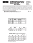
The outlet must be flush with the back wall. Refer to illustration 1, on page 24 for exact placement.
WARNING
Illustration 1, on page 24 shows the water line's precise
placement. When routing the water through the side walls,
you must place the water line within 1/2-inch of the floor
and as close as possible to the back wall. The line must be
routed around the anti-tip bracket so it clears the bracket
and the leveling "feet" of the unit. Refer to the top view in
illustration 1. Regardless of the routing, allow for 27 inches
of excess copper tubing to remain outside the wall or floor
for easy connection to the unit.
All Sub-Zero 700 Series units are equipped with a 3prong grounding plug and they must be plugged into a
mating 3-prong grounding-type wall receptacle.
Do not use an extension cord, or two prong adapter.
Electrical ground is required on this appliance.
Do not under any circumstances remove the power
supply cord ground prong.
IMPORTANT NOTE: Do not route water supply line in front
of the compressor tray. The tray must be slid forward for
service.
PRE-INSTALLATION SPECIFICATIONS
TOP VIEW
112
(38)
13 12
TOP VIEW
(152)
CL
CL
13 12
(343)
(343)
15 12
The 700 Series Installation Guide packed with the appliance
will give you step-by-step procedures for making sure the
unit is installed properly.
6
ANTI-TIP
BRACKET
9
(229)
(394)
27
ANTI-TIP
BRACKET
WATER LINE
SIDE ENTRY
LOCATIONS
(686)
WATER LINE
BOTTOM ENTRY
LOCATION
112 (38)
27
(686)
112 (38)
FRONT VIEW
SIDE VIEW
27
(686)
NOTE: ORIENT GROUND PRONG
TO RIGHT AS SHOWN
WATER LINE
REAR ENTRY
LOCATION
ANTI-TIP
BRACKET
3
4
(19)
4 12
(114)
80
(2032)
3 (76)
HEIGHT OF
BASE UNIT
13 (330)
2 12
9
(229)
(64)
15 12
34 12
(394)
(876)
ANTI-TIP
BRACKET
WATER LINE
SIDE ENTRY
LOCATION
24
(610)
Illus. 1
1
4
(6)
ANTI-TIP
BRACKET