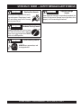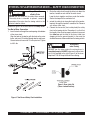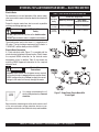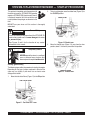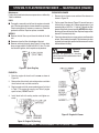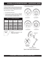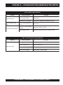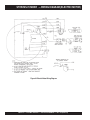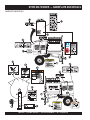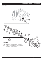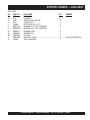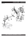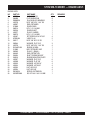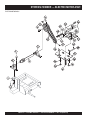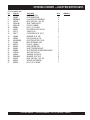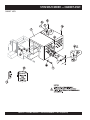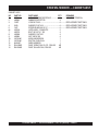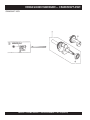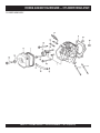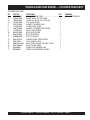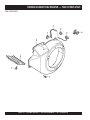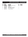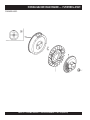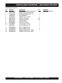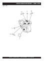
1
OPERATION AND PARTS MANUAL MODEL MS-70 PLASTER AND MORTAR MIXER (GASOLINE ENGINE/ELECTRIC MOTOR) Revision #3 (03/26/10) THIS MANUAL MUST ACCOMPANY THE EQUIPMENT AT ALL TIMES. Engine exhaust and some of its constituents, and some dust created by power sanding, sawing, grinding, drillingandotherconstructionactivities contains chemicals known to the State of California to cause cancer, birth defects and other reproductive harm. Some examples of these chemicals are: Leadfromlead-basedpaints. Crystallinesilicafrombricks. Cementandothermasonryproducts. Arsenicandchromiumfromchemically treatedlumber. Your risk from these exposures varies, depending on how often you do this type of work. To reduce your exposure to these chemicals: ALWAYS work in a well ventilated area, and work with approved safety equipment, such as dust masks that are specially designed to filter out microscopic particles. PAGE 2 — STOW MS-70 MIXER — OPERATION MANUAL — REV. #3 (03/26/10) HERE'S HOW TO GET HELP PLEASE HAVE THE MODEL AND SERIAL NUMBER ON-HAND WHEN CALLING STOW MAIN OFFICE Post Office Box 6254 Carson, Ca 90749 Email: [email protected] Internet: www.stowmfg.com PARTS DEPARTMENT 800-427-1244 310-537-3700 SERVICE DEPARTMENT 800-421-1244 310-537-3700 TECHNICAL ASSISTANCE 800-478-1244 WARRANTY DEPARTMENT 800-421-1244, EXT. 279 310-537-3700, EXT. 279 SALES DEPARTMENT 310-661-4242 877-289-7869 (877-BUY-STOW) 888-252-STOW FAX: 310-537-1986 FAX: 800-672-7877 FAX: 310-637-3284 FAX: 310-537-4259 FAX: 310-631-5032 FAX: 310-537-1173 FAX: 310-604-9237 © COPYRIGHT 2004, STOW CONSTRUCTION EQUIPMENT STOW Construction Equipment and the STOW logo are registered trademarks of STOW and may not be used, reproduced, or altered without written permission. All other trademarks are the property of thier respective owners and used with permission. This manual MUST accompany the equipment at all times. This manual is considered a permanent part of the equipment and should remain with the unit if resold. The information and specifications included in this publication were in effect at the time of approval for printing. Illustrations are based on the MS-70 Plaster/Mortar Mixer. STOW Construction Equipment reserves the right to discontinue or change specifications, design or the information published in this publication at any time without notice and without incurring any obligations. To find the latest revision of this publication, visit our website at: www.stowmfg.com STOW MS-70 MIXER — OPERATION MANUAL — REV. #3 (03/26/10) — PAGE 3 STOW MS-70 PLASTER/MORTAR MIXER — TABLE OF CONTENTS STOW MS-70 — Plaster/Mortar Mixer Here's How To Get Help .................................................. 3 Table Of Contents ........................................................... 4 Parts Ordering Procedures ............................................. 5 Specifications ................................................................. 6 Dimensions ..................................................................... 7 Safety Messages Alert Symbols ................................. 8-9 Rules For Safe Operation ........................................ 10-11 Towing Guidelines ......................................................... 12 Safety Chain Connection .............................................. 13 Operation and Safey Decals ......................................... 14 General Information ...................................................... 15 Basic Mixer Components ............................................. 16 Basic Engine Components ........................................... 17 Electric Motor .......................................................... 18-19 Paddle Blade Adjustment ............................................. 20 Inspection ................................................................ 21-22 Start-up Procedures ................................................ 22-24 Operation and Shut-Down ............................................. 25 Maintenance (Engine) .............................................. 26-27 Maintenance (Mixer) ................................................ 28-32 Troubleshooting (Engine) ......................................... 33-34 Troubleshooting (Mixer/Electric Motor) ......................... 35 Electric Motor Wiring Diagram ...................................... 36 Explanation of Code In Remarks Column ..................... 38 Suggested Spare Parts ................................................ 39 HONDA GX240K1HA2 ENGINE Air Cleaner Assembly .............................................. 58-59 Camshaft Assembly ................................................ 60-61 Carburetor Assembly ............................................... 62-63 Control Assembly .................................................... 64-65 Crankcase Cover Assembly .................................... 66-67 Crankshaft Assembly .............................................. 68-69 Cylinder Barrel Assembly ........................................ 70-71 Cylinder Head Assembly ......................................... 72-73 Fan Assembly ......................................................... 74-75 Flywheel Assembly ................................................. 76-77 Muffler Assembly .................................................... 78-79 Fuel Tank Assembly ................................................ 80-81 Ignition Coil Assembly ............................................. 82-83 Piston Assembly ..................................................... 84-85 Recoil Starter Assembly ......................................... 86-87 Gear Reduction Assembly ....................................... 88-89 Labels ...................................................................... 90-91 Terms and Conditions of Sale — Parts .................. 92 Component Drawings Nameplate and Decals ............................................ 40-41 Frame Assembly ..................................................... 42-43 Paddle Shaft Assembly ........................................... 44-45 Steel Drum Assembly ............................................. 46-47 Drum and Paddle Shaft Complete Assembly ........... 48-49 Axle Assembly ........................................................ 50-51 Engine Assembly .................................................... 52-53 Electric Motor Assembly ......................................... 54-55 Cabinet Assembly ................................................... 56-57 NOTE Specifications and are subject to change without notice. PAGE 4 — STOW MS-70 MIXER — OPERATION MANUAL — REV. #3 (03/26/10) STOW MS-70 MIXER — PARTS ORDERING PROCEDURES When ordering parts, please supply the following information: ❒ ❒ ❒ ❒ ❒ ❒ ❒ Dealer account number Dealer name and address Shipping address (if different than billing address) Return fax number Applicable model number Quantity, part number and description of each part Specify preferred method of shipment: ✓ FedEx or UPS Ground Note: Unless otherwise indicated by customer, all ✓ FedEx or UPS Second Day or Third Day orders are treated as “Standard Orders”, and will ship within 24 hours. We will make every effort to ✓ FedEx or UPS Next Day ship “Air Shipments” the same day that the order is ✓ Federal Express Priority One received, if prior to 2PM west coast time. “Stock ✓ DHL Orders” must be so noted on fax or web forms. ✓ Truck Here’s how to get help... Please have the model and serial number on hand when calling. STOW MAIN OFFICE 18910 Wilmington Ave. 800-421-1244 Carson, CA 90746 FAX: 310-537-3927 Email: [email protected] Internet: www.stowmfg.com SALES DEPARTMENT 310-661-4242 Fax: 310-604-9237 877-289-7869 (877-BUY-STOW) PARTS DEPARTMENT 800-427-1244 FAX: 800-672-7877 310-537-3700 FAX: 310-637-3284 SERVICE DEPARTMENT 800-421-1244 FAX: 310-537-4259 310-537-3700 TECHNICAL ASSISTANCE 800-478-1244 FAX: 310-631-5032 WARRANTY DEPARTMENT 800-421-1244, EXT. 279 FAX: 310-537-1173 310-537-3700, EXT. 279 STOW CONSTRUCTION EQUIPMENT A DIVISION OF MULTIQUIP INC. POST OFFICE BOX 6254 CARSON, CA 90749 888-252-STOW [888-252-7869] 310-537-3700 FAX: 310-537-1986 E-MAIL: [email protected] FAX: 800-556-1986 INTERNET: www.stowmfg.com Place Your Parts Order Via Web or Fax For Even More Savings! (Domestic USA Dealers Only) Extra Discounts! All parts orders which include complete part numbers and are received by our automated web parts order system, or by fax qualify for the following extra discounts: Ordered via Fax Standard orders 3% Stock orders ($750 list and above) 10% Web 5% 10% Special freight allowances when you order 10 or more line items via Web or Fax!** FedEx Ground Service at no charge for freight No other allowances on freight shipped by any other carrier. **Common nuts, bolts and washers (all items under $1.00 list price) do not count towards the 10+ line items. NOTE: DISCOUNTS ARE SUBJECT TO CHANGE Direct TOLL-FREE access to our Parts Department: Toll-free nationwide — 800-427-1244 Toll-free FAX — 800-6-PARTS-7 (800/672-7877) STOW MS-70 MIXER — OPERATION MANUAL — REV. #3 (03/26/10) — PAGE 5 STOW MS-70 PLASTER/MORTAR MIXER — SPECIFICATIONS TABLE 1. MIXER SPECIFICATIONS Capacity 7.0 cu. ft (198 liters) Bag Capacity 1-1/2 to 2-1/2 bags Weight 788 lbs. (357 kg.) Height W/Dump Handle 73 in. (185 cm.) Discharge Height 21 in. (53 cm.) Drive V-Belt/Gear Dump Action Manual Table 2. Specifications (Engine & Electric Motor) Model Type Engine/Electric Motor 1.5 HP, 115/230, Single Phase Electric Motor N/A Displacement 14.81 cc N/A 8.0 H.P./3600 R.P.M. 1.5 H.P./1725 RPM Approx. 1.59 U.S. Gallons (6 Liters) N/A Unleaded Gasoline N/A 2-1/3 pints N/A Centrifugal Fly-weight Type N/A Recoil Star t N/A 14.0 x 16.9 X 16.1 in. (355 X 430 X 410 mm) 13.3 x 8.7 X 9.06 in. (338 X 220 X 230 mm) 55.1 lbs. (25 Kg.) Approx. 22 lbs. (10 Kg.) Max Output Lube Oil Capacity Speed Control Method Star ting Method NOTE Air-cooled 4 stroke, OHV, Horizontal Shaft Gasoline Engine 2.90 in. X 2.30 in. (73 mm x 58 mm) Fuel Dry Net Weight BALDOR 35L229S302 Bore X Stroke Fuel Tank Capacity Dimensions (L x W x H) HONDA GX240K1HA2 In accordance with our established policy of constant improvement, we reserve the right to amend these specifications at any time without notice. PAGE 6 — STOW MS-70 MIXER — OPERATION MANUAL — REV. #3 (03/26/10) STOW MS-70 PLASTER/MORTAR MIXER — DIMENSIONS TABLE 3. DIMENSIONS Description Dimensions in. (cm) Length (w/ Tow Bar) 67 in. (170 cm) Width 50 in. (127 cm) Height 56 in. (142 cm) Figure 1. Dimensions STOW MS-70 MIXER — OPERATION MANUAL — REV. #3 (03/26/10) — PAGE 7 STOW MS-70 MIXER — SAFETY MESSAGE ALERT SYMBOLS FOR YOUR SAFETY AND THE SAFETY OF OTHERS! HAZARD SYMBOLS Safety precautions should be followed at all times when operating this equipment. Failure to read and understand the Safety Messages and Operating Instructions could result in injury to yourself and others. Potential hazards associated with the operation of a MS-70 Plaster/Mortar Mixer will be referenced with Hazard Symbols which appear throughout this manual, and will be referenced in conjunction with Safety Message Alert Symbols. WARNING This Owner's Manual has been developed to provide complete instructions for the safe and efficient operation of the STOW Model MS-70 mortar and plaster mixer. Refer to the engine manufacturers instructions for data relative to its safe operation. NOTE Before using this mixer, ensure that the operating individual has read and understands all instructions in this manual. SAFETY MESSAGE ALERT SYMBOLS The three (3) Safety Messages shown below will inform you about potential hazards that could injure you or others. The Safety Messages specifically address the level of exposure to the operator, and are preceded by one of three words: DANGER, DANGER You WILL be KILLED or SERIOUSLY INJURED if you DO NOT follow these directions. WARNING You CAN be KILLED or SERIOUSLY INJURED if you DO NOT follow these directions. CAUTI CAUTION You CAN be INJURED if you DO NOT follow these directions. Lethal Exhaust Gas Hazards Engine exhaust gases contain poisonous carbon monoxide. This gas is colorless and odorless, and can cause death if inhaled. NEVER operate this equipment in a confined area or enclosed structure that does not provide ample free flow air. WARNING Explosive Fuel Hazards Gasoline is extremely flammable, and its vapors can cause an explosion if ignited. DO NOT start the engine near spilled fuel or combustible fluids. DO NOT fill the fuel tank while the engine is running or hot. DO NOT overfill tank, since spilled fuel could ignite if it comes into contact with hot engine parts or sparks from the ignition system. Store fuel in approved containers, in well-ventilated areas and away from sparks and flames. WARNING Burn Hazards Engine components can generate extreme heat. To prevent burns, DO NOT touch these areas while the engine is running or immediately after operations. Never operate the engine with heat shields or heat guards removed. WARNING Respiratory Hazards ALWAYS wear approved respiratory protection when required. PAGE 8 — STOW MS-70 MIXER — OPERATION MANUAL — REV. #3 (03/26/10) STOW MS-70 MIXER — SAFETY MESSAGE ALERT SYMBOLS CAUTION Rotating Parts Hazards NEVER operate equipment with covers, or guards removed. Keep fingers, hands, hair and clothing away from all moving parts to prevent injury. CAUTION CAUTION Equipment Damage Hazards Other important messages are provided throughout this manual to help prevent damage to your light tower, other property, or the surrounding environment. Accidental Starting Hazards ALWAYS disconnect the electrical power cord from the electric motor, when the mixer is not in use and place the ON/OFF switch in the OFF position. CAUTION Eye and Hearing Hazards ALWAYS wear approved eye and hearing protection. STOW MS-70 MIXER — OPERATION MANUAL — REV. #3 (03/26/10) — PAGE 9 STOW MS-70 PLASTER/MORTAR MIXER — RULES FOR SAFE OPERATION DANGER Read this manual! Failure to follow instructions in this manual may lead to serious injury or even death! This equipment is to be operated by trained and qualified personnel only! This equipment is for industrial use only. The following safety guidelines should always be used when operating the STOW MS-70 mortar and plaster mixer: GENERAL SAFETY ■ DO NOT operate or service this equipment before reading this entire manual. ■ This equipment should not be operated by persons under 18 years of age. ■ NEVER operate this equipment without proper protective clothing, shatterproof glasses, steel-toed boots and other protective devices required by the job. ■ NEVER operate this equipment when not feeling well due to fatigue, illness or taking medicine. ■ NEVER operate this equipment under the influence of drugs or alcohol. ■ ALWAYS wear proper respiratory (mask), hearing and eye protection equipment when operating the mixer. ■ NEVER place hands inside the drum while the blades are rotating. ■ Whenever necessary, replace nameplate, operation and safety decals when they become difficult read. ■ Manufacture does not assume responsibility for any accident due to equipment modifications. ■ NEVER use accessories or attachments, which are not recommended by Multiquip for this equipment. Damage to the equipment and/or injury to user may result. ■ NEVER touch the hot exhaust manifold, muffler or cylinder. Allow these parts to cool before servicing engine or mixer. ■ High Temperatures – Allow the engine to cool before adding fuel or performing service and maintenance functions. Contact with hot! components can cause serious burns. ■ The engine section of this mixer requires an adequate free flow of cooling air. NEVER operate the mixer in any enclosed or narrow area where free flow of the air is restricted. If the air flow is restricted it will cause serious damage to the mixer or engine and may cause injury to people. Remember the mixer's engine gives off DEADLY carbon monoxide gas. ■ ALWAYS refuel in a wellventilated area, away from sparks and open flames. ■ ALWAYS use extreme caution when working with flammable liquids. When refueling, stop the engine and allow it to cool. DO NOT smoke around or near the machine. Fire or explosion could result from fuel vapors, or if fuel is spilled on a hot engine. ■ NEVER operate the mixer in an explosive atmosphere or near combustible materials. An explosion or fire could result causing severe bodily harm or even death. ■ Topping-off to filler port is dangerous, as it tends to spill fuel. ■ Stop the engine when leaving the mixer unattended. ■ Block the unit when leaving or when using on a slope. ■ Maintain this equipment in a safe operating condition at all times. WARNING Starting the Mixer Engine NEVER! start the engine or engage the paddle arms when the drum is in the discharge (down) position. PAGE 10 — STOW MS-70 MIXER — OPERATION MANUAL — REV. #3 (03/26/10) STOW MS-70 PLASTER/MORTAR MIXER — RULES FOR SAFE OPERATION ■ ALWAYS stop the engine before servicing, adding fuel and oil. ■ NEVER run engine without air filter. Severe engine may occur. ■ ALWAYS service air cleaner frequently to prevent carburetor malfunction. ■ ALWAYS check the machine for loosened threads or bolts before starting. ■ ALWAYS be sure the operator is familiar with proper safety precautions and operations techniques before using mixer. ■ ALWAYS store equipment properly when it is not being used. Equipment should be stored in a clean, dry location out of the reach of children. ■ DO NOT operate this equipment unless all guards and safety devices are attached and in place. ■ CAUTION must be exercised while servicing this equipment. Rotating and moving parts can cause injury if contacted. ■ When towing, an adequate safety chain must be fastened to the frame. See Towing Guidelines section in this manual. ■ Keep all inexperienced and unauthorized people away from the equipment at all times. ■ Unauthorized equipment modifications will void all warranties. ■ Check all fasteners periodically for tightness. Also check towing tongue bolt, lock nut and wheel lug nuts for wear. ■ Stop the engine and disconnect the spark plug before allowing anybody’s hands in the mixing drum. ■ NEVER pour or spray water over the engine or electric motor. Stand Clear of the Mixer when in use Always stand clear of the dump handle when the mixer is in operation. Any binding of material between the mixer blades and the drum will cause the drum handle to quickly move and could cause bodily harm. WARNING TRANSPORTING ■ ALWAYS shutdown engine before transporting. ■ Tighten fuel tank cap securely and close fuel cock to prevent fuel from spilling. ■ Drain fuel when transporting mixer over long distances or bad roads. MAINTENANCE ■ NEVER lubricate components or attempt service on a running mixer. ■ ALWAYS allow the mixer a proper amount of time to cool before servicing. ■ Keep the mixer in proper running condition. ■ Fix damage to the mixer immediately and always replace broken parts. ■ Dispose of hazardous waste properly. Examples of potentially hazardous waste are used motor oil, fuel and fuel filters. ■ DO NOT use food or plastic containers to dispose of hazardous waste. EMERGENCIES ■ ALWAYS know the location of the nearest fire extinguisher and first aid kit. ■ In emergencies always know the location of the nearest phone or keep a phone on the job site. Also know the phone numbers of the nearest ambulance, doctor and fire department. This information will be invaluable in the case of an emergency. ■ Depending on type of mixer, test the ON/OFF switch for either the gasoline engine or electric motor before operating. The purpose of these switches is to shut down the engine or motor of the mixer. ■ Refer to the HONDA Engine Owner's Manual for engine technical questions or information recommended by Multiquip for this equipment. Damage to the equipment and/or injury to user may result. STOW MS-70 MIXER — OPERATION MANUAL — REV. #3 (03/26/10) — PAGE 11 STOW MS-70 PLASTER/MORTAR MIXER — TOWING GUIDELINES Towing Safety Precautions Regularly Inspect Towing Components To reduce the possibility of an accident while transporting the mixer on public roads, always make sure that the mixer towing components and the towing vehicle are in good operating condition and both units are mechanically sound. CAUTION ■ ALWAYS make sure that the fuel valve lever is in the OFF position (gasoline models only). ■ Check wheel mounting lug nuts with a torque wrench. Torque wheel lug nuts as described in the maintenance section of this manual. ■ Check tightness of U-clamp nuts, torque suspension hardware as referenced in the maintenance section of this manual. ■ Avoid sudden stops and starts. This can cause skidding, or jackknifing. Smooth, gradual starts and stops will The following list of suggestions should be used when towing improve gas milage. the mixer: ■ Check with your county or state safety towing regulations department before towing your mixer. ■ Avoid sharp turns to prevent rolling. Tow Bar to Vehicle Connection (Coupler Only) ■ Make sure that the hitch and coupling of the towing vehicle are rated equal to, or greater than the trailer "gross vehicle 1. Check the vehicle hitch ball, and mixer's coupler for signs of wear or damage. Replace any parts that are weight rating" (GVWR). worn or damaged before towing. ■ ALWAYS inspect the hitch and coupling for wear. NEVER tow the mixer with defective hitches, couplings, chains Replacing CAUTION etc. Towing Components ■ CHECK the tire air pressure on both the towing vehicle If the mixer tow bar is deformed or damaged, replace the and the trailer. Also check the tire tread wear on both entire tow bar. NEVER tow the mixer with a defective vehicles. tow bar. There exists the possibility of the mixer separating from the towing vehicle. ■ ALWAYS make sure the mixer is equipped with a "Safety Chain". ■ ALWAYS attach trailer's safety chain to the frame of 2. Use only a 2-inch ball diameter (towing vehicle), this will match the mixer's 2-inch coupler. Use of any other ball towing vehicle. diameter will create an extremely dangerous condition ■ ALWAYS make sure that the towing vehicle's directional, which can result in separation of the coupler and ball or backup, and brake lights are working properly. ball failure. ■ Remember in most cases the maximum speed unless otherwise posted for highway towing is 55 MPH, however 3. After tow bar has been connected to mixer (see next page), attach mixer's coupler to the hitch ball on the before towing your mixer, check your local state, and towing vehicle securely and make sure the lock lever is county vehicle towing requirements. Recommended offin the down position (locked). road towing is not to exceed 10 or 15 MPH or less Mixer Tow Bar Vehicle Connection (Pintle and Loop) depending on type of terrain. ■ Place chocked blocks underneath wheels to prevent 1. Make sure the bumper on the towing vehicle is equipped to handle either a pintle or loop type tow bar configuration. rolling, while parked, if disconnected from towing vehicle. 2. After tow bar has been connected to mixer (see next page), secure either type of tow bar to the towing vehicle, ■ Inflate tires to correct pressure, inspect tires for cuts, following state and county towing regulations. and excessive wear. See Table 9 (Tire Wear Troubleshooting). ■ When towing of the mixer is required, place the drum in 3. As a minimum, use a 1/2-inch bolt and nylock nut grade 5 when securing the tow bar to the towing vehicle and to the up position (mouth facing upwards) and lock the drum the unit being towed. latch. PAGE 12 — STOW MS-70 MIXER — OPERATION MANUAL — REV. #3 (03/26/10) STOW MS-70 PLASTER/MORTAR MIXER — SAFETY CHAIN CONNECTION CAUTION Always Tow with a Safety Chain NEVER! tow the mixer with the safety chain removed. The safety chain is intended to prevent complete separation of the mixer from the towing vehicle in the event of a tow bar failure. Reference Figure 2 for the installation of the safety chain. Tow Bar to Mixer Connection 1. Insert the tow bar through the round opening at the bottom of the mixer stand. Align the hole on the tow bar with the hole on the mixer frame, and insert 1/2-inch bolt through tow bar and frame. Secure tow bar to frame with 1/2-inch nylock nut. Tighten to 40 ft.-lbs. 2. Route the safety chain through the holes just above the tow bar, located on each side of the mixer stand. Loop the chain together and place under the tow bar. Secure the loop with the connector link. 3. extend the safety chain along the length of the tow bar, looping it through the tow bar's connector link. Remove any excess chain slack. 4. Connect the free end of (clevis safety hook) the safety chain to the towing vehicle. Remember it is critical that the length of the chain be properly adjusted, to prevent the draw bar and the front of the mixer stand from dropping to the the ground (contact) in the event the draw bar becomes disconnected from the towing vehicle. CAUTION Drum Saftey when Towing DO NOT tow the mixer unless the mixing drum is completely empty. ALWAYS make sure the drum latch pin is fully engaged to the right (Figure 3) of the drum stop block. This will keep the drum from rotating. Figure 3. Drum Latch Pin (Tow or Locked Position) Figure 2. Tow Bar and Safety Chain Installation STOW MS-70 MIXER — OPERATION MANUAL — REV. #3 (03/26/10) — PAGE 13 MS-70 PLASTER/MORTAR MIXER — OPERATION AND SAFETY DECALS Machine Safety Decals The STOW MS-70 mortar and plaster mixer is equipped with a number of safety decals. These decals are provided for operator safety and maintenance information. Figure 4 below illustrates these decals as they appear on the machine. Should any of these decals become unreadable, replacements can be obtained from your dealer. Figure 4. Mixer Operation and Safety Decals PAGE 14 — STOW MS-70 MIXER — OPERATION MANUAL — REV. #3 (03/26/10) STOW MS-70 PLASTER/MORTAR MIXER — GENERAL INFORMATION Application The STOW MS-70 series mixers (drum capacity of 7.0 cu. ft./198 liters) are shipped completely assembled and have been factory tested and are ready for use. This mixer is only intended for the production of plaster and mortar. The mixer must be used for its intended purpose and is not suitable for the mixing of flammable or explosive substances. The mixer must not be used in an explosive atmosphere. This mixer has a batch capacity between 2-1/2 and 3-1/2 bags. Power Plants The STOW plaster and mortar mixer can be powered by a Honda GX240K1HA2air-cooled, 4-stroke gasoline engine or a 1.5 HP electric motor. Refer to Table 2 for specific engine or electric motor data information. Electrical If mixer is equipped with an electric motor, make sure that the power being supplied to the motor corresponds to the voltage rating label on the motor. Supplying the wrong voltage to the electric motor will cause severe electrical damage to the motor. Always make sure the OFF/ON switch on the electric motor is in the OFF position before applying power. It is strongly recommended when inserting the mixer's power cord into a receptacle, that a G.F.C.I. (Ground Fault Current Interrupter ) receptacle be used (115 VAC applications). Extension Cables The extension cable should be a 3-wire configuration that includes a ground wire that conforms to UL code. The wire cross section must be a minimum of 2.5 mm2. Choose an extension cord of adequate current carrying capacity as referenced in Table 6. Remember cable distance affects the current-voltage capacity of the extension cable. Ensure that the extension cable is carefully laid out avoiding wet areas, sharp edges and locations where vehicles might run over it. Avoid allowing the extension cable to be trapped underneath the mixer. Unroll the extension cable fully or it will overheat and could catch fire. Make sure that all extension cable connections are dry and safe. Replace any defective or badly worn extension cable immediately. Hardware Check all hardware on the mixer before starting. Periodically inspect all hardware. Loose hardware can contribute to early component failure and poor performance. Use Table 4 as general guideline when torqueing of mixer hardware is required. Remember to keep all mixer hardware components tight. Table 4. Hardware Torque Recommendations Hardware Diameter Torque (ft-lbs) 5/16-inch x 18 14 3/8-inch x 16 24 3/8-inch x 24 37 1/2-inch x 13 39 1/2-inch x 13 (Grade 8) 90 Engine Maintenance For basic engine maintenance, refer to the engine maintenance section in this manual. For a more detailed engine maintenance, refer to the Honda Engine Owner's manual furnished with the engine. STOW MS-70 MIXER — OPERATION MANUAL — REV. #3 (03/26/10) — PAGE 15 STOW MS-70 PLASTER/MORTAR MIXER — BASIC MIXER COMPONENTS 8. Mixing Paddles — Used in the mixing of material. This unit uses four different types of paddles to provide a fast uniform mix. 9. Bag Cutter— This feature allows compound mixing bags to be opened easily, therefore allowing the contents of the bag to fall directly into the mixing drum. 10. Safety Grill — Provided for operator safety. This safety grill is designed to keep hands and solid objects out of the mixing drum when in use. This grill should be closed at all times when mixer is in use. DO NOT remove the grill or grill opening bar. Keep the grill clean by washing it down daily. 11. Dump Handle — Pull this handle downward to dump the contents of the drum. Push the handle upward to return the drum to its vertical position. Figure 5. Mixer Components Figure 5 illustrates the basic components and controls of the STOW MS-70 mixer 1. Tires Ply — The tire ply (layers) number is rated in letters; This mixer uses 13-inch 4-ply tires. 2. Engine Cover — Lift this cover to gain access to the engine compartment. 3. Belt Slip Lever — When starting this lever should be move upward and to the left. For mixing place the lever in the down position. See attached decal located adjacent to lever. 4. ON/OFF Switch (electric) — This switch is provided on mixers with electric motors. To gain access to this switch, lift the engine cover. When activated it will shut down the electric motor. 5. ON/OFF Switch (gasoline) — This switch is provided on mixers with gasoline engines only and is located on the side of the engine cover. When activated it will shut down the engine. 6. 7. Latch — Use this latch to secure the engine compartment cabinet. Drum Bearing — There is on each end of the mixing drum, a sealed bearing. Bearings are packed and sealed at the factory and require no further maintenance. 12. Safety Grill Lock Handle — To prevent injury to hands and arms, the safety grill should ALWAYS be locked when the mixing of plaster or mortar is required. Also when transporting the mixer the safety grill should be locked. The safety grill should only be un-locked when cleaning of the blades and drum is required. 13. Pivot Point/Zerk Fitting — There is, on each end of the mixing drum a zerk grease fitting. These fittings lubricate the dumping mechanism. Lubricate both fittings at least twice a week. 14. Dump Handle Release Pin — Pull this pin outward (spring loaded) to release the drum, then pull down on the dump handle to place the drum in the dump position. When drum is in dump position, pin will automatically lock drum. 15. Steel Mixing Drum — Mixing materials such as mortar, plaster are to be placed into this drum for mixing. Always clean the drum after each use. 16. Tow Bar/Coupler — This mixer uses a 2-inch coupler or pintle towbar. 17. Safety Chain — This mixer uses a 3/16-inch thick, 72inches long zinc-plated saftey chain. ALWAYS connect the safety chain when towing. 18. Forklift Pockets – When lifting of the mixer is required, use these fork lift pockets to lift the mixer. Remember to insert the forks of the forklift a minimum of 24 inches into the lift pockets. 19. Chock Blocks — Place these blocks (not included as part of the mixer package) under each mixer wheel to prevent rolling. PAGE 16 — STOW MS-70 MIXER — OPERATION MANUAL — REV. #3 (03/26/10) STOW MS-70 PLASTER/MORTAR MIXER — BASIC ENGINE COMPONENTS Figure 6. Engine Controls and Components INITIAL SERVICING 5. The engine (Figure 6) must be checked for proper lubrication and filled with fuel prior to operation. Refer to the manufacturers Engine manual for instructions & details of operation and servicing. Fuel Valve Lever – OPEN to let fuel flow, CLOSE to stop the flow of fuel. 6. Choke Lever – Used in the starting of a cold engine, or in cold weather conditions. The choke enriches the fuel mixture. 1. 7. Air Cleaner – Prevents dirt and other debris from entering the fuel system. Remove wing-nut on top of air filter cannister to gain access to filter element. Fuel Filler Cap – Remove this cap to add unleaded gasoline to the fuel tank. Make sure cap is tightened securely. DO NOT over fill. DANGER Explosive Fuel Hazard NOTE Adding fuel to the tank should be done only when the engine is stopped and has had an opportunity to cool down. In the event of a fuel spill, DO NOT attempt to start the engine until the fuel residue has been completely wiped up, and the area surrounding the engine is dry. 2. Throttle Lever – Used to adjust engine RPM speed (lever advanced forward SLOW, lever back toward operator FAST). 3. Engine ON/OFF Switch – ON position permits engine starting, OFF position stops engine operations. 4. Recoil Starter (pull rope) – Manual-starting method. Pull the starter grip until resistance is felt, then pull briskly and smoothly. WARNING Operating the engine without an air filter, with a damaged air filter, or a filter in need of replacement will allow dirt to enter the engine, causing rapid engine wear. Burn Hazard Engine components can generate extreme heat. To prevent burns, DO NOT touch these areas while the engine is running or immediately after operating. NEVER operate the engine with the muffler removed. 8. Spark Plug – Provides spark to the ignition system. Set spark plug gap to 0.6 - 0.7 mm (0.028 - 0.031 inch) Clean spark plug once a week. 9. Muffler – Used to reduce noise and emissions. 10. Fuel Tank – Holds unleaded gasoline. For additional information refer to engine owner's manual. STOW MS-70 MIXER — OPERATION MANUAL — REV. #3 (03/26/10) — PAGE 17 STOW MS-70 PLASTER/MORTAR MIXER — ELECTRIC MOTOR Electric Motor TABLE 5. ELECTRIC MOTOR WIRING INFORMATION For maintenance care and operation of the electric motor, refer to your electric motor instruction booklet furnished with the motor. Protect the electric motor from dust as much as possible and keep ventilating openings clean. Electric Motor Safety DO NOT spray water at any time on the electric motor. CAUTION Motor Horsepower Rating 115-230 VAC - Single Phase NEMA Plug Connector Mating NEMA Receptacle Connector 1.5 HP (115 VAC) L5-20P P/N EM940537 L5-20R P/N EM940538 1.5 HP (230 VAC) L6-20P P/N 940539 L6-20R P/N 940540 DO NOT operate electric motor in a explosive environment. The electric motor used in this mixer is a single-phase 3 HP motor. The input voltage requirement for this motor is 115/230 VAC, and has been pre-set to 230VAC. Electric Motor Connection A 12-inch electrical cable (Figure 7) is provided with the electrical motor for hookup to a power source. Table 5 shows the required NEMA connector for the desired motor horsepower rating. In addition, Table 5 also shows the matching NEMA approved connector for the required extension cord. CAUTION Electric Motor Connections ALWAYS make certain that the power source required for the electric motor is correct and always use the correct NEMA configuration plug. Failure to supply the correct voltage to the motor can severely damage the motor. NOTE It is strongly recommended that all electrical wiring be done by a licensed electrician. Figure 7. Single Phase Electric Motor With 12-inch Pigtail Special attention should be given to the electric switch as well as the over-and-under voltage protection devices as per regulations set forth in the local electrical safety code handbook PAGE 18 — STOW MS-70 MIXER — OPERATION MANUAL — REV. #3 (03/26/10) STOW MS-70 PLASTER/MORTAR MIXER — ELECTRIC MOTOR The motor supplied is wired for 115 VAC grounded operation. Make certain that the correct size grounded (3-wires) extension cord is used. See Table 6. Motors can burn out when the line voltage falls 10% below the voltage rating of the motor. Failure to use proper voltage will cause the motor to overheat and actuate the overload switch. TABLE 6. RECOMMENDED EXTENSION CORD SIZES Model Motor Voltage WM-70 1.5 HP (Electric) 50 ft. 75 ft. (15.24 m) (22.86 m) 100 ft. (30.48 m) 200 ft. (60.96 m) 115 No. 12 No. 10 No. 8 No. 6 230 No. 14 No. 12 No. 12 No. 8 If overload protection should actuate because of improper voltage or any other malfunction, turn the main switch on the motor to the "OFF" position and correct the problem, press the reset switch button, and turn the main switch to the "ON" position. Electric Motor Voltage Switch 1. ALWAYS make certain the motor switch is "OFF" and the power cord has been disconnected from the power source. 2. Remove the voltage lock-out bolt (Figure 7). Change the position of the voltage change toggle switch from 115 VAC to 230 VAC. The mixer is factory wired for 115 VAC operation. 3. Replace the voltage lock-out bolt. 4. Important!, when changing the input voltage to the motor from 115 to 230 VAC, the plug on the motor power cord must also be changed. See Table 5. STOW MS-70 MIXER — OPERATION MANUAL — REV. #3 (03/26/10) — PAGE 19 STOW MS-70 — PADDLE BLADE ADJUSTMENT (STEEL DRUM) Adjust paddles as shown in Figure 8. Figure 8. Paddle Blade Adjustment, Steel Drum PAGE 20 — STOW MS-70 MIXER — OPERATION MANUAL — REV. #3 (03/26/10) STOW MS-70 PLASTER/MORTAR MIXER — INSPECTION Before Starting 1. Read all safety instructions at the beginning of manual. 2. Clean the mixer, removing dirt and dust, particularly the engine cooling air inlet, carburetor and air cleaner. 3. Check the air filter for dirt and dust. If air filter is dirty, replace air filter with a new one as required. 4. Check carburetor for external dirt and dust. Clean with dry compressed air. 5. Check fastening nuts and bolts for tightness. CAUTION 3. Insert and remove the dipstick without screwing it into the filler neck. Check the oil level shown on the dipstick. 4. If the oil level is low (Figure 10), fill to the edge of the oil filler hole with the recommended oil type (Table 7). Maximum oil capacity is 2.33 qts. (1.09 liters) NOTE Reference manufacturer engine manual for specific servicing instructions. Eyesight and Hearing Protection ALWAYS wear approved eye and hearing protection before operating the mixer. Inspection & Maintenance Saftey NEVER place hands or feet inside the engine guard cover while the engine is running. ALWAYS shut the engine down before performing any kind of maintenance service on the mixer. CAUTION Engine Oil Check 1. To check the engine oil level, place the mixer on secure level ground with the engine stopped. 2. Remove the filler dipstick from the engine oil filler hole (Figure 9) and wipe it clean. Figure 10. Engine Oil Dipstick (Oil Level) Table 7. Oil Type Season Temperature Oil Type Summer 25°C or Higher SAE 10W-30 Spring/Fall 25°C~10°C SAE 10W-30/20 Winter 0°C or Lower SAE 10W-10 Figure 9. Engine Oil Dipstick (Removal) STOW MS-70 MIXER — OPERATION MANUAL — REV. #3 (03/26/10) — PAGE 21 STOW MS-70 PLASTER/MORTAR MIXER — INSPECTION Fuel Check Explosive Fuel Hazard If your mixer has a gasoline engine, determine if the engine fuel is low. If fuel is low, remove the fuel filler cap and fill with unleaded gasoline. Motor fuels are highly flammable and can be dangerous if mishandled. DO NOT smoke while refueling. DO NOT attempt to refuel the mixer if the engine is hot! or running. DANGER V-belt Check A worn or damaged V-belt can adversely affect the performance of the mixer. If a V-belt is defective or worn simply replace the V-belt as outlined in the maintenance section of this manual. Blade Check Check for worn or paddle blades. Make sure that all blades are adjusted properly. See blade adjustment procedure in this manual. Replace all defective or damaged blades immediately. 1. Remove the gasoline cap located on top of fuel tank. 2. Visually inspect to see if fuel level is low. If fuel is low, replenish with unleaded fuel. 3. When refueling, be sure to use a strainer for filtration. DO NOT top-off fuel. Wipe up any spilled fuel. CAUTION Controls Start/Stop Switches This mixer has been equipped with a start/stop switch for both the gasoline and electric motor mixers. These switches should be tested every time the engine or electric motor is started. Start/Stop Switch NEVER! disable or disconnect the start/stop switch. It is provided for operator safety. Injury may result if it is disable, disconnected or improperly maintained. Grease Fittings (Dumping Mechanism) Check the zerk grease fittings at each end of the mixing drum. These grease fittings lubricate the dumping mechanism. If the dumping handle is stiff or hard to move lubricate these fittings. PAGE 22 — STOW MS-70 MIXER — OPERATION MANUAL — REV. #3 (03/26/10) STOW MS-70 PLASTER/MORTAR MIXER — START-UP PROCEDURES This section is intended to assist the operator with the initial start-up of the STOW MS-70H (gasoline engine) or STOW MS-70E (electric motor) mixer. It is extremely important that this section be read carefully before attempting to use the mixer in the field. 2. To start a cold engine, move the choke lever (Figure 12) to the CLOSED position. DO NOT use your mixer until this section is thoroughly understood. WARNING General Safety Failure to understand the operation of the STOW MS-70 series mixers could result in severe damage to the mixer or personal injury. See Figures 5 and 6 for the location of any control referenced in this manual. CAUTION 3. Figure 12. Choke Lever Move the throttle lever (Figure 13) away from the slow position, about 1/3 of the way toward the fast position. Respiratory Hazard NEVER operate the mixer in a confined area or enclosed area structure that does not provide ample free flow of air. Starting (gasoline only) The following steps outline the procedure for starting the engine. Depending on the type of engine employed in the mixer the steps may vary slightly. If your mixer has an electric motor disregard this section. 1. Figure 13. Throttle Lever Move the fuel shut-off lever (Figure 11) to the ON position. Figure 11. Fuel Shut-OFF Lever STOW MS-70 MIXER — OPERATION MANUAL — REV. #3 (03/26/10) — PAGE 23 MS-70 PLASTER/MORTAR MIXER — START-UP PROCEDURES 4. Turn the engine switch (Figure 14) to the ON position. CAUTION Preventing Drum Tipping Make certain the drum lock pin (Figures 17 and 18) is placed to the RIGHT (when viewing the mixer from the towpole end) of the drum stop block which is welded to the front side of the drum. Also make sure lock pin is fully engaged (locked). This will prevent the drum from tipping. Figure 14. Engine ON/OFF Switch 5. The main start/stop switch located on the engine cover is (Figure 15) is used to start and stop the engine. Pull this switch outward to start the engine. Figure 17. Drum Lock Pin (Side-View) Figure 15. Start/Stop Switch (gasoline engine) 6. Place the belt slip lever (Figure 16) in the START/STOP (disengaged) position. Figure 18. Drum Lock Pin (Right Position) 7. Figure 16. Belt Slip Lever (Start/Stop Position) Pull the starter grip (Figure 19) lightly until you feel resistance, then pull briskly. Return the starter grip gently. Figure 19. Starter Grip PAGE 24 — STOW MS-70 MIXER — OPERATION MANUAL — REV. #3 (03/26/10) STOW MS-70 PLASTER/MORTAR MIXER — OPERATION/SHUT-DOWN 8. Place the belt slip lever (Figure 20) in the mix position. This will tilt the engine placing tension on the V-belts enabling the shaft to rotate. WARNING Dump Handle Safety Be sure to stand clear of the dump handle (Figure 22) when the mixer is operational. Any binding of material between the mixer blades and the drum will cause the drum handle to move to the discharge position and could cause bodily harm. Figure 20. Belt Slip Lever (Mix Position) Starting (electric only) 1. Using an adequate size extension cord (see Table 5), connect one end of the extension cord to the plug on the electric motor, connect the other end to the power source. Make sure the motor is configured for the proper operating voltage. 2. Set the electric motor's ON/OFF switch (Figure 7) to the ON position. Mixing Dumping 1. The paddle shaft inside the drum should be rotating at this time. 2. Add a small amount water to the mixing drum. 3. Lift the mixing bag compound onto the steel safety grate over the bag cutter and let the contents fall into the drum. Add more water if desired and mix compound to desired consistency. 4. When charging, mixing, or dumping a batch of plaster or mortar the drum lock pin should be placed to the left (when viewing the mixer from the towpole end) of the drum stop block which is welded to the front side of the drum. See Figure 21. This will allow the operator to use both hands on the drum handle during dumping. Please note that when the lock pin is placed to the left, the drum will be maintained in the vertical position as the paddles rotate. To discharge the material the operator should hold the dump handle with both hands and rotate the drum to discharge the desired amount of material. Figure 22. Stand Clear of Dump Handle STOPPING THE MIXER (gasoline engine) 1. Place the belt slip lever in the start/stop position (Figure 20). 2. Push the main start/stop switch (Figure 15) inward to stop the engine. 3. 4. 5. Turn the fuel shut-off valve to the OFF position. Disconnect the spark plug. Clean mixer as referenced in the maintance section of this manual. STOPPING THE MIXER (electric motor) 1. 2. 3. Place the electric motor's ON/OFF switch (Figure 4) in the OFF position. Disconnect the electric motor's extension cord from its power source. Clean mixer as referenced in the maintance section of this manual. Figure 21. Drum Lock Pin (Left Position) STOW MS-70 MIXER — OPERATION MANUAL — REV. #3 (03/26/10) — PAGE 25 STOW MS-70 PLASTER/MORTAR MIXER — MAINTENANCE (ENGINE) Use Table 8 as a general maintenance guideline when servicing your engine. For more detail engine maintenance information, refer to the engine owner's manual supplied with your engine. Table 8. Engine Maintenance Schedule DESCRIPTION (3) OPERATION BEFORE CHECK X FIRST EVERY MONTH 3 MONTHS OR OR 10 HRS. 25 HRS. EVERY 6 MONTHS OR 50 HRS. EVERY YEAR OR 100 HRS. EVERY 2 YEARS OR 200 HRS. Engine Oil CHANGE CHECK X X Air Cleaner CHANGE All Nuts & Bolts Re-tighten If Necessary X (1) X CHECK-CLEAN X Spark Plug REPLACE X Cooling Fins CHECK X Spark Arrester CLEAN X Fuel Tank CLEAN X Fuel Filter CHECK X Idle Speed CHECK-ADJUST X (2) Valve Clearance CHECK-ADJUST Fuel lines CHECK X (2) Every 2 years (replace if necessary) (2) (1) Service more frequently when used in DUSTY areas. (2) These items should be serviced by your service dealer, unless you have the proper tools and are mechanically proficient. Refer to the HONDA Shop Manual for service procedures. (3) For commercial use, log hours of operation to determine proper maintenance intervals. PAGE 26 — STOW MS-70 MIXER — OPERATION MANUAL — REV. #3 (03/26/10) STOW MS-70 PLASTER/MORTAR MIXER — MAINTENANCE (ENGINE) Maintenance Perform the scheduled maintenance procedures as defined by Table 8 and below: DAILY ■ Thoroughly remove dirt and oil from the engine and control area. Clean or replace the air cleaner elements as necessary. Check and retighten all fasteners as necessary. Check the gearbox for oil leaks. Repair or replace as needed. WEEKLY ■ Remove the fuel filter cap and clean the inside of the fuel tank. ■ Remove or clean the filter at the bottom of the tank. ■ Remove and clean the spark plug (Figure 23), then adjust the spark gap to 0.024 ~0.028 inch (0.6~0.7 mm). This unit has electronic ignition, which requires no adjustments. ENGINE AIR CLEANER 1. Remove the air cleaner cover and foam filter element as shown in Figure 25. 2. Tap the paper filter element (Figure 25) several times on a hard surface to remove dirt, or blow compressed air [not exceeding 30 psi (207 kPa, 2.1 kgf/cm2)] through the filter element from the air cleaner case side. NEVER brush off dirt. Brushing will force dirt into the fibers. Replace the paper filter element if it is excessively dirty. 3. Clean foam element in warm, soapy water or nonflammable solvent. Rinse and dry thoroughly. Dip the element in clean engine oil and completely squeeze out the excess oil from the element before installing. DANGER Explosive Hazard DO NOT use gasoline as a cleaning solvent, because that would create a risk of fire or explosion. Figure 23. Spark Plug Gap ENGINE OIL 1. Drain the engine oil when the oil is warm as shown in Figure 24. 2. Remove the oil drain bolt and sealing washer and allow the oil to drain into a suitable container. 3. Replace engine oil with recommended type oil as listed in Table 7. For engine oil capacity, see Table 2 (engine specifications). DO NOT overfill. 4. Install drain bolt with sealing washer and tighten securely. Figure 25. Engine Air Cleaner Figure 24. Engine Oil (Draining) STOW MS-70 MIXER — OPERATION MANUAL — REV. #3 (03/26/10) — PAGE 27 STOW MS-70 PLASTER/MORTAR MIXER — MAINTENANCE (MIXER) Ball Socket and Clamp Face Maintenance 1. 2. 3. If the towing vechicle is equipped with a ball socket, smear socket periodically with multi-purpose grease. This will keep the ball socket well lubricated. Periodically oil pivot points and clamp face surfaces of coupler with SAE 30 WT. motor oil. When parking or storing your mixer. Keep the coupler off the ground so dirt will not build up in the ball socket. Drum Head Seals There is 1 set of drum head seals (Figure 26) that will require lubrication. Lubricate the grease fitting for each drum seal every 40 hours of operation using any grade lithium base grease. Apply grease until visible inside of mixing drum (over grease). This will purge seal system of contamination. Lubricating the Grease Fittings Failure to lubricate the drum bearing grease fittings periodically will cause the dumping mechanism to stiffen, making the mixing drum hard to dump. CAUTION Countershaft Bearing Lubrication There is 1 set of countershaft bearings (Figure 28) that will require lubrication. Lubricate the grease fitting for each countershaft bearing every 40 hours of operation using any grade lithium base grease. Figure 28. Grease Fittings (Countershaft) Wheel Bearings 1. Figure 26. Grease Fittings (Drum Head Seals) Drum Bearing Bracket Lubrication There is 1 set of drum bearing brackets (Figure 27) that will require lubrication. These brackets are intended to make the drum rotate freely. Lubricate the grease fitting for each drum bearing bracket every month or when the drum becomes difficult to position using multi-purpose grade grease. After every 3 months of operation, remove the hub dust cap and inspect the wheel bearings (Figure 29). Once a year, or when required, disassemble the wheel hubs remove the old grease and repack the bearings forcing grease between rollers, cone and cage with a good grade of high speed wheel bearing grease (never use grease heavier than 265 A.S.T.M. penetration (“No. 2.”) Figure 29. Wheel Hub and Bearings Figure 27. Grease Fittings (Dumping Mechanism) PAGE 28 — STOW MS-70 MIXER — OPERATION MANUAL — REV. #3 (03/26/10) STOW MS-70 PLASTER/MORTAR MIXER — MAINTENANCE (MIXER) 2. Fill the wheel hub (Figure 28) with grease to the inside diameter of the outer races and also fill the hub grease cap. Reassemble the hub and mount the wheel. Then tighten the adjusting nut, at the same time turn the wheel in both directions, until there is a slight bind to be sure all the bearing surfaces are in contact. Then back-off the adjusting nut 1/6 to 1/4 turn or to the nearest locking hole or sufficiently to allow the wheel to rotate freely within limits of .001" to .010" end play. Lock the nut at this position. Install the cotter pin and dust cap, and tighten all hardware. INSPECT TOOTH CONTACT BETWEEN MAIN GEAR AND DRIVE PINION 1. Coat 3 or 4 teeth at 3 different positions on the main gear with yellow paint. 2. Rotate the drive pulley in both directions. 3. Inspect the tooth pattern. 4. If gear teeth are not contacting properly (Figure 31), adjust pillow block to correct the problem. MAIN GEAR AND DRIVE PINION ALIGNMENT 1. 2. 3. Disconnect the spark plug wire (gasoline engines). If mixer is equipped with an electric motor remove power cord from AC power receptacle. In addition make sure the clutch engagement lever is dis-engaged to relieve Vbelt tension. The countershaft and drive pinion are mounted on a slotted base. To align drive pinion with main gear, loosen the pillow block mounting bolts and move them until the necessary alignment has been made. Remember gears must be paralleled aligned not skewed. Using your hand, slightly move (rock) the drive pulley back and forth to determine the amount of backlash. Insert feeler gauge between gears to determine backlash distance. Backlash should range between 0.007- 0.012 inches (Figure 30). Figure 31. Gear Teeth Alignment GEAR LUBRICATION The surface of the pinion and main gear (Figure 32) should be very lightly greased. NOTE Grease main and pinion gears every 250 hours of operation. IMPORTANT! avoid overgreasing. Excess grease will accumulate contaminates and cause premature wear. Figure 30. Drive Pinion and Main Gear (Backlash) Figure 32. Pinion and Bull Gear Lubrication STOW MS-70 MIXER — OPERATION MANUAL — REV. #3 (03/26/10) — PAGE 29 STOW MS-70 PLASTER/MORTAR MIXER — MAINTENANCE (MIXER) Grease Fittings (Zerk) Maintenance (Electric Motor) 1. 2. There are two grease (Figure 33) fittings at each end of the electric motor that will require lubrication. Lubricate these fittings about every 16 months. Use Poleyrex EM (Exxon Mobil) or equalivant lubricant. Clean grease fitting, apply grease gun to fitting (1/2 shot). Remember too much grease or injecting grease too quickly can cause premature bearing failure. Slowly apply the recommended amount of grease, taking a miniute or so to apply. Tires Wear/Inflation Tire inflation pressure is the most important factor in tire life. Pressure should be checked cold before operation. DO NOT bleed air from tires when they are hot. Check inflation pressure weekly during use to insure maximum tire life and tread wear. WARNING Eyesight Hazard ALWAYS wear safety glasses when removing or installing force fitted parts. Failure to comply may result in serious injury. Figure 33. Grease Fittings Electric Motor Table 9 (Tire Wear Troubleshooting) will help pinpoint the causes and solutions of tire wear problems. Tires/Wheels/Lug Nuts Tires and wheels are a very important and critical components of the trailer. When specifying or replacing the trailer wheels it is important the wheels, tires, and axle are properly matched. WARNING Damaged Wheels DO NOT attempt to repair or modify a wheel. DO NOT install an inter-tube to correct a leak through the rim. If the rim is cracked, the air pressure in the inter-tube may cause pieces of the rim to explode (breakoff) with great force and can cause serious eye or bodily injury. PAGE 30 — STOW MS-70 MIXER — OPERATION MANUAL — REV. #3 (03/26/10) STOW MS-70 PLASTER/MORTAR MIXER — MAINTENANCE (MIXER) Lug Nut Torque Requirements It is extremely important to apply and maintain proper wheel mounting torque. Be sure to use only the fasteners matched to the cone angle of the wheel. Proper procedure for attachment of the wheels is as follows: 3. After first road use, retorque all lug nuts in sequence. Check all wheel lug nuts periodically. 1. Start all wheel lug nuts by hand. 2. Torque all lug nuts in sequence. See Figure 34. DO NOT torque the wheel lug nuts all the way down.Tighten each lug nut in 3 separate passes as defined by Table 10. Table 10. Tire Torque Requirements Wheel Size First Pass FT-LBS Second Pass FT-LBS Third Pass FT-LBS 12" 20-25 35-40 50-65 13" 20-25 35-40 50-65 14" 20-25 50-60 90-120 15" 20-25 50-60 90-120 16" 20-25 50-60 90-120 NOTE NEVER! use an pneumatic air gun to tighten wheel lug nuts. Figure 34. Wheel Lug Nuts Tightening Sequence STOW MS-70 MIXER — OPERATION MANUAL — REV. #3 (03/26/10) — PAGE 31 STOW MS-70 PLASTER/MORTAR MIXER — MAINTENANCE (MIXER) Suspension Keep Hands Clear of Drum! When rotating the mixing drum from the dump position to the upright position, keep hands clear of safety grate. The possibility exists of hands or fingers being crushed (Figure 37). WARNING The rigid type axle and associated hardware (Figure 35) should be periodically inspected for signs of excessive wear, elongation of bolt holes, and loosening of fasteners. Replace all damaged parts immediately. Figure 35. Axle Support Components Mixer Cleaning 1. ALWAYS disconnect the spark plug wire (gasoline engines) before cleaning the inside of the drum. If mixer is equipped with an electric motor remove power cord from AC power receptacle. In addition make sure the clutch engagement lever is dis-engaged. 2. Make sure the rear section of the safety grate is connected to the mixing drum. 3. At the end of each day’s operation, place mixer drum in an upright position and spray inside of tub immediately with water to prevent lumps of dried mortar or plaster from forming and contamination of future batches, DO NOT allow a buildup of materials to form on the blades or anywhere inside the drum. 4. Rotate mixer to dump position and remove debris. 5. Thoroughly clean the entire mixer, wheels, cabinet and frame. NEVER! pour or spray water over the engine or electric motor (Figure 36). 6. Figure 37. Safety Grate (Crush Hazard) 7. When cleaning of the entire mixer is done, return mixing drum to an upright position. Mixer Storage For storage of the mixer for over 30 days, the following is recommended: Drain the fuel tank completely, or add STA-BIL to the fuel. Run the engine until the fuel is completely consumed. Completely drain used oil from the engine crankcase and fill with fresh clean oil, then follow the procedures described in the engine manual for engine storage. Clean the entire mixer and engine compartment. Place the mixing drum in the down position (mouth facing downward). Cover the mixer and place it a clean dry area, that is protected from harsh elements. Figure 36. No Spraying of Water PAGE 32 — STOW MS-70 MIXER — OPERATION MANUAL — REV. #3 (03/26/10) STOW MS-70 PLASTER/MORTAR MIXER — TROUBLESHOOTING (ENGINE) Practically all breakdowns can be prevented by proper handling and maintenance inspections, but in the event of a breakdown, please take a remedial action following the diagnosis based on the Engine, Mixer and Electric Motor Troubleshooting (Tables 11, 12 and 13) information shown below and on the proceeding pages. If the problem cannot be remedied, please leave the unit just as it is and consult or company's service department. TABLE 11. ENGINE TROUBLESHOOTING SYMPTOM Poor star ting Insufficient power output "no compression" Insufficient power output "compression" POSSIBLE PROBLEM SOLUTION Inspect carburetor to see if fuel is reaching it? Check fuel line No Fuel? Add Fuel Water in fuel tank? Flush or replace fuel tank. Fuel filter clogged? Replace fuel filter Stuck carburetor? Check float mechanism. Spark plug is red? Spark plug is fouled. Check tranistor ignition unit. Spark plug is blue-white? Insufficient compression, injected air leaking. Carburetor jets are clogged (overflow). No spark present at tip of spark plug? Tranistor ignition unit broken, high voltage cord cracked or broken. Star t/Stop switch broken. Replace spark plug if fouled. No oil? Add oil as required. Oil pressure alarm lamp blinks upon star ting? Check Automatic shutdown circuit "oil sensor". Engine will not turn over? Replace cylinder and piston and if necessary axel joint. Cylinder head connecting bolts loose? Tighten cylinder head connecting bolts. Cylinder head gasket damaged? Replace cylinder head gasket. Malfunction of valve seat? Re-seat valves. Spark plug is loose? Replace spark plug. Worn piston rings? Replace piston rings. Malfunction in air-cleaner system, air filter clogged? Clean or replace air filter. Air leaking in from interface between carburetor and cylinder head? Malfunction in fuel system? Tighten bolts between carburetor and cylinder head. Replace cylinder head gasket. Clean or replace fuel filter. Clean or replace carburetor. Check carburetor float. STOW MS-70 MIXER — OPERATION MANUAL — REV. #3 (03/26/10) — PAGE 33 STOW MS-70 PLASTER/MORTAR MIXER — TROUBLESHOOTING (ENGINE) TABLE 11. ENGINE TROUBLESHOOTING (CONTINUED) SYMPTOM POSSIBLE PROBLEM Insufficient power output "compression" and overheats Burns to much fuel Exhaust color is continiously "WHITE" Exhaust color is continiously "BLACK" SOLUTION Malfunction in cooling fan? Check or replace cooling fan. Air in-take filter clogged? Clean or replace air in-take filter. Over accumulation of exhaust products? Clean and check valves. Check muffler, replace if necessary. Wrong spark plug? Replace spark plug with manufactures suggested type spark plug. Lubricating oil is wrong viscosity? Replace lubricating oil with correct viscosity. Worn rings? Replace rings Air cleanner clogged? Clean or replace air cleaner. Choke valve has not been set to the correct position? Adjust choke valve to the correct position. Carburetor defective, seal on carburetor broken? Replace carburetor or seal. Poor carburetor adjustment "engine runs too rich? Adjust carburetor. PAGE 34 — STOW MS-70 MIXER — OPERATION MANUAL — REV. #3 (03/26/10) STOW MS-70 — TROUBLESHOOTING (MIXER/ELECTRIC MOTOR) TABLE 12. MIXER TROUBLESHOOTING SYMPTOM POSSIBLE PROBLEM SOLUTION Worn or defective V-belt? Replace V-belt. Adjustment lever mis-aligned? Check position of adjustment lever. Adjust if necessary. Worn or defective paddle shaft seals? Replace seals. Defective or worn drum suppor t brackets? Apply grease to bracket or replace. Blades adjusted too tight. Adjust blades until they almost touch side walls of drum. Blades will not rotate. Material leaking from drum ends. Drum difficult to discharge (tilt) TABLE 13. ELECTRIC MOTOR TROUBLESHOOTING SYMPTOM POSSIBLE PROBLEM SOLUTION No voltage to motor? Check power source. Defective extension cord? Replace extension cord. Defective motor ON/OFF switch? Replace switch. Defective motor windings? Repair windings or replace windings. Blades will not rotate. STOW MS-70 MIXER — OPERATION MANUAL — REV. #3 (03/26/10) — PAGE 35 STOW MS-70 MIXER — WIRING DIAGRAM (ELECTRIC MOTOR) Figure 24. Electric Motor Wiring Diagram PAGE 36 — STOW MS-70 MIXER — OPERATION MANUAL — REV. #3 (03/26/10) NOTE PAGE STOW MS-70 MIXER — OPERATION MANUAL — REV. #3 (03/26/10) — PAGE 37 EXPLANATION OF CODE IN REMARKS COLUMN How to read the marks and remarks used in this parts book. Items Found In the “Remarks” Column NOTE The contents of this parts catalog are subject to change without notice. Serial Numbers-Where indicated, this indicates a serial number range (inclusive) where a particular part is used. Model Number-Where indicated, this shows that the corresponding part is utilized only with this specific model number or model number variant. Items Found In the “Items Number” Column All parts with same symbol in the number column, , #, +, %, or * >, belong to the same assembly or kit. NOTE If more than one of the same reference number is listed, the last one listed indicates newest (or latest) part available. PAGE 38 — STOW MS-70 MIXER — OPERATION MANUAL — REV. #3 (03/26/10) STOW MS-70 MIXER — SUGGESTED SPARE PARTS MS-70P/S PLASTER AND MORTAR MIXER 1 TO 3 UNITS WITH HONDA GX160K1HX2 AND GX240K1HA2 ENGINES NOTE Qty. ... P/N ...................... Description 6 ....... 07055-034 ........... V-BELT A34 HONDA ENGINE 6 ....... 491112 ................ V-BELT A40 ELECTRIC MOTOR 2 ....... EM914288 ........... OIL SEAL, AXLE 4 ....... EM903113 ........... BEARING, CONE, AXLE 4 ....... EM903112 ........... BEARING, CUP, AXLE 2 ....... 20654-001 ........... SEAL, PADDLE SHAFT (BLACK) 2 ....... 530029 ................ RING, RETENTION 2 ....... 20104-002 ........... SEAL, SHAFT URETHANE (YELLOW) 3 ....... 17210ZE2515 ...... ELEMENT, AIR CLEANER, DUAL 3 ....... 9807956846 ......... SPARK PLUG, BPR6ES, NGK 3 ....... 9807956855 ......... SPARK PLUG, W20EPR-U, DENSO 1 ....... 28462ZE2W11 ..... ROPE, RECOIL STARTER 1 ....... 17620ZH7023 ...... CAP, FUEL TANK 2 ....... EM203010 ........... KIT, WIPER BLADES (STEEL DRUM) Part numbers on this Suggested Spare Parts List may supercede/replace the P/ N's shown in the test pages of this manual. STOW MS-70 MIXER — OPERATION MANUAL — REV. #3 (03/26/10) — PAGE 39 STOW MS-70 MIXER — NAMEPLATE AND DECALS NAMEPLATE AND DECALS PAGE 40 — STOW MS-70 MIXER — OPERATION MANUAL — REV. #3 (03/26/10) STOW MS-70 MIXER — NAMEPLATE AND DECALS NAMEPLATE AND DECALS NO 1 2 3 4 5 6 7 8 9 10 11 12 13 14 PART NO DCL151 EM948630 CIPDCL160 515275 504713 35137 512527 513523 513479 DCL335 DCL280 513522 13118 PART NAME QTY. REMARKS DECAL, TOWING INSTRUCTIONS 2 DECAL, PUSH TO STOP 1 DECAL, CRUSH WARNING 2 DECAL, STOW LOGO (SMALL) 3 DECAL, SAFETY INSTRUCTIONS 1 DECAL, WARNING READ 1 DECAL, STOW LOGO (LARGE) 3 DECAL, BELT SLIP 1 DECAL, WARNING SAFETY GRATE 1 DECAL, CRUSH WARNING SAFETY GRATE 1 DECAL, WARNING DUMP HANDLE 1 DECAL, DRUM LOCK 1 DECAL, POWDER COATED 1 NAMEPLATE ........................................................ 1 ......... CONTACT PARTS DEPT. SEE OPERATION AND SAFETY DECALS PAGE. STOW MS-70 MIXER — OPERATION MANUAL — REV. #3 (03/26/10) — PAGE 41 STOW MS-70 MIXER — FRAME ASSY. FRAME ASSY. PAGE 42 — STOW MS-70 MIXER — OPERATION MANUAL — REV. #3 (03/26/10) STOW MS-70 MIXER — FRAME ASSY. FRAME ASSY. NO. PART NO. 1 514842 2 491692 3 530023 4 507444 5 514834 6 530013 7 20278-001 8 EM963692 9 492584 10 514802 11 10176 12 EM124 13 * 01004 14 * 01004 14 * 516580 14A * 13363KIT 15 16 HBC-1 17 HLC-1 18 HPC-1 PART NAME QTY. REMARKS LOCK, PIN 1 COTTER PIN 1 SPRING LOCKING PIN 1 WASHER, FLAT 3/4" 1 MAIN FRAME 1 CLUTCH HANDLE LEVER 1 CLUTCH HANDLE GRIP 1 BOLT 1/2" UNC 1-1/2" 6 NUT, LOCK 1/2" 6 AXLE, UNIVERSAL 1 LOCK NUT 1/2" NC 1 BOLT 1/2"-13 X 4 G5 1 SAFETY CHAIN 1 CONNECTOR LINK ..................................................... 2 .............. BEFORE JANUARY 2006 CONNECTOR LINK ..................................................... 1 .............. AFTER JANUARY 2006 CLEVIS SAFETY HOOK ............................................ 1 .............. AFTER JANUARY 2006 CHAIN AND LINK KIT ................................................. 1 .............. INCLUDES ITEMS W/ * BALL HITCH 2-INCH ................................................... 1 .............. CONTACT UNIT SALES LOOP HITCH .............................................................. 1 .............. CONTACT UNIT SALES PIN HITCH 1-INCH ...................................................... 1 .............. CONTACT UNIT SALES STOW MS-70 MIXER — OPERATION MANUAL — REV. #3 (03/26/10) — PAGE 43 STOW MS-70 MIXER — PADDLE SHAFT ASSY. PADDLE SHAFT ASSY. PAGE 44 — STOW MS-70 MIXER — OPERATION MANUAL — REV. #3 (03/26/10) STOW MS-70 MIXER — PADDLE SHAFT ASSY. PADDLE SHAFT ASSY. NO. PART NO. 1 514752 2 492584 3 EM202896 4 510721 5 EM200292 6 EM202898 7 504322 8 EM200297 9 EM202897 10 492367 * 11 * EM923023 12 EM202929 * 13 * EM202899 14 * 2105164 15 EM923343 * 16 EM202899 17 * EM202927 18 EM202926 * 19 EM203010 PART NAME QTY. REMARKS PADDLE SHAFT 1 NUT, LOCK 1/2" 6 PADDLE ARM, CENTER ENGINE END 1 B0LT, 1/2 " X 6" G5 2 INSERT, PADDLE ARM 4 PADDLE ARM, ENGINE END 1 WASHER, FLAT 1/2" 6 U-BOLT, END PADDLES 2 PADDLE ARM, CENTER TOW END 1 SCREW, HHC 5/16-18 X 1-3/4 G5 14 WASHER, FLAT 5/16" 28 BLADE, SIDE, RUBBER 4 BLADE, SIDE, SCRAPPER 4 NUT, HEX 5/16" NC G5 14 WASHER, LOCK 5/15" 14 PADDLE ARM, TOW END 1 BLADE ,SCRAPPER END 2 BLADE, RUBBER END 2 KIT, WIPERS, SCRAPPERS & HDWARE ................... 1 ...................INCLUDES ITEMS W/ STOW MS-70 MIXER — OPERATION MANUAL — REV. #3 (03/26/10) — PAGE 45 * STOW MS-70 MIXER — STEEL DRUM ASSY. STEEL DRUM ASSY. 24 23 22 20 20 20 29 21 26 25 20 28 27 4 11 5 12 13 6 1 3 15 13 7 9 11 8 17 1 10 5 15 31 9 4 14 30 3 6 7 6 8 10 12 1 2 19 18 18 PART OF REAR FRAME PART OF FRONT FRAME NOTES: SET SCREWS AND BEARING 1 COLLAR ARE INCLUDED WITH BEARING AND CANNOT BE PURCHASED SEPARATELY. PAGE 46 — STOW MS-70 MIXER — OPERATION MANUAL — REV. #3 (03/26/10) 16 STOW MS-70 MIXER — STEEL DRUM ASSY. STEEL DRUM ASSY. NO. PART NO. 1 530028Y 2 3249 3 20561-001 4 5 6 7 8 9 10 11 12 13 14 15 16 17 18 19 20 21 22 23 24 25 26 27 28 29 30 31 491008 EM916019 EM969013 3019092 514778Y 513453 20654-001 530029 20104-002 504943 514749Y EM961019 530043 501016 17985-012 514752 492600 514986 EM925191 514962Y 505070 6109160 6109180 EM963692 EM963102 492584 EM201537Y 15081 PART NAME QTY. REMARKS DRUM BEARING BRACKET 2 CAP, DUST 1 BEARING SEALED ........................................... 2 ........... SET SCREWS AND BEARING .......................................................................................... COLLAR CANNOT BE PURCHASED .......................................................................................... SEPARATELY. CAP, GREASE FITTING 2 FITTING, GREASE 2 NUT, LOCK 3/8" 12 WASHER, FLAT 3/8" 4 TRUNNION HUB 2 ROLL PIN 3/16" X 3/4" 2 SEAL, SHAFT (BLACK) 2 RING, RETENTION 2 SEAL, SHAFT URETHANE (YELLOW) 2 BOLT 3/8" NC X 2" G5 8 DRUM, STEEL 1 SET SCREW 2 MAIN GEAR 1 KEY, 3/8" X 88 MM 1 CARRIAGE BOLT 3/8-16 X 1-1/2" 4 SHAFT, PADDLE 1 WASHER, FLAT 1/2" 4 LIFT BAR 1 PIN, COTTER 1 GRATE 1 PIN, COTTER 2 HEX NUT 1/2" G5 2 WASHER, LOCK 1/2" 2 BOLT 1/2" UNC 1-1/2" 2 CAPSCREW, HHCS 1/2" NC X 1-1/4" 1 NUT, LOCK1/2" NC 1 HANDLE DUMP 1 GRIP, DUMP HANDLE 1 STOW MS-70 MIXER — OPERATION MANUAL — REV. #3 (03/26/10) — PAGE 47 STOW MS-70 MIXER — DRUM & PADDLE SHAFT COMPLETE ASSY. DRUM AND PADDLE SHAFT COMPLETE ASSY. PAGE 48 — STOW MS-70 MIXER — OPERATION MANUAL — REV. #3 (03/26/10) STOW MS-70 MIXER — DRUM & PADDLE SHAFT COMPLETE ASSY. DRUM AND PADDLE SHAFT COMPLETE ASSY. NO. PART NO. PART NAME QTY. REMARKS 1 516070 DRUM AND SHAFT COMPLETE ASSY. ........... 1 ........... INCLUDES ITEMS LISTED BELOW: 530028Y DRUM BEARING BRACKET 2 3249 CAP, DUST 1 20561-001 BEARING SEALED 2 491008 CAP, GREASE FITTING 2 EM916019 FITTING, GREASE 2 EM969013 NUT, LOCK 3/8" 12 3019092 WASHER, FLAT 3/8" 4 514778Y TRUNNION HUB 2 513453 ROLL PIN 3/16" X 3/4" 2 20654-001 SEAL, SHAFT (BLACK) 2 530029 RING, RETENTION 2 20104-002 SEAL, SHAFT URETHANE (YELLOW) 2 504943 BOLT 3/8" NC X 2" G5 8 514749Y DRUM, STEEL 1 492484 SET SCREW 2 530043 MAIN GEAR 1 500432 KEY, 3/8" X 50 MM 1 EM963057 CAPSCREW HHCS 3/8 X 1-1/2" 4 514752 SHAFT, PADDLE 1 492600 WASHER, FLAT 1/2" 2 514962Y GRATE 1 505070 PIN COTTER 2 492556 HEX NUT 1/2" G5 2 6109180 WASHER, LOCK 1/2" 2 EM963692 BOLT 1/2" UNC 1-1/2" 2 EM201537Y HANDLE DUMP 1 15081 GRIP, DUMP HANDLE 1 514752 PADDLE SHAFT 1 492584 NUT, LOCK 1/2" 6 EM202896 PADDLE ARM, CENTER ENGINE END 1 510721 B0LT, 1/2 " X 6" G5 2 EM200292 INSERT, PADDLE ARM 4 EM202898 PADDLE ARM, ENGINE END 1 504322 WASHER, FLAT 1/2" 6 EM200297 U-BOLT, END PADDLES 2 EM202897 PADDLE ARM, CENTER TOW END 1 492367 SCREW, HHC 5/16-18 X 1-3/4 G5 14 EM923023 WASHER, FLAT 5/16" 28 EM202929 BLADE, SIDE, RUBBER 4 EM202899 BLADE, SIDE, SCRAPPER 4 2105164 NUT, HEX 5/16" NC G5 14 EM923343 WASHER, LOCK 5/15" 14 EM202899 PADDLE ARM, TOW END 1 EM202927 BLADE ,SCRAPPER END 4 EM202926 BLADE, RUBBER END 4 STOW MS-70 MIXER — OPERATION MANUAL — REV. #3 (03/26/10) — PAGE 49 STOW MS-70 MIXER — AXLE ASSY. AXLE ASSY. PAGE 50 — STOW MS-70 MIXER — OPERATION MANUAL — REV. #3 (03/26/10) STOW MS-70 MIXER — AXLE ASSY. AXLE ASSY. NO 1# 2# 3 4 5 6 7 8# 9# 10# 11 12 PART NO 3469 8115 3005 8164 491688 EM511159 EM501299 EM903113 EM903012 EM914288 EM941306 514802 PART NAME QTY. REMARK DUST CAP 2 LUG NUTS 8 TIRE AND RIM, CARLISE 2 CASTLE NUT 1" 2 COTTER PIN 1/8" X 1-1/2' 2 WASHER, FLAT, .087" THICKNESS 2 WASHER, FLAT, .135" THICKNESS 1 BEARING CONE 4 BEARING CUP 4 OIL SEAL 2 HUB ASSY., 4-BOLT ....................................................... 2 ........... INCLUDES ITEMS W/# AXLE, UNIVERSAL 1 STOW MS-70 MIXER — OPERATION MANUAL — REV. #3 (03/26/10) — PAGE 51 STOW MS-70 MIXER — ENGINE ASSY. ENGINE ASSY. PAGE 52 — STOW MS-70 MIXER — OPERATION MANUAL — REV. #3 (03/26/10) STOW MS-70 MIXER — ENGINE ASSY. ENGINE ASSY. NO PART NO 1 492583 2 506488 3 EM905016 4 492378 5 490957 6 513868 7 500214 8 502226 9 492077 10 500275 11 492467 12 07055-034 13 503117 14 508344 15 492378 16 GX240K1HA2 17 514985 18 505205 19 604445 20 530454 21 530019 22 492597 22 492598 23 492623 23 492624 24 492553 24 492554 25 EM102014 26 90745ZE2600 PART NAME NUT 3/8" NC G5 FLAT WASHER 3/8 PILLOW BLOCK BEARING BOLT 3/8" NC X 1-3/4" G5 RING, RETAINER PINION GEAR KEY, 1/4" X 30 MM PINION SHAFT PULLEY (LARGE) KEY, 1/4" X 40 MM SET SCREW, 5/16' NC 3/8" V-BELT, A-34 BOLT, 3/8" NC X 3" G5 WASHER, FLAT 5/16" BOLT 3/8" NC X 1-3/4" G5 ENGINE, HONDA BELT RETAINER BAR PULLEY, (SMALL) RING, RETENTION SHAFT, ENGINE MOUNT ENGINE MOUNTING PLATE WASHER, FLAT 5/16" WASHER, FLAT 3/8" WASHER, LOCK 5/16" WASHER, LOCK 3/8" NUT, HEX 5/16" NUT, HEX 3/8" SPRING, EXTENSION SQ. KEY 6.3 X 6.3 X 43 MM QTY. 4 8 2 4 1 1 1 1 1 1 4 2 1 3 4 1 1 1 2 1 1 6 6 4 4 4 4 1 1 REMARKS STOW MS-70 MIXER — OPERATION MANUAL — REV. #3 (03/26/10) — PAGE 53 STOW MS-70 MIXER — ELECTRIC MOTOR ASSY. ELECTRIC MOTOR ASSY. PAGE 54 — STOW MS-70 MIXER — OPERATION MANUAL — REV. #3 (03/26/10) STOW MS-70 MIXER — ELECTRIC MOTOR ASSY. ELECTRIC MOTOR ASSY. NO PART NO PART NAME 1 2 3 4 8 9 10 11 12 13 14 15 16 17 18 19 20 21 22 23 24 25 26 27 492583 506488 EM905016 492378 20216-001 20061-001 505084 492467 491112 503117 492598 492582 35L229S302 514985 502213 604445 530454 530089 2105164 492623 EM923023 492378 530024 500169 NUT 3/8" NC G5 FLAT WASHER 3/8 PILLOW BLOCK BEARING BOLT 3/8" NC X 1-3/4" G5 SHAFT AND PINION PULLEY (LARGE) KEY, 1/4" X 55 MM SET SCREW, 5/16' NC 3/8" V-BELT, A-40 CAP SCREW 5/16"-18X 1" WASHER, FLAT 3/8" NUT, NYLON 5/16"-18 ELECTRIC MOTOR 1.5 HP BELT RETAINER BAR PULLEY, (SMALL) RING, RETENTION SHAFT, ENGINE MOUNT ELECTRIC MOTOR MOUNTING PLATE NUT, HEX 5/16" NC WASHER, LOCK 5/16" WASHER, FLAT 5/16" BOLT 3/8" NC X 1-3/4" G5 SPRING, EXTENSION KEY, 3/16" X 50 MM QTY. REMARKS 4 8 2 4 1 1 1 3 2 1 2 1 1 1 1 2 1 1 4 4 8 4 1 1 STOW MS-70 MIXER — OPERATION MANUAL — REV. #3 (03/26/10) — PAGE 55 STOW MS-70 MIXER — CABINET ASSY. CABINET ASSY. PAGE 56 — STOW MS-70 MIXER — OPERATION MANUAL — REV. #3 (03/26/10) STOW MS-70 MIXER — CABINET ASSY. CABINET ASSY. NO 1 2 3 4 5 6 * 7 8 9 10 11 12 13 14 PART NO 515014 490202 13287 2203 1307 491010 492375 492598 492583 29174-001 29173-001 504135C RAL1003S RAL1003G PART NAME QTY. REMARKS CABINET, ENGINE W/DECALS .................. 1 ........... INCLUDES ITEMS W/ * RUBBER PROTECTOR 4 LOCK NUT 8-32 ........................................... 6 ........... REPLACEMENT PART ONLY WASHER, FLAT #10 .................................... 6 ........... REPLACEMENT PART ONLY SCREW RHMS 8-32 X 1/2" ......................... 6 ........... REPLACEMENT PART ONLY LATCH ASSY., COMPLETE 2 BOLT 3/8" NC X 1" G5 4 WASHER, FLAT 3/8" 4 NUT 3/8" NC G5 4 KNOB, MUSHROOM 1 SWITCH, PUSH-PULL 1 WIRE HARNESS 1 PAINT, SPRAY CAN 12 OZ., YELLOW AR PAINT, GALLON CAN, YELLOW AR STOW MS-70 MIXER — OPERATION MANUAL — REV. #3 (03/26/10) — PAGE 57 HONDA GX240K1HA2 ENGINE — AIR CLEANER ASSY. AIR CLEANER ASSY. PAGE 58 — STOW MS-70 MIXER — OPERATION MANUAL — REV. #3 (03/26/10) HONDA GX240K1HA2 ENGINE — AIR CLEANER ASSY. AIR CLEANER ASSY. NO. 1 2 3 * 5 6 8# 9# 10 12 13 14 15 PART NO. 16271ZE2000 17210ZE2515 17218ZE2505 17231ZH9820 17232891000 17238ZE2310 17239ZE1000 17410ZE2020 0037806000 90325044000 90009ZE2003 9405006000 PART NAME QTY. REMARKS GASKET, ELBOW ..................................... 1 ............. INCLUDES ITEM W/ * ELEMENT, AIR CLEANER, DUAL 1 FILTER, OUTER 1 COVER, AIR CLEANER 1 GROMMET, AIR CLEANER 1 COLLAR, AIR CLEANER 2 COLLAR B, AIR CLEANER 1 ELBOW COMP., AIR CLEANER ............... 1 ............. INCLUDES ITEM W/# WINGNUT 6MM 1 WINGNUT, TOOL BOX SETTING 2 BOLT- WASHER 6 X 22 1 NUT, FLANGE 6MM 2 STOW MS-70 MIXER — OPERATION MANUAL — REV. #3 (03/26/10) — PAGE 59 HONDA GX240K1HA2 ENGINE — CAMSHAFT ASSY. CAMSHAFT ASSY. PAGE 60 — STOW MS-70 MIXER — OPERATION MANUAL — REV. #3 (03/26/10) HONDA GX240K1HA2 ENGINE — CAMSHAFT ASSY. CAMSHAFT ASSY. NO. 1 1 2 3 4 5 6 * 7 8 9 10 11 12 13 14 15 PART NO. 14100ZE2W01 14100ZE2306 14410ZE2013 14431ZE2010 14441ZE2000 14451ZE1013 14568ZE1000 14711ZE2000 14721ZE2000 14751ZE2003 14771ZE2000 14773ZE2000 14781ZE2000 14791ZE2010 90012ZE0010 90206ZE1000 PART NAME QTY. REMARKS CAMSHAFT ASSY. ................................... 1 ............. INCLUDES ITEM W/ * CAMSHAFT 1 ROD PUSH 2 ARM VALVE ROCKER 2 LIFTER VALVE 2 PIVOT ROCKER ARM 2 SPRING, WEIGHT RETURN 1 VALVE, IN. 1 VALVE, EX. 1 SPRING, VALVE 2 RETAINER, IN. VALVE SPRING 1 RETAINER, EX. VALVE SPRING 1 ROTATOR, VALVE 1 PLATE, PUSH ROD GUIDE 1 BOLT, PIVOT 8MM 2 NUT, PIVOT ADJ. 2 STOW MS-70 MIXER — OPERATION MANUAL — REV. #3 (03/26/10) — PAGE 61 HONDA GX240K1HA2 ENGINE — CARBURETOR ASSY. CARBURETOR ASSY. PAGE 62 — STOW MS-70 MIXER — OPERATION MANUAL — REV. #3 (03/26/10) HONDA GX240K1HA2 ENGINE — CARBURETOR ASSY. CARBURETOR ASSY. NO. 1 + * 2 * 3 * 5 * 6 + * 7 + * 8 * 9 * 10 * 11 * 12 * 13 * 14 15 16 17 18 19 * 20 * 21 * 22 * 23 * 24 * 25 26 * 26 * 26 * 27 * 28 * PART NO. 16010ZE2812 16011ZA0931 16013ZA0931 16016ZHW01 16024ZE1811 16028ZE0005 16028ZE2005 16100ZE2W71 16124ZE0005 16166ZE2W70 16075GHBB00 16075GHBB00 16211ZE2000 16220ZA0702 16221ZA0800 16223ZA0800 16610ZE1000 16953ZE1812 16954ZE1811 16956ZE1811 16957ZE1812 16967ZE0811 93500030060H 9430520122 99101ZH70820 99101ZH70850 99101ZH80880 99204ZE20400 16015ZE8005 PART NAME QTY. REMARKS GASKET SET 1 VALVE SET, FLOAT 1 FLOAT SET 1 SCREW SET 1 SCREW SET, DRAIN 1 SCREW SET B 1 CHOKE SET 1 CARBURETOR ASSY. ................... 1 ..... INCLUDES ITEMS W/ * SCREW, THROTTLE STOP 1 NOZZLE, MAIN 1 COLLAR, SET 1 O-RING 1 INSULATOR, CARB. 1 SPACER COMP., CARB. 1 GASKET, CARBURETOR 1 GASKET, INSULATOR 1 LEVER COMP., CHOKE, STD. 1 LEVER, VALVE 1 PLATE, LEVER SETTING 1 SPRING, VALVE LEVER 1 GASKET, VALVE 1 CUP, FUEL STRAINER 1 SCREW, PAN 3 X 6 2 PIN, SPRING 2 X 12 1 JET, MAIN #82, OPTIONAL 1 JET, MAIN #85, OPTIONAL 1 JET, MAIN #88 1 JET SET, PILOT #40 1 CHAMBER SET, FLOAT ................ 1 ..... INCLUDES ITEMS W/+ STOW MS-70 MIXER — OPERATION MANUAL — REV. #3 (03/26/10) — PAGE 63 HONDA GX240K1HA2 ENGINE — CONTROL ASSY. CONTROL ASSY. PAGE 64 — STOW MS-70 MIXER — OPERATION MANUAL — REV. #3 (03/26/10) HONDA GX240K1HA2 ENGINE — CONTROL ASSY. CONTROL ASSY. NO. 2 3 4 5 8 10 * 11 * 12 * 14 * 15 * 16 * 19 20 21 * 24 * 27 PART NO. 16551ZE2000 16555ZE2000 16561ZE2000 16571ZE2000 16570ZE2W00 16571ZE2W00 16574ZE1000 16575ZE2W00 16578ZE1000 16581ZE2W00 16584883300 90013883000 90015ZE5010 90114SA0000 93500050280A 9405006000 PART NAME QTY. REMARKS ARM, GOVERNOR 1 ROD, GOVERNOR 1 SPRING, GOVERNOR 1 SPRING, THROTTLE RETURN 1 CONTROL ASSEMBLY ................................ 1 .......... INCLUDES ITEMS W/ * LEVER, CONTROL 1 SPRING, LEVER 1 WASHER, CONTROL LEVER 1 SPACER, CONTROL LEVER 1 BASE, CONTROL 1 SPRING, CONTROL ADJUSTING 1 BOLT, FLANGE (6 X 12) (CT200) 2 BOLT, GOVERNOR ARM 1 NUT, SELF- LOCK (6MM) 1 SCREW, PAN (5 X 28) 1 NUT, FLANGE 1 STOW MS-70 MIXER — OPERATION MANUAL — REV. #3 (03/26/10) — PAGE 65 HONDA GX240K1HA2 ENGINE — CRANKCASE COVER ASSY. CRANKCASE COVER ASSY. PAGE 66 — STOW MS-70 MIXER — OPERATION MANUAL — REV. #3 (03/26/10) HONDA GX240K1HA2 ENGINE — CRANKCASE COVER ASSY. CRANKCASE COVER ASSY. NO. 2 PART NO. 11400ZE2621 3 4 5 8% 9# 10 11 + * 12 + * 13 + * 14 * 15 * 16 * 17 18 * 19 20 * 21 * 22 * 23 11381ZE2801 15600ZG4003 15600735003 15625ZE1003 15625ZE1003 16510ZE2811 16511ZE2000 16512ZE2811 16513ZE2000 16531ZE2000 90473147000 90602ZE1000 90701HC4000 58176 957010803500 961006202000 961006204000 961006206000 961006302000 * PART NAME QTY. REMARKS COVER ASSY., CRANKCASE ..................... 1........... INCLUDES ITEMS W/ * (H- TYPE) (BALANCER) GASKET, CASE COVER 1 CAP ASSY., OIL FILLER ............................. 1........... INCLUDES ITEMS W/# CAP ASSY., OIL FILLER ............................. 1........... INCLUDES ITEMS W/% GASKET, OIL FILLER CAP 1 GASKET, OIL FILLER CAP 1 GOVERNOR ASSEMBLY (BALANCER) ...... 1........... INCLUDES ITEMS W/+ WEIGHT, GOVERNOR 2 HOLDER, GOVERNOR WEIGHT 1 PIN, GOVERNOR WEIGHT 2 SLIDER, GOVERNOR 1 WASHER (6 X 16) 1 CLIP, GOVERNOR HOLDER 1 PIN, DOWEL (8 X 12) 2 WASHER, PLAIN (6MM) 1 BOLT, FLANGE (8 X 35) 7 BEARING, RADIAL BALL (6202) 1 BEARING, RADIAL BALL (6204) 1 BEARING, RADIAL BALL (6206) 1 BEARING, RADIAL BALL (6302) 1 STOW MS-70 MIXER — OPERATION MANUAL — REV. #3 (03/26/10) — PAGE 67 HONDA GX240K1HA2ENGINE — CRANKSHAFT ASSY. CRANKSHAFT ASSY. PAGE 68 — STOW MS-70 MIXER — OPERATION MANUAL — REV. #3 (03/26/10) HONDA GX240K1HA2ENGINE — CRANKSHAFT ASSY. CRANKSHAFT ASSY. NO. 3 8 12 * PART NO. 13320ZE2611 13351ZE2010 961006206000 PART NAME QTY. REMARKS CRANKSHAFT (L- TYPE) ............................. 1 .......... INCLUDES ITEM W/ * WEIGHT BALANCER 1 BEARING, RADIAL BALL (6206) 1 STOW MS-70 MIXER — OPERATION MANUAL — REV. #3 (03/26/10) — PAGE 69 HONDA GX240K1HA2 ENGINE — CYLINDER BARREL ASSY. CYLINDER BARREL ASSY. PAGE 70 — STOW MS-70 MIXER — OPERATION MANUAL — REV. #3 (03/26/10) HONDA GX240K1HA2 ENGINE — CYLINDER BARREL ASSY. CYLINDER BARREL ASSY. NO. 1 2 3 6 7 8 * 9 10 11 12 13 14 * 15 16 PART NO. 12000ZE2834 15510ZE2043 16541ZE2010 90131896650 90446KE1000 91201890003 91353671003 9405010000 031112230 9425110000 957010601200 961006202000 90013883000 34150ZH7003 PART NAME QTY. REMARKS CYLINDER ASSY., BALANCER + OIL ALERT ...... 1 .......... INCLUDES ITEMS W/ * SWITCH ASSY., OIL LEVEL 1 SHAFT, GOVERNOR ARM 1 BOLT, DRAIN PLUG 2 WASHER 8.2 X17X0.8 1 OIL SEAL 30X46X8 1 O-RING 14MM ARAI 1 NUT FLANGE 10MM 1 WASHER, DRAIN PLUG 12MM 2 PIN, LOCK 10MM 1 BOLT, FLANGE 6X12 2 BEARING, RADIAL BALL 6202 1 BOLT, FLANGE 6X12 CT200 1 ALERT UNIT, OIL 1 STOW MS-70 MIXER — OPERATION MANUAL — REV. #3 (03/26/10) — PAGE 71 HONDA GX240K1HA2 ENGINE — CYLINDER HEAD ASSY. CYLINDER HEAD ASSY. PAGE 72 — STOW MS-70 MIXER — OPERATION MANUAL — REV. #3 (03/26/10) HONDA GX240K1HA2 ENGINE — CYLINDER HEAD ASSY. CYLINDER HEAD ASSY. NO. 1 2 * 3 * 4 * 5 6 7 8 10 11 12 13 14 15 16 17 17 PART NO. 12200ZH9000 12204ZE2306 12205ZE2305 12216ZE2300 12251ZE2800 12310ZE2020 12391ZE2020 14775ZE2010 90014ZE2000 90042ZE2000 92900080320E 90441ZE2010 9430112200 950051100130M 957011008000 9807956846 9807956855 PART NAME QTY. REMARKS CYLINDER HEAD COMP. ....................................... 1 .......... INCLUDES ITEMS W/ * GUIDE, VALVE, OS, OPTIONAL 1 GUIDE, EX. VALVE, OS, OPTIONAL 1 CLIP, VALVE GUIDE 1 GASKET, CYLINDER HEAD 1 COVER COMP., HEAD 1 GASKET, CYLINDER HEAD COVER 1 SEAT, VALVE SPRING 1 BOLT, HEAD COVER 1 BOLT, STUD 8X123 2 BOLT, STUD 8X47 2 WASHER COMP., HEAD COVER 1 PIN A, DOWEL 12X20 2 BULK HOSE, VACUUM 11X1000, 11X100 1 BOLT, FLANGE 10X80 4 SPARK PLUG, BPR6ES, NGK 1 SPARK PLUG, W20EPR-U, DENSO 1 STOW MS-70 MIXER — OPERATION MANUAL — REV. #3 (03/26/10) — PAGE 73 HONDA GX240K1HA2 ENGINE — FAN COVER ASSY. FAN COVER ASSY. PAGE 74 — STOW MS-70 MIXER — OPERATION MANUAL — REV. #3 (03/26/10) HONDA GX240K1HA2 ENGINE — FAN COVER ASSY. FAN COVER ASSY. NO. 1 2 3 4 5 7 9 PART NO. 16731ZE2003 19610ZE2010ZC 19631ZE2D00 32197ZH8003 36100ZE1015 90013883000 90684ZA0601 PART NAME CLIP, TUBE COVER COMP., FAN *NH1* BLACK SHROUD SUB-HARNESS SWITCH ASSY., ENGINE STOP BOLT, FLANGE 6X12, CT200 CLIP, WIRE HARNESS QTY. 1 1 1 1 1 6 1 REMARKS STOW MS-70 MIXER — OPERATION MANUAL — REV. #3 (03/26/10) — PAGE 75 HONDA GX240K1HA2 ENGINE — FLYWHEEL ASSY. FLYWHEEL ASSY. PAGE 76 — STOW MS-70 MIXER — OPERATION MANUAL — REV. #3 (03/26/10) HONDA GX240K1HA2 ENGINE — FLYWHEEL ASSY. FLYWHEEL ASSY. NO. 1 2 4 7 8 PART NO. 19511ZE2000 28450ZE2W11 31100ZE2010 90201ZE3V00 90741ZE2000 PART NAME FAN, COOLING PULLEY COMP., STARTER, SCREEN GRID FLYWHEEL COMP. NUT, SPECIAL 16MM KEY, SPECIAL WOODRUFF 25X18 QTY. 1 1 1 1 1 REMARKS STOW MS-70 MIXER — OPERATION MANUAL — REV. #3 (03/26/10) — PAGE 77 HONDA GX240K1HA2 ENGINE — MUFFLER ASSY. MUFFLER ASSY. PAGE 78 — STOW MS-70 MIXER — OPERATION MANUAL — REV. #3 (03/26/10) HONDA GX240K1HA2 ENGINE — MUFFLER ASSY. MUFFLER ASSY. NO. 1 2 3 4 5 6 7 8 9 10 11 12 13 14 PART NO. 18310ZE2W00 18320ZE2W01 18323ZE2W00 18330ZE2W00 18331ZE2810 18333ZK6Y00 18355ZE2010 18381ZE2W10 18381ZE2800 90013883000 90050ZE1000 90055ZE1000 90050ZE1000 9405008000 PART NAME MUFFLER PROTECTOR, MUFFLER PROTECTOR, EX. PIPE PIPE, EX. CAP, MUFFLER GASKET, EX. PIPE ARRESTER, SPARK GASKET, MUFFLER (ARRESTER) GASKET, MUFFLER BOLT, FLANGE (6 X 12) (CT200) SCREW, TAPPING (5 X 8) SCREW, TAPPING (4 X 6) SCREW, TAPPING (5 X 8) (OPTIONAL) NUT, FLANGE (8MM) QTY. 1 1 1 1 1 1 1 1 1 1 6 3 1 5 REMARKS STOW MS-70 MIXER — OPERATION MANUAL — REV. #3 (03/26/10) — PAGE 79 HONDA GX240K1HA2 ENGINE — FUEL TANK ASSY. FUEL TANK ASSY. PAGE 80 — STOW MS-70 MIXER — OPERATION MANUAL — REV. #3 (03/26/10) HONDA GX240K1HA2 ENGINE — FUEL TANK ASSY. FUEL TANK ASSY. NO. 1 2 3 5 6 * 8 11 12 13 14 15 PART NO. 16854ZH8000 16955ZE1000 17510ZE2010ZD 17620ZH7023 17631ZH7003 17672ZE2W01 91353671003 9405008000 950014500360M 9500202080 957010802500 PART NAME QTY. REMARKS RUBBER SUPPORTER 107MM 1 JOINT, FUEL TANK 1 TANK COMP., FUEL *NH1*, BLACK 1 CAP COMP., FUEL FILLER .................................... 1 .......... INCLUDES ITEMS W/ * GASKET, FUEL FILLER CAP 1 FILTER, FUEL 1 O-RING 14MM, ARAI 1 NUT, FLANGE 8MM 2 BULK HOSE, FUEL 4.5X3000, 4.5X222 1 CLIP, TUBE, B8 2 BOLT, FLANGE 8X25 2 STOW MS-70 MIXER — OPERATION MANUAL — REV. #3 (03/26/10) — PAGE 81 HONDA GX240K1HA2 ENGINE — IGNITION ASSY. IGNITION COIL ASSY. PAGE 82 — STOW MS-70 MIXER — OPERATION MANUAL — REV. #3 (03/26/10) HONDA GX240K1HA2 ENGINE — IGNITION ASSY. IGNITION COIL ASSY. NO. 1 2 6 8 11 PART NO. 30500ZF6W02 30700ZE1013 31512ZE2000 36101ZE1010 90015883000 PART NAME COIL ASSY., IGNITION CAP ASSY., NOISE SUPPRESSOR GROMMET, WIRE WIRE, STOP SWITCH 370MM BOLT, FLANGE 6X28 QTY. 1 1 1 1 2 REMARKS STOW MS-70 MIXER — OPERATION MANUAL — REV. #3 (03/26/10) — PAGE 83 HONDA GX240K1HA2 ENGINE — PISTON ASSY. PISTON ASSY. PAGE 84 — STOW MS-70 MIXER — OPERATION MANUAL — REV. #3 (03/26/10) HONDA GX240K1HA2 ENGINE — PISTON ASSY. PISTON ASSY. NO. 1 1 1 1 2 2 2 2 3 4 4 5 * 6 PART NO. 13010ZE2013 13011ZE2013 13012ZE2013 13013ZE2013 13101ZE2W00 13102ZE2W00 13103ZE2W00 13104ZE2W00 13111ZE2000 13200ZE2000 13200ZE2305 90001ZE8000 90551ZE1000 PART NAME QTY. REMARKS RING SET, PISTON, STD. 1 RING SET, PISTON, OS 0.25, OPTIONAL 1 RING SET, PISTON, OS 0.50, OPTIONAL 1 RING SET, PISTON, 0.75, OPTIONAL 1 PISTON, STANDARD 1 PISTON, OS 0.25, OPTIONAL 1 PISTON, OS 0.50, OPTIONAL 1 PISTON, 0.75, OPTIONAL 1 PIN, PISTON 1 ROD ASSY., CONNECTING STANDARD ................ 1 .......... INCLUDES ITEMS W/ * ROD ASSY., CONNECTING, US 0.25, OPT. 1 BOLT, CONNECTING ROD 2 CLIP, PISTON PIN 18MM 2 STOW MS-70 MIXER — OPERATION MANUAL — REV. #3 (03/26/10) — PAGE 85 HONDA GX240K1HA2 ENGINE — RECOIL STARTER ASSY. RECOIL STARTER ASSY. PAGE 86 — STOW MS-70 MIXER — OPERATION MANUAL — REV. #3 (03/26/10) HONDA GX240K1HA2 ENGINE — RECOIL STARTER ASSY. RECOIL STARTER ASSY. NO. 1 2 * 3 * 4 * 5 * 6 * 7 * 8 * 10 * 11 * 13 * 14 PART NO. 28400ZE2W01ZB 28410ZE2W01ZB 28421ZE2W01 28422ZE2W01 28441ZE2W01 28442ZE2W01 28443ZE2W01 28444ZE2W01 28461ZE2W02 28462ZE2W11 90004ZE2W01 90008ZE2003 PART NAME QTY. REMARKS STARTER ASSY., RECOIL *NH1*, BLK ............... 1 ......... INCLUDES ITEMS W/ * CASE COMP., RECOIL STARTER *NH1*, BLK 1 PULLEY, RECOIL STARTER 1 RATCHET, STARTER 2 SPRING, FRICTION 1 SPRING, STARTER RETURN 1 SPRING RATCHET 2 RETAINER, SPRING 1 GRIP, STARTER 1 ROPE, RECOIL STARTER 1 SCREW, CENTER 1 BOLT, FLANGE 6X10 3 STOW MS-70 MIXER — OPERATION MANUAL — REV. #3 (03/26/10) — PAGE 87 HONDA GX240K1HA2 ENGINE — GEAR REDUCTION ASSY. GEAR REDUCTION ASSY. PAGE 88 — STOW MS-70 MIXER — OPERATION MANUAL — REV. #3 (03/26/10) HONDA GX240K1HA2 ENGINE — GEAR REDUCTION ASSY. GEAR REDUCTION ASSY. NO. 1 2 3 4 5 6 7 8 9 10 * 11 12 13 14 * 15 * PART NO. 11500ZE2620 11521ZE2800 22103ZE2620 23220ZE2621 23710ZE2621 90401ZE2620 90402ZE2620 90473842000 90745ZE2600 91201890003 9430108140 957010802500 957010804000 961006206000 961006302000 PART NAME QTY. REMARKS COVER ASSY, REDUCTION CASE ............. 1 .......... INCLUDES ITEMS W/ * GASKET, CHAIN CASE COVER 1 GEAR, PRIMARY DRIVE (17T) 1 COUNTERSHAFT 1 SHAFT, P.T.O. (H- TYPE) 1 SHIM A (OPTIONAL) AR SHIM B (OPTIONAL) AR WASHER (8MM) 1 KEY (6.3 X 6.3 X 43) 1 OIL SEAL (30 X 46 X 8) 1 PIN A, DOWEL ( 8 X 14) 2 BOLT, FLANGE (8 X 25) 1 BOLT, FLANGE (8 X 40) 6 BEARING, RADIAL BALL (6206) 1 BEARING, RADIAL BALL (6302) 1 STOW MS-70 MIXER — OPERATION MANUAL — REV. #3 (03/26/10) — PAGE 89 HONDA GX240K1HA2 ENGINE — LABEL ASSY. LABEL ASSY. PAGE 90 — STOW MS-70 MIXER — OPERATION MANUAL — REV. #3 (03/26/10) HONDA GX240K1HA2 ENGINE — LABEL ASSY. LABELS ASSY. NO. 1 2 3 5 15 16 PART NO. 87521ZE2W01 87522ZE1810 87522ZH9000 87528ZE2810 87586ZH7W00 87532ZH8810 PART NAME EMBLEM, INTERNAL MARK, CAUTION, EXTERNAL LABEL, CAUTION MARK, CHOKE, EXTERNAL LABEL, FUEL CAUTION MARK, OIL ALERT QTY. 1 1 1 1 1 1 REMARKS STOW MS-70 MIXER — OPERATION MANUAL — REV. #3 (03/26/10) — PAGE 91 Effective: July 15, 2003 TERMS AND CONDITIONS OF SALE — PARTS Terms and Conditions of Sale STOW Construction Equipment PAYMENT TERMS Terms of payment for unit sales are 2% 15 days net 30 days from date of invoice unless otherwise specifically stated on our invoice. Parts invoices have terms of net 10 days. Minimum parts billing is $15.00 net. Applicable discounts will be computed on merchandise value only. Late charges will be assessed at prevailing rates. Cash discounts cannot be taken on current billings if any previously billed amounts are past due. FREIGHT POLICY Freight policy is established to offer customers every advantage possible. Due to bulk freight ratings on some equipment and other shipping considerations, freight policies differ by equipment type. Actual back freight may be charged for shipments originating from other than specified FOB warehouses. See Freight Policy for details. All STOW domestic sales are FOB nearest available designated MQ/STOW warehouse. Export orders are ex-works factory located in Carson, CA or Boise, ID. Additions to orders already shipped cannot be accepted for freight minimums. Should STOW elect to make partial shipments of an order originally complying with the “freight allowed” requirements, transportation charges will be absorbed by STOW on any subsequent shipment applying to that order. All other orders will be shipped collect or prepaid with charges added to the invoice. STOW’s responsibility ceases when a signed manifest has been obtained from the carrier, and any claim for shortage or damage must be settled between the consignee and the carrier. Parts: FOB Carson, California or Boise, Idaho. See Freight Policy for details and additional discounts. DROP SHIPMENTS STOW reserves the right to refuse Drop Shipments outside the normal service area of the purchasing dealer. FIELD WAREHOUSES Field Warehouses are currently located in California, Georgia, Idaho, Iowa, and New Jersey SPECIAL EXPEDITING SERVICE The higher of a $35.00 surcharge or actual costs will be added to the invoice for special handling, including bus shipments, or in cases where STOW personnel must personally deliver the equipment or parts to the carrier. RETURNED GOODS POLICY Return shipments may be accepted and credit allowed, subject to the following provisions. 1. A Returned Material Authorization (RMA) must be approved by STOW prior to shipment. Approvals for returned goods must be with just cause and are at the sole discretion of STOW. A copy of the Authorization must accompany the shipment to the designated Warehouse. 2. Parts being returned must be listed as currently supplied on the current parts list. 3. Parts must be in new and resalable condition in the original package, with part numbers clearly marked. 4. Units and accessories must be current models in the latest price list and in new and resalable condition. 5. Special order items are not returnable for credit. 6. Credit on returned parts and units will be issued at actual dealer net price at time of purchase less 15% restocking charge. 7. All returned shipments are to be made to the STOW designated receiving point, freight prepaid at the sender’s expense. The sender will be notified of any material received that does not meet the above provisions. Such material will be held for 30 days from notification pending instructions. If a reply is not received within 30 days, the material will be returned to the sender at his expense with no credit issued. PRICING, REBATES AND SPECIFICATIONS Every effort will be made to provide adequate notice of changes; however, prices and equipment specifications are subject to change without notice. Price changes are effective on a specific date and all orders received on or after that date will be billed at the revised price. Rebates for price reductions and added charges for price increases will not be made for stock in dealer inventory at the time of a price change. STOW reserves the right to quote and sell direct to Government agencies and to Original Equipment Manufacturer accounts who use our products as integral parts of their own products. LIMITATION OF SELLER’S LIABILITY STOW shall not be liable hereunder for damages in excess of the purchase price of the item with respect to which damages are claimed and in no event shall STOW be liable for loss of profit or good will or for any other special, consequential or incidental damages. LIMITATION OF WARRANTIES There are no warranties, express or implied, made by STOW. hereunder on Products manufactured or distributed by it except the warranty against defects in material and workmanship on new Products to the original purchaser, as set forth in the STOW New Product Limited Warranty. STOW CONSTRUCTION EQUIPMENT Atlanta • Boise • Newark • Quebec, Canada Manchester, UK • Rio de Janeiro, BR • Puebla, MX POST OFFICE BOX 6254 CARSON, CALIFORNIA 90749 310-661-4242 • 877-BUY-STOW FAX: 310-604-9237 E-MAIL: [email protected] www.stowmfg.com PAGE 92 —PAGE STOW92G-4.5R — STOW A.C.MS-70 GENERATOR— MIXER — OPERATION OPERATIONMANUAL & PARTS—MANUAL REV. #3 (03/26/10) — REV. #0 (12/15/03) NOTE PAGE STOW MS-70 MIXER — OPERATION MANUAL — REV. #3 (03/26/10) — PAGE 93 OPERATION AND PARTS MANUAL HERE’S HOW TO GET HELP PLEASE HAVE THE MODEL AND SERIAL NUMBER ON-HAND WHEN CALLING PARTS DEPARTMENT 800-427-1244 FAX: 800-672-7877 310-537-3700 FAX: 310-637-3284 SERVICE DEPARTMENT 800-478-1244 FAX: 310-537-4259 310-537-3700 TECHNICAL ASSISTANCE ^^^^^*^^^^^^^^^^^^^^^^^^^^^^^^^*^6668 800-478-1244 FAX: 310-631-5032 WARRANTY DEPARTMENT 800-421-1244, EXT. 279 FAX: 310-537-1173 310-537-3700, EXT. 279 SALES DEPARTMENT 310-661-4242 FAX: 310-604-9237 877-289-7869 (877-BUY-STOW) © COPYRIGHT 2009, MULTIQUIP INC. Multiquip Inc, and the STOW logo are registered trademarks of Multiquip Inc. and may not be used, reproduced, or altered without written permission. All other trademarks are the property of their respective owners and used with permission. This manual must accompany the equipment at all times. This manual is considered a permanent part of the equipment and should remain with the unit if resold. The information and specifications included in this publication were in effect at the time of approval for printing. Illustrations, descriptions, references and technical data contained in this manual are for guidance only and may not be considered as binding. Multiquip Inc. reserves the right to discontinue or change specifications, design or the information published in this publication at any time without notice and without incurring any obligations. Your Local Dealer is: MQ STOW CONSTRUCTION EQUIPMENT !TLANTAs"OISEs.EWARKs1UEBEC#ANADA -ANCHESTER5+s2IODE*ANEIRO"2s0UEBLA-8 A DIVISION OF MULTIQUIP INC. POST OFFICE BOX 6254 CARSON, CA 90749 s-134/7; = &!8s&!8 %-!),-134/7 MULTIQUIPCOMs777 STOWMFGCOM